Ed Nisley's Blog: Shop notes, electronics, firmware, machinery, 3D printing, laser cuttery, and curiosities. Contents: 100% human thinking, 0% AI slop.
Category: Software
General-purpose computers doing something specific
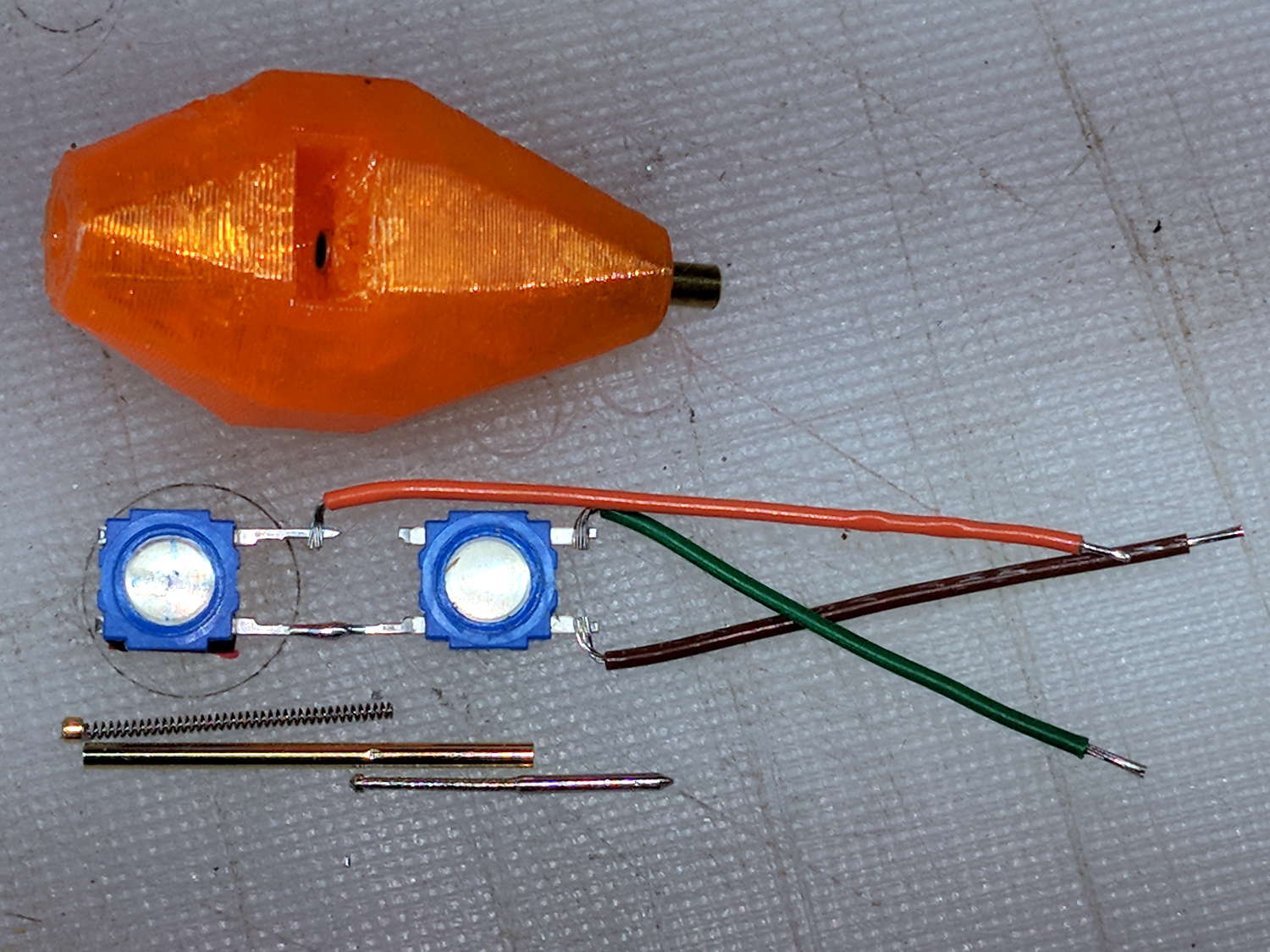
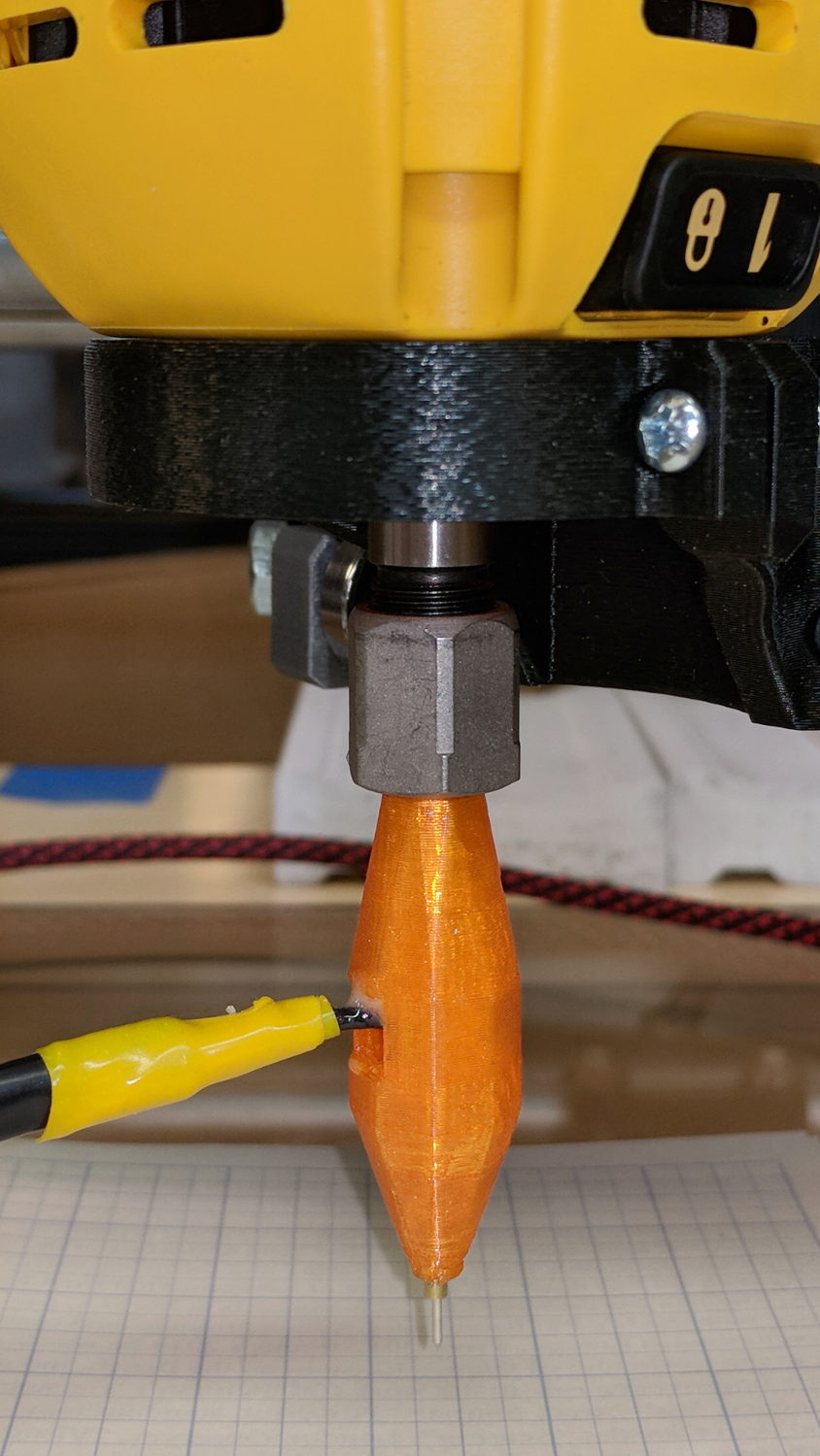
So I intended to shrink the Autolevel probe with 1/8 inch drill rod and a tactile membrane switch:
MPCNC – Simple Z probe – pogo tactile switch
Unfortunately, it didn’t work nearly as well as I expected, because the switch membrane requires slightly less than the 180 g of pressure that pushes the P100 pogo pin entirely into its housing, leaving no overtravel worth mentioning. The membrane switch mechanism itself has much less than 1 mm of overtravel after the dome snaps, which left me with an uncomfortable feeling of impending doom.
I managed to figure that out before completely assembling the thing, saving me a bit of time.
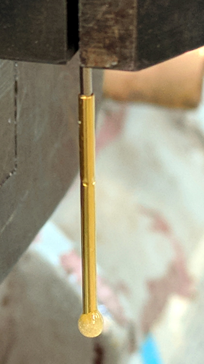
The end of the pogo pin initially sported a dot of epoxy to spread the load over the switch dome:
Pogo pin with epoxy switch-pusher drop
I dismantled the pogo pin to see whether I could substitute a more forceful spring how it worked. As expected, a teeny spring drives the probe up against a trio of indentations in the brass housing. I didn’t expect the probe to have such an intricate shape, but it’s obvious in retrospect.
The OpenSCAD code for the housing required minimal tweakage from the larger version, so it’s not worth immortalizing.
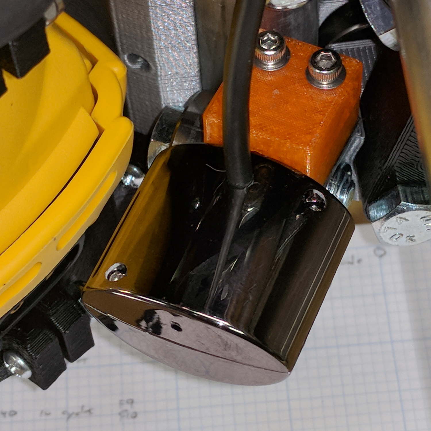
The bCNC doc shows a camera mount made from acrylic and aluminum, but the MPCNC tool carrier lacks anywhere to secure such a thing. The camera should be reasonably close to the spindle axis, high enough to clear the work, and stable enough to hold its alignment. There’s a tiny flat spot next to the outer-lower Z-axis bearing supports (along the bottom of the picture), so that’s where it must go:
MPCNC – Central Assembly – detail
At least for now, anyway.
The USB camera originally mounted on a spring clip, with a 10 mm ball at the end of a 6 mm OD × 6 mm long stalk. Because we live in the future, building a matching ball socket isn’t particularly difficult:
MPCNC – USB Camera mount – Slic3r
3D printing FTW!
The stalk opening slants downward by 5°, because the camera PCB isn’t quite aligned with the stalk and I couldn’t get the first version to aim the lens directly downward.
A pair of brass inserts anchor the two M3 SHCS. The clamping force seems barely adequate to the task, but I’ll wait to see what else I don’t like before complexicating the situation.
The MPCNC bearing bracket doesn’t provide much surface area for the foam and it’s a bit more flexy than I’d like, but good practice probably requires verifying the spindle-to-camera offset before trusting the results, so we’ll see how it works.
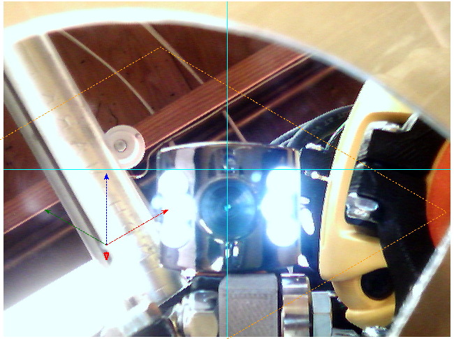
The initial camera alignment consists of putting a mirror flat on the (pretty much level) platform:
MPCNC USB Camera – mirror alignment
Then you adjust the camera so its lens looks squarely at itself in the middle of the image:
bCNC – Camera – Mirror Alignment – first mount
The picture shows the camera aligned left-to-right (because the ball can rotate around the shaft axis), but the first mount didn’t allow the stalk to have enough downward tilt to center the lens image on the horizontal crosshair, thus the -5° tilt appearing in the second version.
With the camera lens centered on its reflection, you know the optical axis is perpendicular to the mirror. Because the mirror is flat on the bench, the optical axis must be perpendicular to the bench, which is parallel to the XY plane. Because we assume the MPCNC Z-axis moves perpendicular to the bench = XY plane, the distance between the spindle axis and the camera axis will remain constant, regardless of the Z-axis position.
This file contains hidden or bidirectional Unicode text that may be interpreted or compiled differently than what appears below. To review, open the file in an editor that reveals hidden Unicode characters.
Learn more about bidirectional Unicode characters
Inside, it uses the same pushbutton and pogo pin as the pen holder design, with a similar brass tube around the pogo pin.
There’s a conspicuous lack of good wire management; we all know where those wires will snap. In practice, you’d secure it to the DW660 power cord, way up on top, to eliminate most of the flexing. Still, it wants better strain relief than its gets from those heatstink tubes.
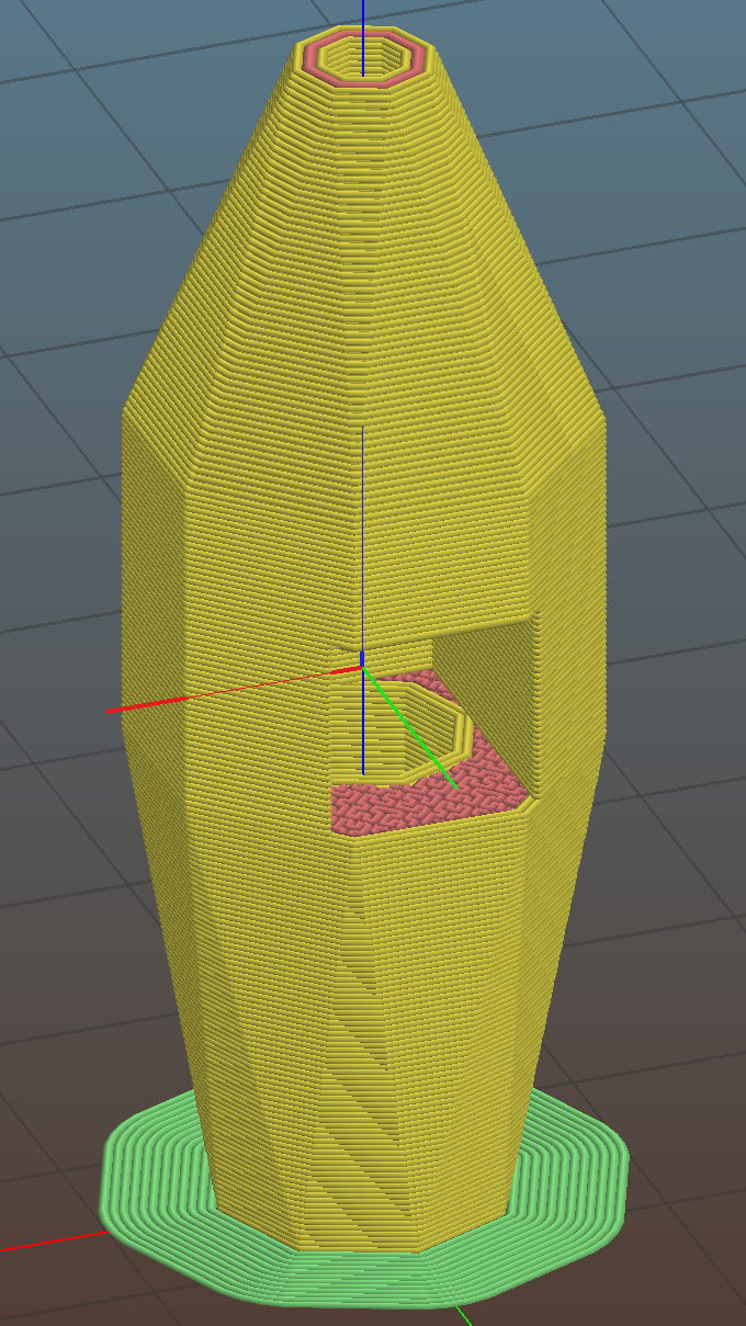
It’s sitting upside-down in a 5 mm brim for more platform adhesion.
The next one will have a 1/8 inch stud to fit the DW660’s other collet and shorten the top by 3/8 inch, because I want the rod inserted three diameters for stability. The bottom can’t get much shorter, because the pogo pin determines the switch-to-tip distance. Maybe a simple membrane switch will work well enough?
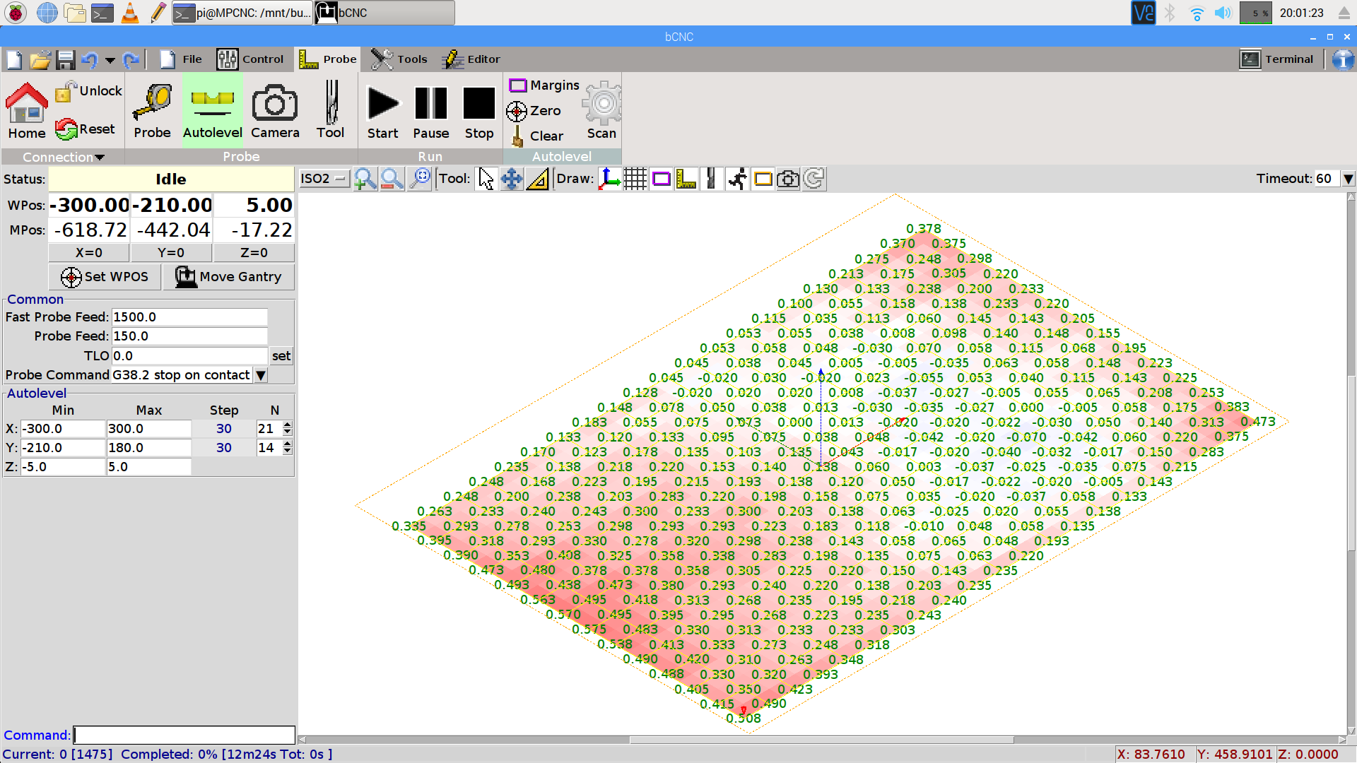
You can see the depression in the glass sheet pretty clearly in a bCNC Autolevel scan on 30 mm centers (clicky for more dots):
This file contains hidden or bidirectional Unicode text that may be interpreted or compiled differently than what appears below. To review, open the file in an editor that reveals hidden Unicode characters.
Learn more about bidirectional Unicode characters
The display started up fine, became encrypted during the next few hours, and remained garbled as the track information changed. This is almost certainly a bad SPI transfer trashing the OLED module’s control registers.
Dropping the clock to the absolute minimum of 0.5 MHz didn’t help, either:
serial = spi(device=0,port=0,bus_speed_hz=500000)
device = sh1106(serial)
This particular display woke up blank after loading the new code, then worked OK after another reset. The other streamers lit up as expected on the first try, so the slower SPI isn’t making the situation instantly worse.
Running the clock at 1 MHz definitely reduced the failure rate, which suggests it’s a glitchy thing.
Good embedded systems practice suggests resetting the entire display from scratch every now and again, but my streamer code has no concept of elapsed time. Opening that particular can o’ worms would almost certainly result in an on-screen clock and I do not want to go there.
I suppose I must get a new oscilloscope with SPI bus decoding to verify all the SPI setup and hold times …
After doing sudo modprobe uinput, lsmod | grep uinp returns nothing at all (Xubuntu 16.04), but evtest seems perfectly happy:
sudo evtest /dev/input/event17
Input driver version is 1.0.1
Input device ID: bus 0x3 vendor 0x58f product 0x9410 version 0x0
Input device name: "KB800 Kinesis Freestyle"
Supported events:
  Event type 0 (EV_SYN)
  Event type 1 (EV_KEY)
    Event code 113 (KEY_MUTE)
    Event code 114 (KEY_VOLUMEDOWN)
    Event code 115 (KEY_VOLUMEUP)
    Event code 140 (KEY_CALC)
Properties:
Testing ... (interrupt to exit)
Event: time 1518199358.454619, type 1 (EV_KEY), code 113 (KEY_MUTE), value 1
Event: time 1518199358.454619, -------------- SYN_REPORT ------------
Event: time 1518199358.454638, type 1 (EV_KEY), code 113 (KEY_MUTE), value 0
Event: time 1518199358.454638, -------------- SYN_REPORT ------------
Event: time 1518199361.014681, type 1 (EV_KEY), code 114 (KEY_VOLUMEDOWN), value 1
Event: time 1518199361.014681, -------------- SYN_REPORT ------------
Event: time 1518199361.014699, type 1 (EV_KEY), code 114 (KEY_VOLUMEDOWN), value 0
Event: time 1518199361.014699, -------------- SYN_REPORT ------------
Event: time 1518199361.654701, type 1 (EV_KEY), code 115 (KEY_VOLUMEUP), value 1
Event: time 1518199361.654701, -------------- SYN_REPORT ------------
Event: time 1518199361.654721, type 1 (EV_KEY), code 115 (KEY_VOLUMEUP), value 0
Event: time 1518199361.654721, -------------- SYN_REPORT ------------
Event: time 1518199362.294715, type 1 (EV_KEY), code 140 (KEY_CALC), value 1
Event: time 1518199362.294715, -------------- SYN_REPORT ------------
Event: time 1518199362.294733, type 1 (EV_KEY), code 140 (KEY_CALC), value 0
Event: time 1518199362.294733, -------------- SYN_REPORT ------------
And the keys work without any special configuration on my part. Apparently they’re already built into XFCE, despite the sound keys not showing up in the Keyboard Shortcuts control panel where you assign programs to keys.
This is wonderful work!
I’ve never seen so many calculators before! Oops.
There should be some udev-rule-ish way to automagically figure out which /dev/hidraw? device to use and symlink to a suitable alias, so the program could use it without knowing the actual device. A casual search turns up:
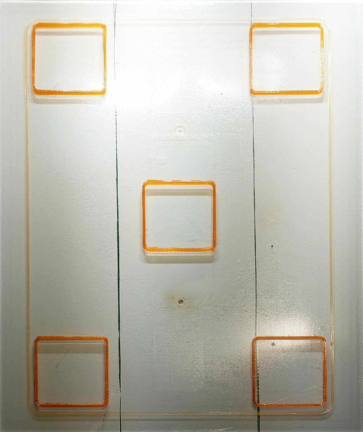
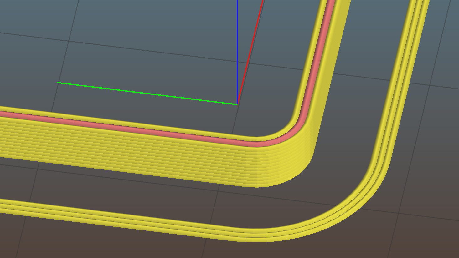
The skirt is scant at 0.20 mm, the boxes are 0.15 mm short at 2.85 mm, and the walls are 0.03 mm too thin. Some Z offset adjustment seems in order, as the first few layers (on the left) came out grossly squished:
Calibration box – 2.85 – detail
However, the box heights came out sufficiently uniform to show the platform alignment remains just fine.
Putting it there replaces all the mechanical putzing and adjusting cute little screws / bolts / nuts / spacers / suchlike with a simple offset in the startup G-Code:
G28 Z-2.15 ; home Z to platform switch, with measured offset
So I changed the startup G-Code in Slic3r to use G28 Z-2.30, sliced a single box in the middle of the platform, printed it, and … it came out exactly the same height: 2.85 mm.
Huh.
To make a very long story short, it turns out Marlin 1.1 ignores the numeric parameter in G28. When I updated the firmware to that version, I had changed the Configuration.h file to include the homing offsets:
So, with the same offset burned into the firmware, it looked like the startup G-Code was Doing The Right Thing. I never deleted the offset from the startup G-Code and, at some point, Marlin stopped supporting the numeric parameter.
Huh.
However, the X and Y homing offsets must be hardcoded, because I want the XY origin in the middle of the platform to match my original OpenSCAD part designs. Everybody else prefers the XY origin in the front-left corner. FWIW, in Marlin 1.1-RC5 (two years old by now), the #define BED_CENTER_AT_0_0 constant appears only in that line and nowhere else in the source code. Maybe it was a change in progress back then?
Anyhow, rather than hardcode the Z offset again, I set it to 0.00:
Recompile and reload the firmware, then change the startup G-Code to use G28 Z without the offset.
Doing so means I can measure and adjust the actual Z offset with M206, then store the value in EEPROM with M500:
M206 Z-2.25
M500
I went a little short at -2.25, for reasons I cannot explain now.
Measuring the offset goes like this:
Zero the offset: M206 Z0
Move the extruder off to the right: G0 X135
Home Z: G28 Z
Get some air under the nozzle: G0 Z4.0
Measure the actual clearance, perhaps using your taper gauge, at (let’s say) 1.7 mm
Set (1.7 – 4.0) as the offset: M206 Z-2.3
Print a box and adjust the offset accordingly
Using my actual measurement, not the for-instance example, I resliced the box, printed it, and it came out at 2.94 mm, just slightly short, so I re-tweaked the offset to Z-3.28 and re-stored it.
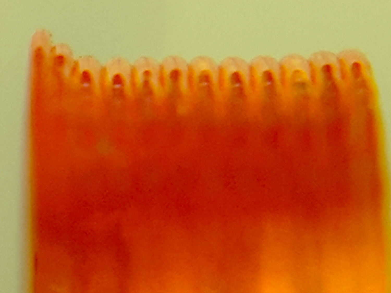
Embiggening the wall thickness turned out to be a matter of updating the filament diameter. I measured the start of the current spool of orange PETG at 1.75 mm, the same as the previous natural PETG spool, but the current section is 1.70 mm. Plugging that into Slic3r, reslicing, and reprinting produced a dead-on square: 3.00 mm tall with 1.20 mm walls:
Calibration Square series
The skirt now comes out at 0.25 mm, the way it should, too. The difference between the original 0.20 mm skirt and 0.25 mm suggests the squashed center thread (of the three in the skirt around the first set of five boxes) forced the two adjacent threads to become a bit taller, for lack of somewhere for the excess plastic to go on one side of each thread, and the nozzle rode higher than you’d (well, I’d) expect from the bare numbers.
The picture is missing a few squares in the middle, because I couldn’t believe changing the G28 Z-2.15 offset had no effect. It was easier to believe I’d inadvertently loaded the wrong file than the software / firmware was doing something wrong.
However, during the course of the adventure, I established M851 does exactly nothing in this context, perhaps because it applies to some different type of homing / probing / mesh leveling / whatever. You can set the Z offset with several other G-Code and M-Code commands, but the documentation isn’t always forthcoming about how the various methods interact and different firmware uses identical codes for completely different functions, so proceed with Exceedingly Great Caution.
In any event, it’s much easier and faster to adjust the printer & slicing parameters by measuring test boxes than by puzzling over actual prints, so …
This file contains hidden or bidirectional Unicode text that may be interpreted or compiled differently than what appears below. To review, open the file in an editor that reveals hidden Unicode characters.
Learn more about bidirectional Unicode characters
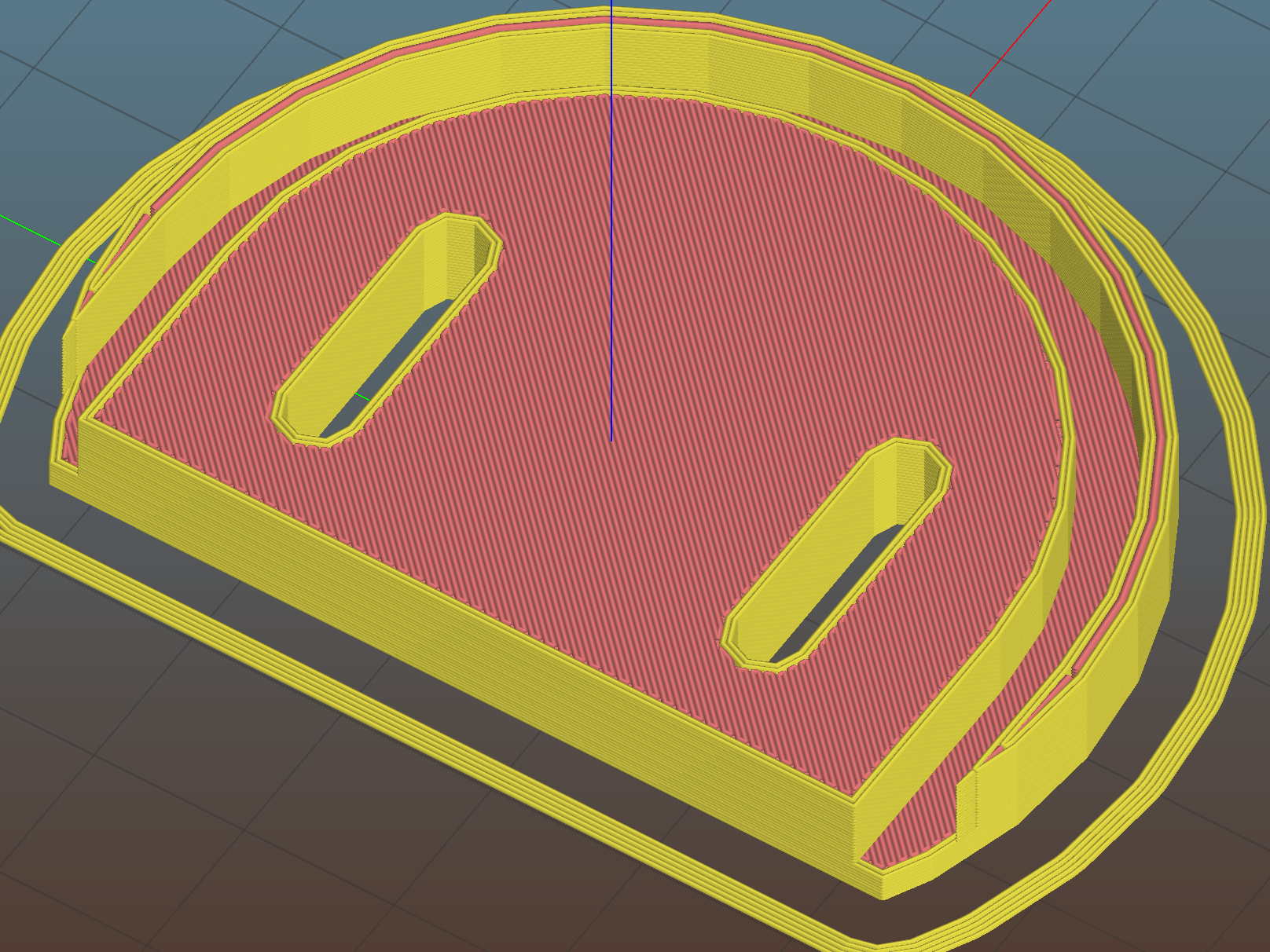
We just scrapped out the old dish drainer, only to find the gadget bin on the new drainer let the measuring spoons fall over and lie along its bottom. After a week of fishing them out from under paring knives, cheese slicers, and suchlike, I gimmicked up a holder:
Measuring Spoon Drainer – installed
One might suggest natural PETG, rather than orange, thereby displaying a shocking ignorance of the MVP concept. We’ll run with orange for the shakedown trials, then build-measure-learn, iterate, and, for all I know, we may even pivot.
A bottom-up view of the solid model shows the trench accommodating the bin lip:
This file contains hidden or bidirectional Unicode text that may be interpreted or compiled differently than what appears below. To review, open the file in an editor that reveals hidden Unicode characters.
Learn more about bidirectional Unicode characters