The Smell of Molten Projects in the Morning

Ed Nisley's Blog: Shop notes, electronics, firmware, machinery, 3D printing, laser cuttery, and curiosities. Contents: 100% human thinking, 0% AI slop.

Category: Software

General-purpose computers doing something specific

  • Mini-Lathe Ball Drilling Fixture

    Mini-Lathe Ball Drilling Fixture

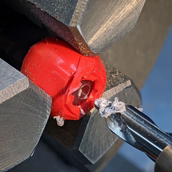
    Despite successfully drilling holes in a few plastic balls, I wanted a somewhat less terrifying setup than this:

    Micromark Ball Vise - lathe ball hack
    Micromark Ball Vise – lathe ball hack

    The stiffness of the bike helmet mirror mount suggested a similar clamp would have enough griptivity to immobilize the ball while cutting it in the lathe:

    Helmet Mirror Mount - 10 mm ball
    Helmet Mirror Mount – 10 mm ball

    Building the clamp around the lathe’s three-jaw lathe chuck eliminates the need for screws / washers / inserts:

    Lathe Ball Fixture - 19 mm - Show
    Lathe Ball Fixture – 19 mm – Show

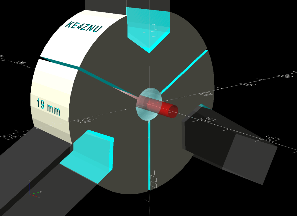
    The Ah-ha! moment came when I realized the fixture can expose half of the ball’s diameter for drilling while clamping 87% of its diameter, because 0.5 = sin 30° and 0.87 = cos 30°:

    Lathe Ball Fixture - 19 mm - Show - front orthogonal
    Lathe Ball Fixture – 19 mm – Show – front orthogonal

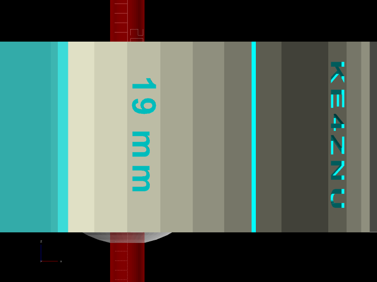
    That’s an orthogonal view showing 13% of the ball radius sticking out of the fixture; it’s 6% of the diameter.

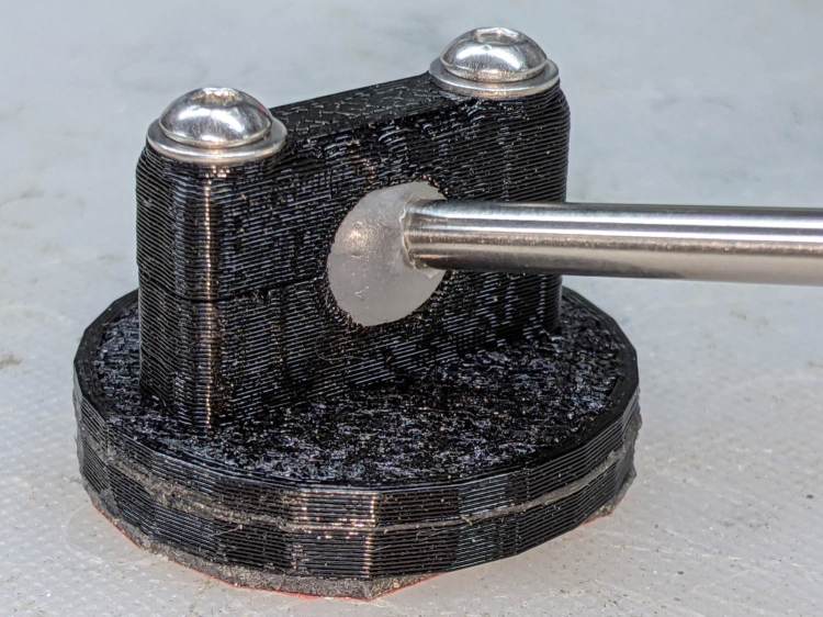
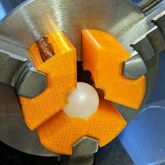
    Which looks like this in real life:

    Lathe Ball Fixture - 19 mm - sections with ball
    Lathe Ball Fixture – 19 mm – sections with ball

    The socket is offset toward the tailstock end of the clamp (on the right in the picture) to expose half its diameter flush with the surface perpendicular to the lathe axis. The other side necks down into a cylinder of the same diameter to clear the drill bit.

    This works nicely until the ball diameter equals the chuck jaw’s 20 mm length, whereupon larger balls protrude into the chuck body’s spindle opening. Although I haven’t yet built one, the 25 mm balls in my Box o’ Bearings should fit, with exceedingly sissy cuts required for large holes.

    The fixture doesn’t require support material, because the axial holes eliminate the worst of the overhang. Putting the tailstock side flat on the platform gives it the best-looking surface:

    Lathe Ball Fixture - 19 mm - Slic3r - equator
    Lathe Ball Fixture – 19 mm – Slic3r – equator

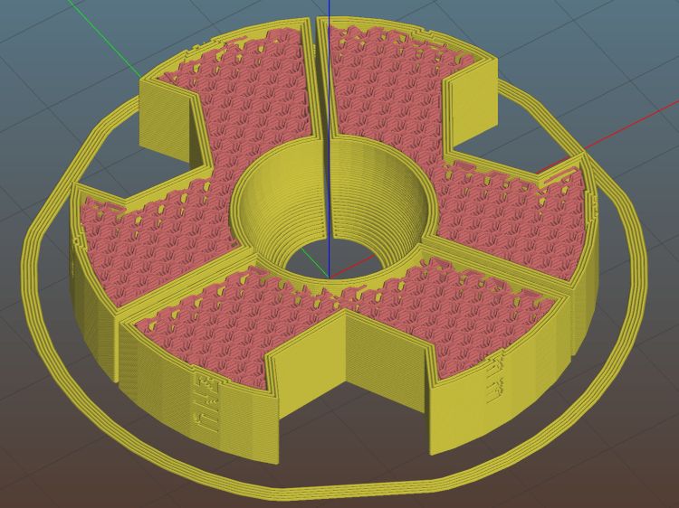
    The kerf between the segments ensures the jaws can apply pressure to the ball, whereupon the usual crappy serrated 3D printed surface firmly grabs it.

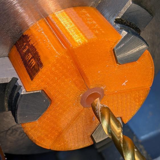
    The fixture is a slip fit on the chuck jaws:

    Lathe Ball Fixture - 19 mm - installed
    Lathe Ball Fixture – 19 mm – installed

    Tightening the jaws shoves them all the way into the fixture’s slots and clamps the ball:

    Lathe Ball Fixture - 19 mm - center drill
    Lathe Ball Fixture – 19 mm – center drill

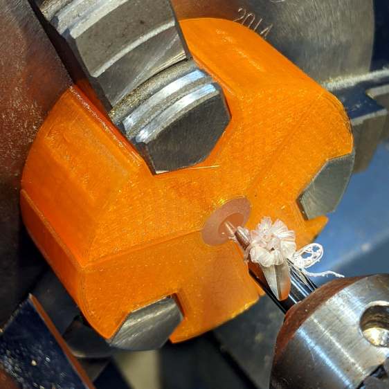
    Overtightening the chuck will (probably) compress the ball around the drill, which will (best case) give you slightly oversize holes or (worst case) cause the ball to seize / melt around the drill bit, so sleaze up to the correct hole diameter maybe half a millimeter at a time:

    Lathe Ball Fixture - 19 mm - 6 mm drill
    Lathe Ball Fixture – 19 mm – 6 mm drill

    That fixture exposes 9.5 mm = 19/2 of the ball. The drill makes a 6 mm hole to fit the telescoping shaft seen above.

    Obviously, you must build a custom fixture for every ball diameter in your inventory, which is no big deal when you have a hands-off manufacturing process. Embossing the diameter into the fixture helps match them, although the scribbled Sharpie isn’t particularly elegant.

    The OpenSCAD source code as a GitHub Gist:

    // Lathe Ball Drilling Fixture
    // Ed Nisley KE4ZNU 2020-11
    /* [Layout options] */
    Layout = "Build"; // [Build, Show, Body, Jaws]
    BallDia = 10.0; // [5.0:0.5:25.0]
    /* [Extrusion parameters] */
    /* [Hidden] */
    ThreadThick = 0.25;
    ThreadWidth = 0.40;
    HoleWindage = 0.2;
    function IntegerMultiple(Size,Unit) = Unit * ceil(Size / Unit);
    function IntegerLessMultiple(Size,Unit) = Unit * floor(Size / Unit);
    Protrusion = 0.1; // make holes end cleanly
    inch = 25.4;
    ID = 0;
    OD = 1;
    LENGTH = 2;
    //* [Basic dimensions] */
    Chuck = [21.0,100.0,20.0]; // chuck bore, OD, jaw length
    Jaw = [Chuck[LENGTH],15.0,12.0]; // jaw free length, base width, first step radius
    JawInclAngle = 112; // < 120 degrees for clearance!
    JawAngle = JawInclAngle/2; // angle from radius
    WallThick = 5.0; // min wall thickness
    Kerf = 0.75; // space between clamp blocks
    ClampSides = 8*(2*3);
    ClampBore = BallDia/2; // clear bore through clamp
    ClampAngle = asin(ClampBore/BallDia); // angle from lathe axis to clamp front
    Plate = [ClampBore,
    BallDia + 2*WallThick + 2*Jaw.z,
    Jaw.x];
    LegendDepth = 1*ThreadWidth;
    ShaftOD = 3.6; // sample shaft
    ShowGap = 1.5;
    //———————-
    // Chuck jaws
    // Real jaws have a concave radiused tip we simply ignore
    module ChuckJaws(l=Jaw.x,r=10) {
    for (a=[0:120:240])
    rotate(a)
    linear_extrude(height=l)
    translate([r,0])
    difference() {
    translate([Chuck[OD]/4,0])
    square([Chuck[OD]/2,Jaw.y],center=true);
    for (i=[-1,1])
    rotate(i*(90 – JawAngle))
    translate([-Jaw.z/2,0])
    square([Jaw.z,2*Jaw.y],center=true);
    }
    }
    //———————-
    // Clamp body
    module ClampBlocks() {
    difference() {
    cylinder(d=Plate[OD],h=Plate[LENGTH],$fn=ClampSides); // main disk
    translate([0,0,-Protrusion]) // central bore
    cylinder(d=ClampBore,h=2*Plate[LENGTH],$fn=ClampSides);
    for (a=[0:120:240]) // kerf slits
    rotate(60 + a)
    translate([Plate[OD]/2,0,Protrusion])
    cube([Plate[OD],Kerf,2*Plate[LENGTH]],center=true);
    translate([0,0,BallDia/2 * cos(ClampAngle)]) // ball socket
    sphere(d=BallDia,$fn=ClampSides);
    for (a=[0:120:240]) { // legend
    rotate(4.5*360/ClampSides + a)
    translate([Plate[OD]/2 – LegendDepth,0,Plate[LENGTH]/2])
    rotate([0,90,0])
    linear_extrude(height=LegendDepth + Protrusion,convexity=10)
    mirror([0,0,0])
    text(text=str(BallDia," mm"),size=2.5,spacing=1.20,font="Arial:style:Bold",halign="center",valign="center");
    rotate(-4.5*360/ClampSides + a)
    translate([Plate[OD]/2 – LegendDepth,0,Plate[LENGTH]/2])
    rotate([0,90,0])
    linear_extrude(height=LegendDepth + Protrusion,convexity=10)
    mirror([0,0,0])
    text(text="KE4ZNU",size=2.5,spacing=1.20,font="Arial:style:Bold",halign="center",valign="center");
    }
    }
    }
    //———————-
    // Clamp with jaw cutouts
    module ClampBody() {
    difference() {
    ClampBlocks();
    translate([0,0,-Protrusion])
    ChuckJaws(l=Jaw.x + 2*Protrusion,r=BallDia/2 + WallThick);
    }
    }
    //———————-
    // Lash it together
    if (Layout == "Body") {
    ClampBlocks();
    }
    if (Layout == "Jaws") {
    ChuckJaws();
    }
    if (Layout == "Build") {
    ClampBody();
    }
    if (Layout == "Show") {
    ClampBody();
    color("ivory",0.2)
    ChuckJaws(r=BallDia/2 + WallThick + ShowGap); // move out for E-Z viewing
    color("red",0.4)
    translate([0,0,-Jaw.x/2])
    cylinder(d=ShaftOD,h=2*Jaw.x,$fn=ClampSides,center=false);
    color("white",0.5)
    translate([0,0,BallDia/2 * cos(ClampAngle)]) // ball socket
    sphere(d=BallDia,$fn=ClampSides);
    }

    The dimension doodles, including some notions that didn’t work:

    Lathe Ball Clamp - dimension doodles
    Lathe Ball Clamp – dimension doodles
  • Arducam Motorized Focus Camera: Rotary Encoder and Equation

    Arducam Motorized Focus Camera: Rotary Encoder and Equation

    Mashing rotary encoder reading together with the focus-distance-to-DAC equation produces well-behaved camera focusing.

    First, set up another test range:

    Arducam Motorized Focus Camera - desktop test range
    Arducam Motorized Focus Camera – desktop test range

    Run the test code:

    # Simpleminded focusing test for
    #  Arducam Motorized Focus Camera
    # Gets events through evdev from rotary encoder knob
    
    # Ed Nisley - KE4ZNU
    # 2020-10-20
    
    import sys
    import math
    import evdev
    import smbus
    
    # useful functions
    
    def DAC_from_distance(dist):
        return math.trunc(256*(10.8 + 2180/dist))
    
    # write DAC word to camera I2C bus device
    #  and ignore the omnipresent error return
    
    def write_lens_DAC(bus,addr,val):
        done = False
        while not done:
            try:
                bus.write_word_data(addr,val >> 8,val & 0xff)
            except OSError as e:
                if e.errno == 121:
    #                print('OS remote error ignored')
                    done = True
            except:
                print(sys.exc_info()[0],sys.exc_info()[1])
            else:
                print('Write with no error!')
                done = True
    
    # set up focus distances
    
    closest = 50            # mm
    farthest = 500
    nominal = 100           # default focus distance
    
    foci = [n for n in range(closest,nominal,5)] \
         + [n for n in range(nominal,250,10)]  \
         + [n for n in range(250,1501,25)]
    
    # compute DAC equivalents for each distance
    
    foci_DAC = list(map(DAC_from_distance,foci))
    
    focus_index = foci.index(nominal)
    
    # set up the I2C bus
    
    f = smbus.SMBus(0)
    lens = 0x0c
    
    # set up the encoder device handler
    # requires rotary-encoder dtoverlay aimed at pins 20 & 21
    
    d = evdev.InputDevice('/dev/input/by-path/platform-rotary@14-event')
    print('Rotary encoder device: {}'.format(d.name))
    
    # set initial focus
    
    write_lens_DAC(f,lens,foci_DAC[focus_index])
    
    # fetch I2C events and update the focus forever
    
    for e in d.read_loop():
    #    print('Event: {}'.format(e))
    
        if e.type == evdev.ecodes.EV_REL:
    #        print('Rel: {}'.format(e.value))
    
            if (e.value > 0 and focus_index < len(foci) - 1) or (e.value < 0 and focus_index > 0):
                focus_index += e.value
    
            dist = foci[focus_index]
            dac = foci_DAC[focus_index]
    
            print('Distance: {:4d} mm DAC: {:5d} {:04x} i: {:3d}'.format(dist,dac,dac,focus_index))
    
            write_lens_DAC(f,lens,dac)
    

    Because the knob produces increments of ±1, the code accumulates them into an index for the foci & foci_DAC lists, then sends the corresponding entry from the latter to the lens on every rotary encoder event.

    And then It Just Works!

    The camera powers up with the lens focused at infinity (or slightly beyond), but setting it to 100 mm seems more useful:

    Arducam Motorized Focus Camera - 100 mm
    Arducam Motorized Focus Camera – 100 mm

    Turning the knob counterclockwise runs the focus inward to 50 mm:

    Arducam Motorized Focus Camera - 50 mm
    Arducam Motorized Focus Camera – 50 mm

    Turning it clockwise cranks it outward to 1500 mm:

    Arducam Motorized Focus Camera - 1500 mm
    Arducam Motorized Focus Camera – 1500 mm

    The mug is about 300 mm away, so the depth of field extends from there to infinity (and beyond).

    It needs more work, but now it has excellent upside potential!

  • Raspberry Pi Rotary Encoder: Knob Switch Key

    Raspberry Pi Rotary Encoder: Knob Switch Key

    The rotary encoder knob I’m using for these tests has a pushbutton switch in its shaft:

    RPi rotary encoder - improved test fixture
    RPi rotary encoder – improved test fixture

    Now that I know where to look, it turns out there’s a Raspberry Pi overlay for that:

    Name:   gpio-key
    Info:   This is a generic overlay for activating GPIO keypresses using
            the gpio-keys library and this dtoverlay. Multiple keys can be
            set up using multiple calls to the overlay for configuring
            additional buttons or joysticks. You can see available keycodes
            at https://github.com/torvalds/linux/blob/v4.12/include/uapi/
            linux/input-event-codes.h#L64
    Load:   dtoverlay=gpio-key,<param>=<val>
    Params: gpio                    GPIO pin to trigger on (default 3)
            active_low              When this is 1 (active low), a falling
                                    edge generates a key down event and a
                                    rising edge generates a key up event.
                                    When this is 0 (active high), this is
                                    reversed. The default is 1 (active low)
            gpio_pull               Desired pull-up/down state (off, down, up)
                                    Default is "up". Note that the default pin
                                    (GPIO3) has an external pullup
            label                   Set a label for the key
            keycode                 Set the key code for the button


    Snuggle the button configuration next to the encoder in /boot/config.txt:

    dtoverlay=rotary-encoder,pin_a=20,pin_b=21,relative_axis=1,steps-per-period=2<br>dtoverlay=gpio-key,gpio=26,keycode=83,label="KNOB"
    

    I haven’t yet discovered where the label text appears, because I picked a keycode defining the button as the decimal point key on a numeric keypad. Perhaps one could create a unique key from whole cloth, but that’s in the nature of fine tuning. In any event, pressing / releasing the button produces key-down / key-up events just like you’d get from a real keyboard.

    The four pins required for the encoder + switch make a tidy block at the right (in this view, left as shown above) end of the RPi’s header:

    Raspberry Pi pinout
    Raspberry Pi pinout

    If you needed the SPI1 hardware, you’d pick different pins.

    Reboot that sucker and another input device appears:

    ll /dev/input/by-path/
    total 0
    lrwxrwxrwx 1 root root 9 Oct 18 10:00 platform-button@1a-event -> ../event0
    lrwxrwxrwx 1 root root 9 Oct 18 10:00 platform-rotary@14-event -> ../event2
    lrwxrwxrwx 1 root root 9 Oct 18 10:00 platform-soc:shutdown_button-event -> ../event1

    As with the encoder device, the button device name includes the hex equivalent of the pin number: 26 decimal = 0x1a.

    Run some code:

    # Keypress from Raspberry Pi GPIO pin using evdev
    # Add to /boot/config.txt
    #  dtoverlay=gpio-key,gpio=26,keycode=83,label="KNOB"
    
    import evdev
    
    b = evdev.InputDevice('/dev/input/by-path/platform-button@1a-event')
    print('Button device: {}'.format(b.name))
    
    print(' caps: {}'.format(b.capabilities(verbose=True)))
    print(' fd: {}'.format(b.fd))
    
    for e in b.read_loop():
        print('Event: {}'.format(e))
        if e.type == evdev.ecodes.EV_KEY:
            print('Key {}: {}'.format(e.code,e.value))


    Which produces this output:

    Button device: button@1a
    caps: {('EV_SYN', 0): [('SYN_REPORT', 0), ('SYN_CONFIG', 1)], ('EV_KEY', 1): [('KEY_KPDOT', 83)]}
    fd: 3
    Event: event at 1603036309.683348, code 83, type 01, val 01
    Key 83: 1
    Event: event at 1603036309.683348, code 00, type 00, val 00
    Event: event at 1603036310.003329, code 83, type 01, val 00
    Key 83: 0
    Event: event at 1603036310.003329, code 00, type 00, val 00

    All in all, that was easy …

  • Raspberry Pi Rotary Encoder: evdev Proof of Concept

    Raspberry Pi Rotary Encoder: evdev Proof of Concept

    After Bill Wittig pointed me in the right direction, writing a Python program to correctly read a rotary encoder knob on a Raspberry Pi is straightforward. At least given some hints revealed by knowing the proper keywords.

    First, enhance the knob’s survivability & usability by sticking it on a perfboard scrap:

    RPi rotary encoder - improved test fixture
    RPi rotary encoder – improved test fixture

    Then find the doc in /boot/overlays/README:

    Name: rotary-encoder
    Info: Overlay for GPIO connected rotary encoder.
    Load: dtoverlay=rotary-encoder,
    =
    Params: pin_a GPIO connected to rotary encoder channel A
    (default 4).
    pin_b GPIO connected to rotary encoder channel B
    (default 17).
    relative_axis register a relative axis rather than an
    absolute one. Relative axis will only
    generate +1/-1 events on the input device,
    hence no steps need to be passed.
    linux_axis the input subsystem axis to map to this
    rotary encoder. Defaults to 0 (ABS_X / REL_X)
    rollover Automatic rollover when the rotary value
    becomes greater than the specified steps or
    smaller than 0. For absolute axis only.
    steps-per-period Number of steps (stable states) per period.
    The values have the following meaning:
    1: Full-period mode (default)
    2: Half-period mode
    4: Quarter-period mode
    steps Number of steps in a full turnaround of the
    encoder. Only relevant for absolute axis.
    Defaults to 24 which is a typical value for
    such devices.
    wakeup Boolean, rotary encoder can wake up the
    system.
    encoding String, the method used to encode steps.
    Supported are "gray" (the default and more
    common) and "binary".

    Add a line to /boot/config.txt to configure the hardware:

    dtoverlay=rotary-encoder,pin_a=20,pin_b=21,relative_axis=1,steps-per-period=2

    The overlay enables the pullup resistors by default, so the encoder just pulls the pins to common. Swapping the pins reverses the sign of the increments, which may be easier than swapping the connector after you have it all wired up.

    The steps-per-period matches the encoder in hand, which has 30 detents per full turn; the default value of 1 step/period resulted in every other detent doing nothing. A relative axis produces increments of +1 and -1, rather than the accumulated value useful for an absolute encoder with hard physical stops.

    Reboot that sucker and an event device pops up:

    ll /dev/input
    total 0
    drwxr-xr-x 2 root root 80 Oct 18 07:46 by-path
    crw-rw---- 1 root input 13, 64 Oct 18 07:46 event0
    crw-rw---- 1 root input 13, 65 Oct 18 07:46 event1
    crw-rw---- 1 root input 13, 63 Oct 18 07:46 mice

    I’m unable to find the udev rule (or whatever) creating those aliases and, as with all udev trickery, the device’s numeric suffix is not deterministic. The only way you (well, I) can tell which device is the encoder and which is the power-off button is through their aliases:

    ll /dev/input/by-path/
    total 0
    lrwxrwxrwx 1 root root 9 Oct 18 07:46 platform-rotary@14-event -> ../event0
    lrwxrwxrwx 1 root root 9 Oct 18 07:46 platform-soc:shutdown_button-event -> ../event1

    The X axis of the mice device might report the same values, but calling a rotary encoder a mouse seems fraught with technical debt.

    The name uses the hex equivalent of the A channel pin number (20 = 0x14), so swapping the pins in the configuration will change the device name; rewiring the connector may be easier.

    Using the alias means you always get the correct device:

    # Rotary encoder using evdev
    # Add to /boot/config.txt
    #  dtoverlay=rotary-encoder,pin_a=20,pin_b=21,relative_axis=1,steps-per-period=2
    # Tweak pins and steps to match the encoder
    
    import evdev
    
    d = evdev.InputDevice('/dev/input/by-path/platform-rotary@14-event')
    print('Rotary encoder device: {}'.format(d.name))
    
    position = 0
    
    for e in d.read_loop():
        print('Event: {}'.format(e))
        if e.type == evdev.ecodes.EV_REL:
            position += e.value
            print('Position: {}'.format(position))
    

    Which should produce output along these lines:

    Rotary encoder device: rotary@14
    Event: event at 1603019654.750255, code 00, type 02, val 01
    Position: 1
    Event: event at 1603019654.750255, code 00, type 00, val 00
    Event: event at 1603019654.806492, code 00, type 02, val 01
    Position: 2
    Event: event at 1603019654.806492, code 00, type 00, val 00
    Event: event at 1603019654.949199, code 00, type 02, val 01
    Position: 3
    Event: event at 1603019654.949199, code 00, type 00, val 00
    Event: event at 1603019655.423506, code 00, type 02, val -1
    Position: 2
    Event: event at 1603019655.423506, code 00, type 00, val 00
    Event: event at 1603019655.493140, code 00, type 02, val -1
    Position: 1
    Event: event at 1603019655.493140, code 00, type 00, val 00
    Event: event at 1603019655.624685, code 00, type 02, val -1
    Position: 0
    Event: event at 1603019655.624685, code 00, type 00, val 00
    Event: event at 1603019657.652883, code 00, type 02, val -1
    Position: -1
    Event: event at 1603019657.652883, code 00, type 00, val 00
    Event: event at 1603019657.718956, code 00, type 02, val -1
    Position: -2
    Event: event at 1603019657.718956, code 00, type 00, val 00
    Event: event at 1603019657.880569, code 00, type 02, val -1
    Position: -3
    Event: event at 1603019657.880569, code 00, type 00, val 00
    

    The type 00 events are synchronization points, which might be more useful with more complex devices.

    Because the events happen outside the kernel scheduler’s notice, you (well, I) can now spin the knob as fast as possible and the machinery will generate one increment per transition, so the accumulated position changes smoothly.

    Much better!

  • Raspberry Pi Interrupts vs. Rotary Encoder

    Raspberry Pi Interrupts vs. Rotary Encoder

    Thinking about using a rotary encoder to focus a Raspberry Pi lens led to a testbed:

    RPi knob encoder test setup
    RPi knob encoder test setup

    There’s not much to it, because the RPi can enable pullup resistors on its digital inputs, whereupon the encoder switches its code bits to common. The third oscilloscope probe to the rear syncs on a trigger output from my knob driver.

    I started with the Encoder library from PyPi, but the setup code doesn’t enable the pullup resistors and the interrupt (well, it’s a callback) handler discards the previous encoder state before using it, so the thing can’t work. I kept the overall structure, gutted the code, and rebuilt it around a state table. The code appears at the bottom, but you won’t need it.

    Here’s the problem, all in one image:

    Knob Encoder - ABT - fast - overview
    Knob Encoder – ABT – fast – overview

    The top two traces are the A and B encoder bits. The bottom trace is the trigger output from the interrupt handler, which goes high at the start of the handler and low at the end, with a negative blip in the middle when it detects a “no motion” situation: the encoder output hasn’t changed from the last time it was invoked.

    Over on the left, where the knob is turning relatively slowly, the first two edges have an interrupt apiece. A detailed view shows them in action (the bottom half enlarge the non-shaded part of the top half):

    Knob Encoder - ABT - fast - first IRQs
    Knob Encoder – ABT – fast – first IRQs

    Notice that each interrupt occurs about 5 ms after the edge causing it!

    When the edges occur less than 5 ms apart, the driver can’t keep up. The next four edges produce only three interrupts:

    Knob Encoder - ABT - fast - 4 edges 3 IRQ
    Knob Encoder – ABT – fast – 4 edges 3 IRQ

    A closer look at the three interrupts shows all of them produced the “no motion” pulse, because they all sampled the same (incorrect) input bits:

    Knob Encoder - ABT - fast - 4 edges 3 IRQ - detail
    Knob Encoder – ABT – fast – 4 edges 3 IRQ – detail

    In fact, no matter how many edges occur, you only get three interrupts:

    Knob Encoder - ABT - fast - 9 edges 3 IRQ
    Knob Encoder – ABT – fast – 9 edges 3 IRQ

    The groups of interrupts never occur less than 5 ms apart, no matter how many edges they’ve missed. Casual searching suggests the Linux Completely Fair Scheduler has a minimum timeslice / thread runtime around 5 ms, so the encoder may be running at the fastest possible response for a non-real-time Raspberry Pi kernel, at least with a Python handler.

    If. I. Turn. The. Knob. Slowly. Then. It. Works. Fine. But. That. Is. Not. Practical. For. My. Purposes.

    Nor anybody else’s purposes, really, which leads me to think very few people have ever tried lashing a rotary encoder to a Raspberry Pi.

    So, OK, I’ll go with Nearer and Farther focusing buttons.

    The same casual searching suggested tweaking the Python thread’s priority / niceness could lock it to a different CPU core and, obviously, writing the knob handler in C / C++ / any other language would improve the situation, but IMO the result doesn’t justify the effort.

    It’s worth noting that writing “portable code” involves more than just getting it to run on a different system with different hardware. Rotary encoder handlers are trivial on an Arduino or, as in this case, even an ARM-based Teensy, but “the same logic” doesn’t deliver the same results on an RPi.

    My attempt at a Python encoder driver + simple test program as a GitHub Gist:

    # Rotary encoder test driver
    # Ed Nisley – KE4ZNU
    # Adapted from https://github.com/mivallion/Encoder
    # State table from https://github.com/PaulStoffregen/Encoder
    import RPi.GPIO as GPIO
    class Encoder(object):
    def __init__(self, A, B, T=None, Delay=None):
    GPIO.setmode(GPIO.BCM)
    self.T = T
    if T is not None:
    GPIO.setup(T, GPIO.OUT)
    GPIO.output(T,0)
    GPIO.setup(A, GPIO.IN, pull_up_down=GPIO.PUD_UP)
    GPIO.setup(B, GPIO.IN, pull_up_down=GPIO.PUD_UP)
    self.delay = Delay
    self.A = A
    self.B = B
    self.pos = 0
    self.state = (GPIO.input(B) << 1) | GPIO.input(A)
    self.edges = (0,1,-1,2,-1,0,-2,1,1,-2,0,-1,2,-1,1,0)
    if self.delay is not None:
    GPIO.add_event_detect(A, GPIO.BOTH, callback=self.__update,
    bouncetime=self.delay)
    GPIO.add_event_detect(B, GPIO.BOTH, callback=self.__update,
    bouncetime=self.delay)
    else:
    GPIO.add_event_detect(A, GPIO.BOTH, callback=self.__update)
    GPIO.add_event_detect(B, GPIO.BOTH, callback=self.__update)
    def __update(self, channel):
    if self.T is not None:
    GPIO.output(self.T,1) # flag entry
    state = (self.state & 0b0011) \
    | (GPIO.input(self.B) << 3) \
    | (GPIO.input(self.A) << 2)
    gflag = '' if self.edges[state] else ' – glitch'
    if (self.T is not None) and not self.edges[state]: # flag no-motion glitch
    GPIO.output(self.T,0)
    GPIO.output(self.T,1)
    self.pos += self.edges[state]
    self.state = state >> 2
    # print(' {} – state: {:04b} pos: {}{}'.format(channel,state,self.pos,gflag))
    if self.T is not None:
    GPIO.output(self.T,0) # flag exit
    def read(self):
    return self.pos
    def read_reset(self):
    rv = self.pos
    self.pos = 0
    return rv
    def write(self,pos):
    self.pos = pos
    if __name__ == "__main__":
    import encoder
    import time
    from gpiozero import Button
    btn = Button(26)
    enc = encoder.Encoder(20, 21,T=16)
    prev = enc.read()
    while not btn.is_held :
    now = enc.read()
    if now != prev:
    print('{:+4d}'.format(now))
    prev = now
    view raw encoder.py hosted with ❤ by GitHub

  • Kenmore Progressive Vacuum Cleaner vs. Dust Brush Adapters

    Kenmore Progressive Vacuum Cleaner vs. Dust Brush Adapters

    Contemporary vacuum cleaner dust brush heads have bristles in some combination of [long | short] with [flexy | stiff]. The long + flexy combination results in the bristles jamming the inlet and the short + stiff combo seems unsuited for complex surfaces. Shaking the Amazonian dice brought a different combination:

    Vacuum cleaner dust brush assortment - with adapters
    Vacuum cleaner dust brush assortment – with adapters

    That’s the new one on the bottom and, contrary to what you might think from the picture, it is not identical to the one just above it.

    In particular, the black plastic housing came from a different mold (the seam lines are now top-and-bottom) and required a new adapter for the Kenmore Progressive vacuum cleaner’s complicated wand / hose inlet, with a 3/4 inch PVC pipe reinforcement inside.

    Early reports indicate it works fine, so I’ll declare a temporary victory in the war on entropy.

    I’m still using the same OpenSCAD source code with minute tweaks to suit the as-measured tapers.

  • Monthly Science: Burnett Signal Timing

    Monthly Science: Burnett Signal Timing

    The NYS DOT has been improving the pedestrian crossings at the Burnett – Rt 55 intersection. I expect this will be a bullet item in their Complete Streets compliance document, with favorable job reviews for all parties. The situation for bicyclists using the intersection, which provides the only access from Poughkeepsie to the Dutchess Rail Trail, hasn’t changed in the slightest. No signal timing adjustments, no bike-capable sensor loops, no lane markings, no shoulders, no nothing.

    Here’s what NYS DOT’s Complete Streets program looks like from our perspective, with the four-digit frame numbers ticking along at 60 frame/sec.

    We’re waiting on Overocker Rd for Burnett traffic to clear enough to cross three lanes from a cold start:

    Burnett Signal - 2020-09-25 - front 0006
    Burnett Signal – 2020-09-25 – front 0006

    That building over there across Burnett is the NYS DOT Region 8 Headquarters, so we’re not in the hinterlands where nobody ever goes.

    We’re rolling:

    Burnett Signal - 2020-09-25 - front 0258
    Burnett Signal – 2020-09-25 – front 0258

    The Burnett signals just turned green, although the cars haven’t started moving yet, and we’re accelerating out of Overocker:

    Burnett Signal - 2020-09-25 - front 0463
    Burnett Signal – 2020-09-25 – front 0463

    About 1.5 seconds later, the vehicles have started moving and we’re lining up for the left side of the right-hand lane:

    Burnett Signal - 2020-09-25 - front 0752
    Burnett Signal – 2020-09-25 – front 0752

    There’s no traffic behind us, so we can ride a little more to the right than we usually do, in the hopes of triggering the signal’s unmarked sensor loop:

    Burnett Signal - 2020-09-25 - front 1178
    Burnett Signal – 2020-09-25 – front 1178

    We didn’t expect anything different:

    Burnett Signal - 2020-09-25 - front 1333
    Burnett Signal – 2020-09-25 – front 1333

    We’re rolling at about 12 mph and it’s unreasonable to expect us to jam to a stop whenever the signal turns yellow. Oh, did you notice the truck parked in the sidewalk over on the left?

    As usual, 4.3 seconds later, the Burnett signals turn red, so we’re now riding in the “intersection clearing” delay:

    Burnett Signal - 2020-09-25 - front 1593
    Burnett Signal – 2020-09-25 – front 1593

    Two seconds later, the Rt 55 signals turn green:

    Burnett Signal - 2020-09-25 - front 1711
    Burnett Signal – 2020-09-25 – front 1711

    Did you notice all three eastbound lanes of Rt 55 (on our right) were occupied? That means a driver can’t come zipping through without stopping at the green light in their direction.

    One second later, we’re still proceeding through the intersection, clearing the lethally smooth manhole cover by a few inches, and approaching the far side:

    Burnett Signal - 2020-09-25 - front 1771
    Burnett Signal – 2020-09-25 – front 1771

    Here’s what the intersection looks like behind me:

    Burnett Signal - 2020-09-25 - rear 1
    Burnett Signal – 2020-09-25 – rear 1

    Another second goes by and we’re pretty much into the far right lane , with the westbound traffic beginning to move:

    Burnett Signal - 2020-09-25 - front 1831
    Burnett Signal – 2020-09-25 – front 1831

    The pedestrian crossing ladder has fresh new paint. They milled off the old paint while reconstructing the crossing, so the scarred asphalt will deteriorate into potholes after a few freeze-thaw cycles. Not their problem, it seems.

    Although it’s been three seconds since Rt 55 got a green signal, the eastbound drivers remain stunned by our presence:

    Burnett Signal - 2020-09-25 - rear 2
    Burnett Signal – 2020-09-25 – rear 2

    After another second, we’re almost where we need to be:

    Burnett Signal - 2020-09-25 - front 1891
    Burnett Signal – 2020-09-25 – front 1891

    There’s a new concrete sidewalk on the right, with a wheelchair-accessible signal button I can now hit with my elbow when we’re headed in the other direction. It’s worth noting there is no way to reach Overocker by bicycle, other than riding the sidewalk; there’s only one “complete” direction for vehicular cyclists.

    One second later puts us as far to the right as we can get, given all the gravel / debris / deteriorated asphalt along the fog line near the curb:

    Burnett Signal - 2020-09-25 - front 1957
    Burnett Signal – 2020-09-25 – front 1957

    Which is good, because four seconds after the green signal for Rt 55, the pack has overtaken us:

    Burnett Signal - 2020-09-25 - rear 3
    Burnett Signal – 2020-09-25 – rear 3

    If you were the driver of the grayish car in the middle lane, directly behind the black one giving us plenty of room, you might be surprised at the abrupt lane change in front of you. Maybe not, because you had a front-row seat while we went through the intersection.

    Elapsed time from the green signal on Burnett: 25 seconds. My point is that another few seconds of all-red intersection clearing time wouldn’t materially affect anybody’s day and would go a long way toward improving bicycle safety.

    Unlike the pedestrian crossing upgrade, NYS DOT could fix this with zero capital expenditure: one engineer with keys to the control box, a screwdriver or keyboard (depending on the age of the controls), and the ability to do the right thing could fix it before lunch tomorrow.

    But it’s just a typical bike ride on NYS DOT’s Complete Streets, where their planners & designers claim to “promote pedestrian and bicycle travel for all persons.” Maybe that’s true somewhere in NYS DOT’s fantasies, but you’ll find far more evidence from our rides, with plenty of numbers, showing that’s not the case around here.