The rotary encoder knob I’m using for these tests has a pushbutton switch in its shaft:

Now that I know where to look, it turns out there’s a Raspberry Pi overlay for that:
Name:   gpio-key
Info:   This is a generic overlay for activating GPIO keypresses using
        the gpio-keys library and this dtoverlay. Multiple keys can be
        set up using multiple calls to the overlay for configuring
        additional buttons or joysticks. You can see available keycodes
        at https://github.com/torvalds/linux/blob/v4.12/include/uapi/
        linux/input-event-codes.h#L64
Load:   dtoverlay=gpio-key,<param>=<val>
Params: gpio                    GPIO pin to trigger on (default 3)
        active_low              When this is 1 (active low), a falling
                                edge generates a key down event and a
                                rising edge generates a key up event.
                                When this is 0 (active high), this is
                                reversed. The default is 1 (active low)
        gpio_pull               Desired pull-up/down state (off, down, up)
                                Default is "up". Note that the default pin
                                (GPIO3) has an external pullup
        label                   Set a label for the key
        keycode                 Set the key code for the button
Snuggle the button configuration next to the encoder in /boot/config.txt:
dtoverlay=rotary-encoder,pin_a=20,pin_b=21,relative_axis=1,steps-per-period=2<br>dtoverlay=gpio-key,gpio=26,keycode=83,label="KNOB"
I haven’t yet discovered where the label text appears, because I picked a keycode defining the button as the decimal point key on a numeric keypad. Perhaps one could create a unique key from whole cloth, but that’s in the nature of fine tuning. In any event, pressing / releasing the button produces key-down / key-up events just like you’d get from a real keyboard.
The four pins required for the encoder + switch make a tidy block at the right (in this view, left as shown above) end of the RPi’s header:
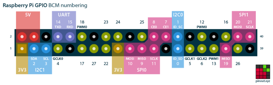
If you needed the SPI1 hardware, you’d pick different pins.
Reboot that sucker and another input device appears:
ll /dev/input/by-path/
total 0
lrwxrwxrwx 1 root root 9 Oct 18 10:00 platform-button@1a-event -> ../event0
lrwxrwxrwx 1 root root 9 Oct 18 10:00 platform-rotary@14-event -> ../event2
lrwxrwxrwx 1 root root 9 Oct 18 10:00 platform-soc:shutdown_button-event -> ../event1
As with the encoder device, the button device name includes the hex equivalent of the pin number: 26 decimal = 0x1a.
Run some code:
# Keypress from Raspberry Pi GPIO pin using evdev
# Add to /boot/config.txt
#  dtoverlay=gpio-key,gpio=26,keycode=83,label="KNOB"

import evdev

b = evdev.InputDevice('/dev/input/by-path/platform-button@1a-event')
print('Button device: {}'.format(b.name))

print(' caps: {}'.format(b.capabilities(verbose=True)))
print(' fd: {}'.format(b.fd))

for e in b.read_loop():
    print('Event: {}'.format(e))
    if e.type == evdev.ecodes.EV_KEY:
        print('Key {}: {}'.format(e.code,e.value))
Which produces this output:
Button device: button@1a
caps: {('EV_SYN', 0): [('SYN_REPORT', 0), ('SYN_CONFIG', 1)], ('EV_KEY', 1): [('KEY_KPDOT', 83)]}
fd: 3
Event: event at 1603036309.683348, code 83, type 01, val 01
Key 83: 1
Event: event at 1603036309.683348, code 00, type 00, val 00
Event: event at 1603036310.003329, code 83, type 01, val 00
Key 83: 0
Event: event at 1603036310.003329, code 00, type 00, val 00
All in all, that was easy …
