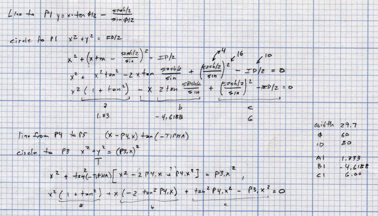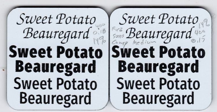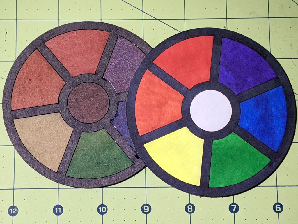
Having figured out how to intersect a line with a circle, I figured I could do it twice to put arcs on both the inside and the outside of each petal:
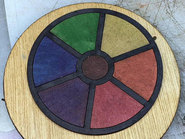
As before, scribbling markers on plain chipboard makes for a … subdued … coaster, so I tried chipboard with one white surface:

Much better.
Clamping the coaster produces a flatter result:
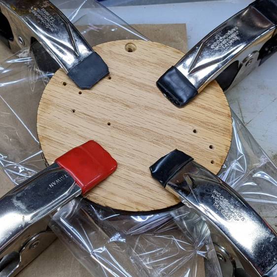
With the risk of squishing excess glue through the kerf:
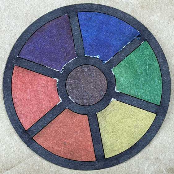
That’s the same coaster as in the first picture, carefully arranged with light reflecting off the flat glue surface. In real life, the nearly transparent glue doesn’t look nearly so awful, but smoothing much less glue than seems necessary across the bottom disk suffices.
The geometry doodle with the arcs:
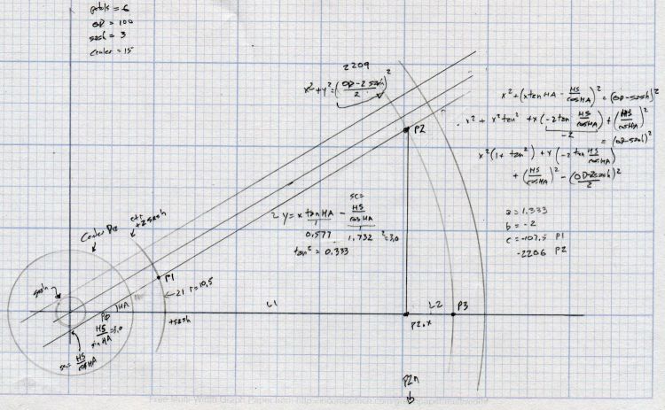
I suppose I should refactor the code with a quadratic solver returning a list of roots, but copypasta suffices for now.
The GCMC and Bash source code as a GitHub Gist:
| #!/bin/bash | |
| # Simple petals test piece | |
| # Ed Nisley KE4ZNU – 2022-07-01 | |
| Flags='-P 4 –pedantic' # quote to avoid leading hyphen gotcha | |
| SVGFlags='-P 4 –pedantic –svg –svg-no-movelayer –svg-opacity=1.0 –svg-toolwidth=0.2' | |
| # Set these to match your file layout | |
| ProjPath='/mnt/bulkdata/Project Files/Laser Cutter/Coasters/Source Code' | |
| LibPath='/opt/gcmc/library' | |
| ScriptPath=$ProjPath | |
| Script='Simple Petals.gcmc' | |
| [ -z "$1" ] && petals="6" || petals="$1" | |
| fn=Petals-$petals.svg | |
| echo Output: $fn | |
| gcmc $SVGFlags \ | |
| -D "NumPetals=$petals" \ | |
| –include "$LibPath" \ | |
| "$ScriptPath"/"$Script" > "$fn" | |
| // Simple Petals Test Piece | |
| // Ed Nisley KE4ZNU | |
| // 2022-07-12 Simplest possible petals | |
| layerstack("Frame","Petals","Rim","Base","Center","Tool1"); // SVG layers map to LightBurn colors | |
| //—– | |
| // Library routines | |
| include("tracepath.inc.gcmc"); | |
| include("tracepath_comp.inc.gcmc"); | |
| include("varcs.inc.gcmc"); | |
| include("engrave.inc.gcmc"); | |
| FALSE = 0; | |
| TRUE = !FALSE; | |
| //—– | |
| // Command line parameters | |
| // -D various useful tidbits | |
| // add unit to speeds and depths: 2000mm / -3.00mm / etc | |
| if (!isdefined("OuterDia")) { | |
| OuterDia = 100.0mm; | |
| } | |
| if (!isdefined("CenterDia")) { | |
| CenterDia = 25.0mm; | |
| } | |
| if (!isdefined("NumPetals")) { | |
| NumPetals = 6; | |
| } | |
| if (!isdefined("Sash")) { | |
| Sash = 5.0mm; | |
| } | |
| // Petal values | |
| PetalAngle = 360.0deg/NumPetals; // subtended by inner sides | |
| PetalHA = PetalAngle/2; | |
| PetalOD = OuterDia – 2*Sash; | |
| PetalID = CenterDia + 2*Sash; | |
| PetalOAL = OuterDia/2 – Sash – (Sash/2)/sin(PetalHA); | |
| //message("petalOAL: ",PetalOAL); | |
| // Find petal vertices | |
| P0 = [(Sash/2) / sin(PetalHA),0.0mm]; | |
| t1 = tan(PetalHA); | |
| sc = (Sash/2) / cos(PetalHA); | |
| if (P0.x < PetalID/2) { | |
| a = 1 + pow(t1,2); | |
| b = -2 * t1 * sc; | |
| c = pow(sc,2) – pow(PetalID/2,2); | |
| xp = (-b + sqrt(pow(b,2) – 4*a*c))/(2*a); | |
| xn = (-b – sqrt(pow(b,2) – 4*a*c))/(2*a); | |
| y = xp*t1 – sc; | |
| if (FALSE) { | |
| message("a: ",a); | |
| message("b: ",b); | |
| message("c: ",c); | |
| message("p: ",xp," n: ",xn," y: ",y); | |
| } | |
| P1 = [xp,y]; | |
| } | |
| else { | |
| P1 = P0; | |
| } | |
| a = 1 + pow(t1,2); | |
| b = -2 * t1 * sc; | |
| c = pow(sc,2) – pow(PetalOD/2,2); | |
| if (FALSE) { | |
| message("a: ",a); | |
| message("b: ",b); | |
| message("c: ",c); | |
| } | |
| xp = (-b + sqrt(pow(b,2) – 4*a*c))/(2*a); | |
| xn = (-b – sqrt(pow(b,2) – 4*a*c))/(2*a); | |
| y = to_mm(sqrt(pow(PetalOD/2,2) – pow(xp,2))); | |
| //message("p: ",xp," n: ",xn," y: ",y); | |
| P2 = [xp,y]; | |
| PetalWidth = 2*P2.y; | |
| P3 = [PetalOD/2,0.0mm]; | |
| if (FALSE) { | |
| message("P0: ",P0); | |
| message("P1: ",P1); | |
| message("P2: ",P2); | |
| message("P3: ",P3); | |
| } | |
| // Construct paths | |
| PetalPoints = {P1,P2}; | |
| OutArc = varc_cw([P2.x,-P2.y] – P2,PetalOD/2); | |
| OutArc += P2; | |
| PetalPoints += OutArc; | |
| if (P0 != P1) { | |
| PetalPoints += {[P1.x,-P1.y]}; | |
| InArc = varc_ccw(P1 – [P1.x,-P1.y],PetalID/2); | |
| InArc += [P1.x,-P1.y]; | |
| PetalPoints += InArc; | |
| } | |
| else { | |
| PetalPoints += {P0}; | |
| } | |
| //— Lay out the frame | |
| linecolor(0xff0000); | |
| layer("Frame"); | |
| if (CenterDia) { | |
| goto([CenterDia/2,0mm]); | |
| circle_cw([0mm,0mm]); | |
| } | |
| repeat(NumPetals;i) { | |
| a = (i-1)*PetalAngle; | |
| tracepath(rotate_xy(PetalPoints,a)); | |
| } | |
| goto([OuterDia/2,0]); | |
| circle_cw([0mm,0mm]); | |
| //— Lay out internal pieces for oriented cutting | |
| // baseplate | |
| layer("Base"); | |
| relocate([OuterDia + 2*Sash,0]); | |
| goto([OuterDia/2,0]); | |
| circle_cw([0mm,0mm]); | |
| // central circle | |
| if (CenterDia) { | |
| layer("Center"); | |
| relocate([OuterDia/2 + Sash,-(OuterDia – CenterDia)/2]); | |
| goto([CenterDia/2,0mm]); | |
| circle_cw([0mm,0mm]); | |
| } | |
| // petals | |
| layer("Petals"); | |
| repeat(NumPetals;i) { | |
| org = [PetalWidth/2 – OuterDia/2,-(OuterDia + Sash)]; | |
| relocate([(i-1)*(PetalWidth + Sash) + org.x,org.y]); | |
| tracepath(rotate_xy(PetalPoints,90deg)); | |
| } | |
| // Debugging by printf() | |
| if (FALSE) { | |
| layer("Tool1"); | |
| linecolor(0xff1f00); | |
| goto([Sash/2,0mm]); | |
| circle_cw([0mm,0mm]); | |
| goto(P0); | |
| circle_cw([0mm,0mm]); | |
| goto([0,0]); | |
| move([OuterDia/2,0]); | |
| goto([0,0]); | |
| move(OuterDia/2 * [cos(PetalHA),sin(PetalHA)]); | |
| goto(P2); | |
| move_r([0,-PetalWidth/2]); | |
| } |