Ed Nisley's Blog: Shop notes, electronics, firmware, machinery, 3D printing, laser cuttery, and curiosities. Contents: 100% human thinking, 0% AI slop.
Category: Software
General-purpose computers doing something specific
Level 9 must be 100% of the maximum motor current so the throttle can apply full power to get out of the way in a hurry.
The new and even more derated configuration allows small-step assist level selection for our usual riding, at the cost of an unused huge step to level 9 for the throttle:
The LC=18 line limits the maximum motor current to 18 A, rather than the rated 24 A, which may improve controller MOSFET longevity; reliable evidence is hard to come by. Controller failures seem to happen more often to riders who value jackrabbit acceleration on harsh terrain, so it may make little difference for road cyclists.
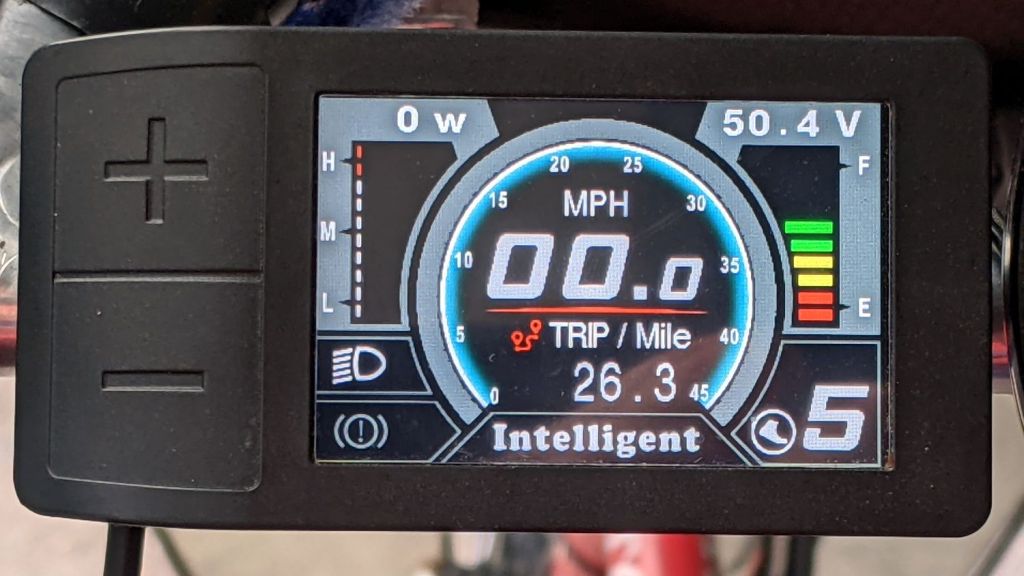
So level 5 now selects 75% × 20% = 15% of the motor’s nominal 750 W:
Tour Easy Bafang – display 26 mi
Call it 115 W: we’re both getting plenty of exercise!
In mostly reverse chronological order, here are various commands I’ve puzzled out:
#xsetwacom --verbose set "HUION Huion Tablet stylus" MapToOutput "DP1-8"
xsetwacom --verbose set "HUION Huion Tablet stylus" MapToOutput "DP-1-8"
#xsetwacom --verbose set "HUION Huion Tablet Pen stylus" MapToOutput "DP-1"
#xsetwacom --verbose set "Wacom Graphire3 6x8 Pen stylus" MapToOutput "DP-1"
#xsetwacom --verbose set "Wacom Graphire3 6x8 Pen stylus" MapToOutput "HEAD-0"
#xsetwacom --verbose set "Wacom Graphire3 6x8 Pen eraser" MapToOutput "DP-1"
#xsetwacom --verbose set "Wacom Graphire3 6x8 Pen eraser" MapToOutput "HEAD-0"
Over the last two years, the display name changed from DP-1 to DP-1-8 to DP1-8, and back to DP-1-8. I grew accustomed to this with the Wacom tablet (HEAD-0‽)and now know where to look, but I still have no idea of the motivation.
Aaaand the tablet’s stylus name? The Wacom names were stable, but the Huion names apparently come from the Department of Redundancy Department.
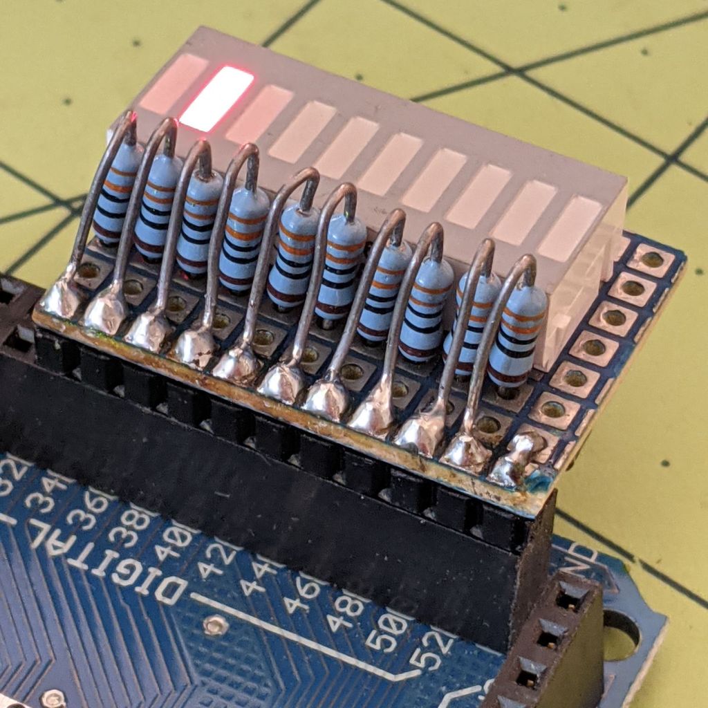
Kibitzing on a project involving an Arduino Mega (properly MEGA, but who cares?) with plenty of spare I/O pins led me to slap together a block of LEDs:
Arduino Mega Debugging LEDs
The excessive lead length on the 330 Ω resistors will eventually anchor scope probes syncing on / timing interesting program events.
Not that you have any, but they’re antique HP HDSP-4836 tuning indicators: RRYYGGYYRR. If you were being fussy, you might use 270 Ω resistors on the yellow LEDs to brighten them up.
A simple test program exercises the LEDs:
/*
  Debugging LED outputs for Mega board
  Ed Nisley - KE4ZNU
  Plug the board into the Digital Header pins 34-52 and GND
*/

byte LowLED = 34;
byte HighLED = 52;
byte ThisLED = LowLED;

//-----
void setup() {
  pinMode(LED_BUILTIN,OUTPUT);

  for (byte p = LowLED; p <= HighLED; p+=2)
    pinMode(p, OUTPUT);

//  Serial.begin(9600);
}

// -----
void loop() {
  digitalWrite(LED_BUILTIN,HIGH);

  digitalWrite(ThisLED, HIGH);
  delay(100);
  digitalWrite(ThisLED, LOW);
 // delay(500);

  ThisLED = (ThisLED < HighLED) ? (ThisLED + 2) : LowLED;

//  Serial.println(ThisLED);

  digitalWrite(LED_BUILTIN,LOW);
}
Nothing fancy, but it ought to come in handy at some point.
Being that type of guy, I turn my phone off during the night while it’s charging, turn it on for the next day’s adventures, and check the Google Play App Store to see which apps will get updates.
The vast machine learning / AI / whatever analyzing my every move still hasn’t figured out my morning ritual, so it desperately tries to sell me crap:
Google Play Store – app ad delay
My guess: those blank spots are placeholders for app ads, but, while the phone is busy scanning for malicious apps, the ad bidding process doesn’t complete fast enough to update the display before I see it.
FWIW, I had the Genuine NYS Covid-19 app installed for a while, but I very rarely go anywhere or see anybody, so it seemed to offer no net benefit.
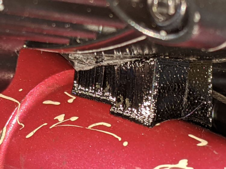
The original BBS02 reaction spacer for Gee’s Terry Symmetry didn’t work quite the way I expected:
Bafang BBS02 – reaction block displacement
The motor evidently vibrates enough to propel the block forward, shearing the double-sticky foam tape which was never intended to resist force in that plane. I thought the block was located at the point where the motor casing was tangent to the frame tube, so as to equalize the forces in both directions, but … nope.
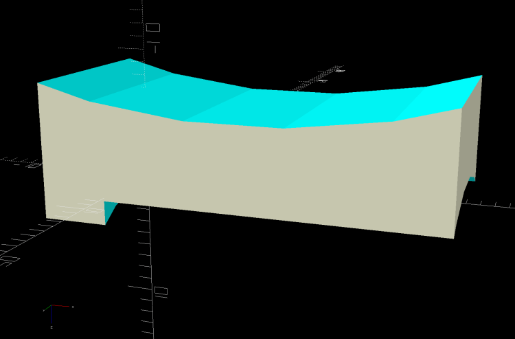
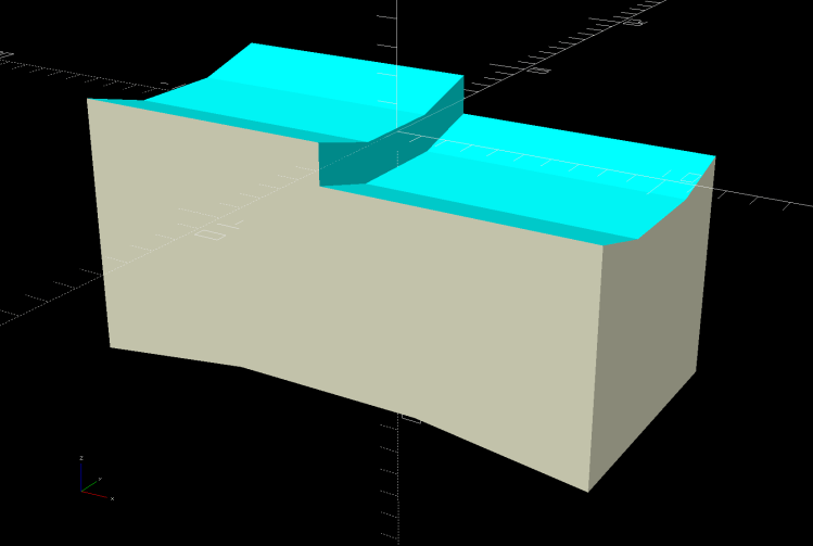
A revised design based on measurements informed by new knowledge:
Terry – Bafang motor spacer – improved – solid model
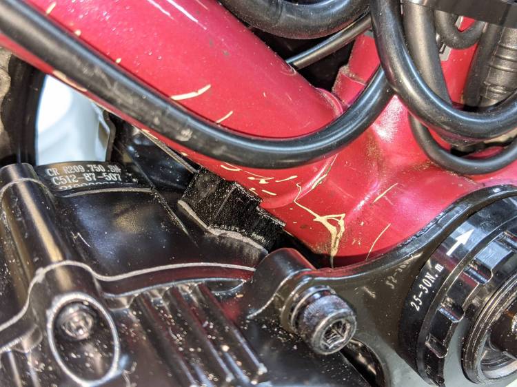
The upper curve is now symmetric and the whole block mounts more rearward under the bottom bracket lug, where some tedious work with a machinists square located the real tangent point:
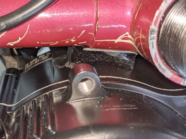
Bafang BBS02 – reaction block improvement
The motor sure doesn’t look like it’s tangent, but a dry fit showed all the curves laid against the case and tubes.
The brazing fillet means the step fitting the downtube can’t sit snug against the edge of the lug, but most of the reaction force should go through the section into the lug, near the center of the block.
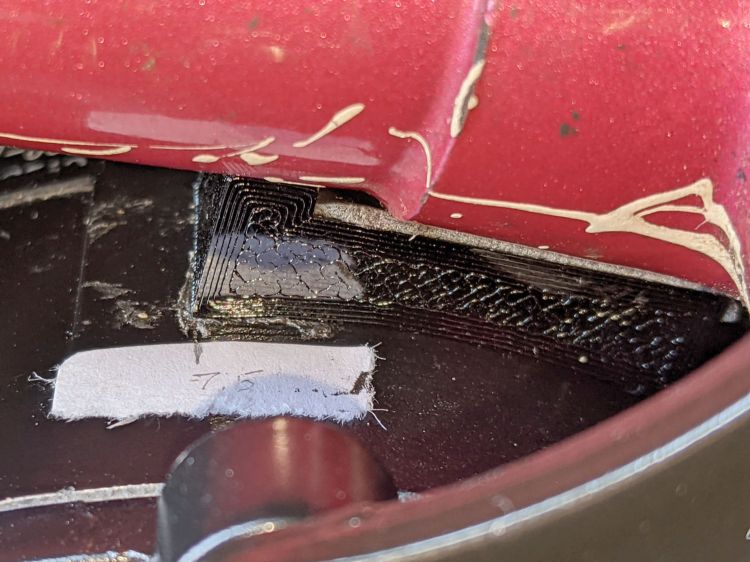
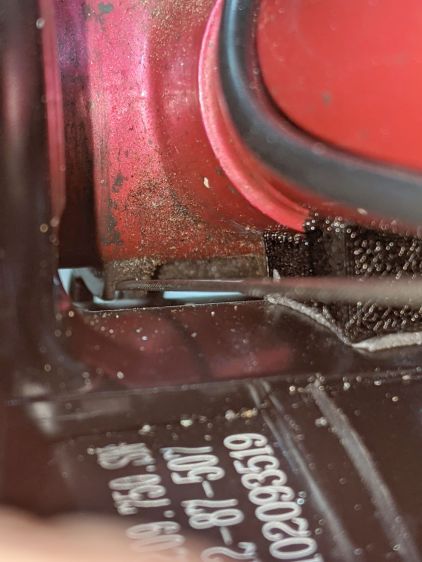
A crude marker will keep track of any motion:
Bafang BBS02 – reaction block marker
I think the symmetric curve against the motor has enough projection to keep the block from wandering off, even if I haven’t gotten the location exactly right.
Having seen a few bikes with amber “headlights” and being desirous of reducing the number of batteries on Mary’s bike, this seems like an obvious first step:
The rest of the code gets a few cleanups you’d expect when you compile code untouched for a few years using the latest OpenSCAD.
The markers are allegedly DOT rated, which matters not for my use case: SAEP2PCDOT.
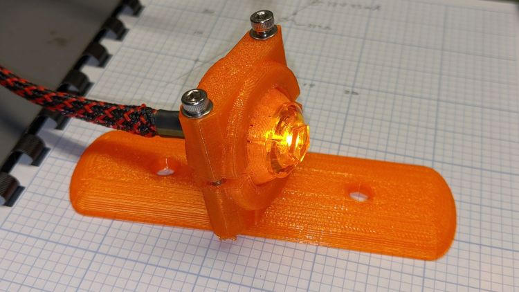
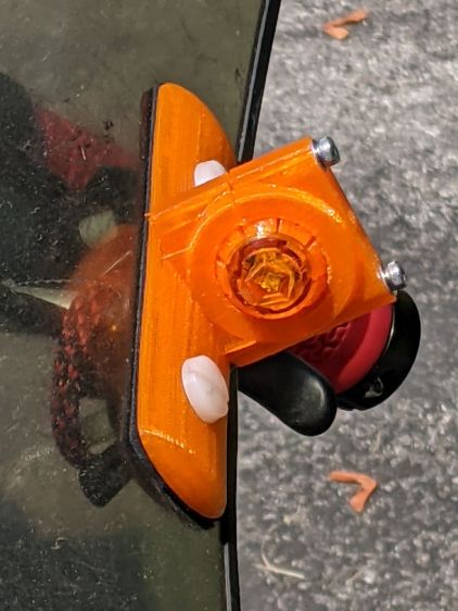
The mount is grossly overqualified for a wide-beam light with little need for aiming:
Fairing Mounted Side Marker – test light
Eventually, the marker should slip into a prealigned cylindrical holder, with a dab of epoxy to keep it there.
The lights are a buck apiece, so there’s no reason to form a deep emotional attachment. They are the usual poorly molded and badly assembled crap, although the next step up from a nominally reputable supplier is a factor of five more expensive.
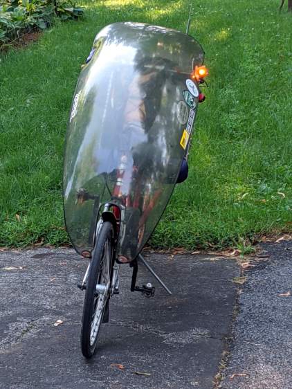
It’s generated for the left side of the fairing, although I think having a pair of them would improve conspicuity:
Fairing Mounted Side Marker – installed
Being automotive, it runs from a 12 V supply, which comes from a boost converter driven by the Bafang 6 V headlight output. The absurdity of bucking a 48 V lithium battery to a 6V switched headlight output, then boosting it to 12 V to drive a single amber LED with a 1.5 V forward drop does not escape me.
It’s possible to slice the lens off (using a lathe), remove / replace the resistor, then glue it back together, which would be worthwhile if you were intending to drive it from, say, an Arduino-ish microcontroller to get a unique blink pattern.
Given the overall lack of build quality, it might make more sense to slap a condenser lens in front of a Piranha LED.
The Terry Symmetry’s rear shift cable passes along the side of the downtube and through a plastic guide channel under the bottom bracket shell. The Bafang BBS02 motor must press against the bottom of the downtube, so the shift cable rubs against the top of the motor.
The solution is a small block shaped around the point of contact to cradle the downtube, the bottom bracket shell lug, and the motor case:
Terry – Bafang motor spacer – solid model
A strip of double-sided foam tape holds the block to the motor and the reaction force from the motor’s torque presses the block against the downtube:
Terry Bafang – motor reaction block
Seen from the other side, looking parallel to the shift cable, you can see the tight clearance:
Terry Bafang – shift cable clearance
The block holds the motor 8 mm from the downtube, just enough to give the cable some breathing room.
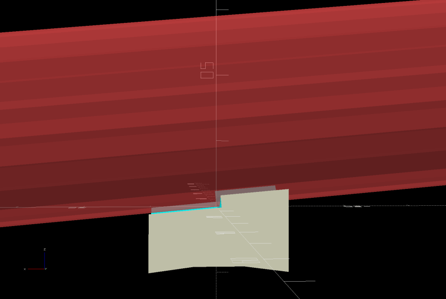
The block is slightly taller on its front end, because the motor doesn’t meet the downtube at a right angle:
Terry – Bafang motor spacer – tube angle – solid model
I determined the proper angle by taping waxed paper to the top of the motor, sticking a trial (non-angled) block to the downtube, coating its bottom surface with hot-melt glue, then squishing the motor against the block. The cooled glue was flush with the block on the rear and 1.8 mm thick on the front, a 5° angle over the 20 mm block.
Definitely easier than correctly figuring the geometry from first principles: tweak the model to include the measured thickness, compute the angle, tilt the tube, and print another block that fits like it grew there.
With the block in place and the motor held against the downtube, tighten the retaining nut against the “fixing plate” by giving it a few gentle whacks with a hammer, then tighten the jam nut.
The OpenSCAD source code snippet:
// Motor Reaction Block
// Holds motor away from downtube enough to miss rear shift wire

MotorOD = 111;              // motor frame dia
MotorMountRad = 85;         // BB spindle center to motor center
Space = 8.0;                // motor to frame space

Spacer = [20.0,DownTube[ID]/2,4*Space];
SpaceAngle = atan(1.8/Spacer.x);            // tilt due to non-right-angle meeting
echo(str("Spacer angle: ",SpaceAngle));

module MotorSpacer() {

    difference() {
        cube(Spacer,center=true);
        translate([0,0,DownTube[ID]/2])
            rotate([0,90 + SpaceAngle,0]) rotate(180/FrameSides)
                cylinder(d=DownTube[ID],h=DownTube[LENGTH],$fn=FrameSides,center=true);
        translate([DownTube[LENGTH]/2,0,DownTube[ID]/2 - DownTube[LENGTH]*sin(SpaceAngle)/2])       // concentric with ID
            rotate([0,90 + SpaceAngle,0]) rotate(180/FrameSides)
                cylinder(d=DownTube[OD],h=DownTube[LENGTH],$fn=FrameSides,center=true);
        translate([0,0,-(MotorOD/2 + Space)])
            rotate([90,0,0]) rotate(180/48)
                cylinder(d=MotorOD,h=2*Spacer.y,$fn=48,center=true);
    }

}
Mary’s Tour Easy didn’t need this block, because all the cables run elsewhere, but I did capture a piece of closed-cell foam between its vestigial downtube and the motor to prevent chafing.