The Smell of Molten Projects in the Morning

Ed Nisley's Blog: Shop notes, electronics, firmware, machinery, 3D printing, laser cuttery, and curiosities. Contents: 100% human thinking, 0% AI slop.

Category: Software

General-purpose computers doing something specific

  • Mini-Lathe Chuck Stops: CNC Pocketing

    Mini-Lathe Chuck Stops: CNC Pocketing

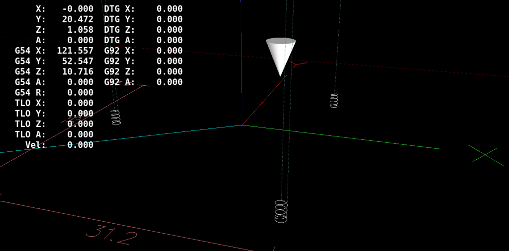
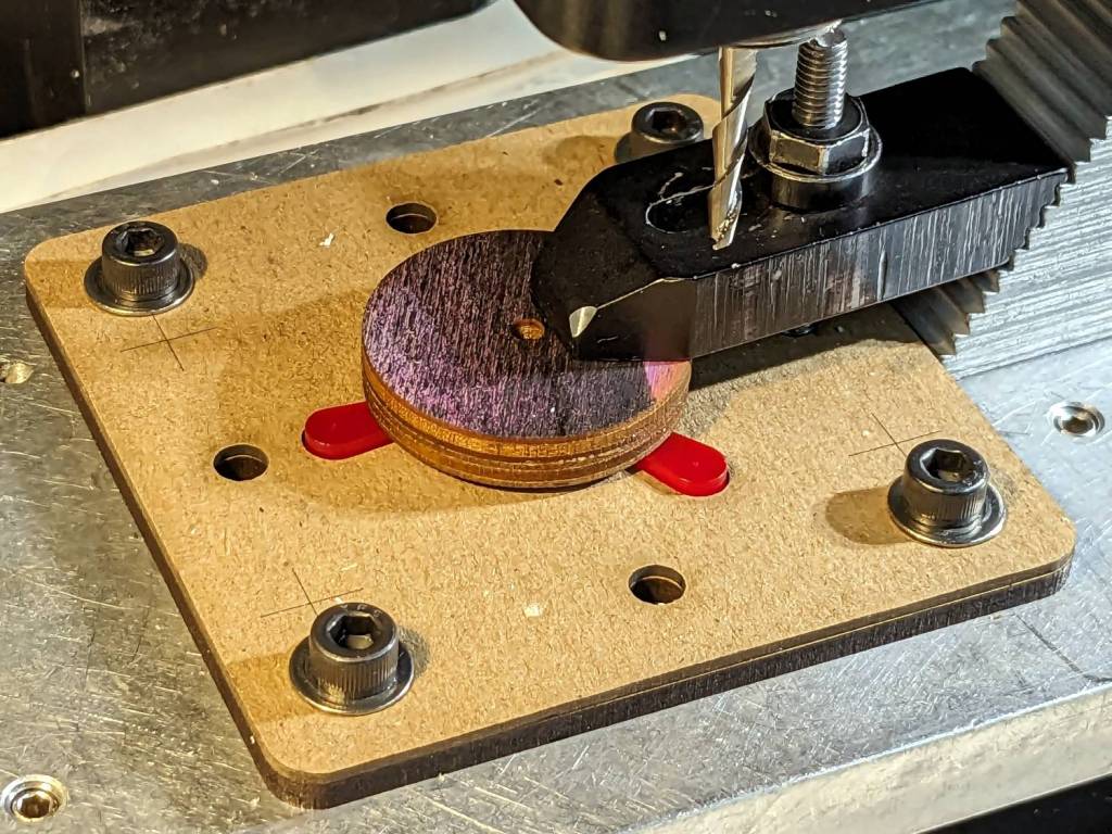
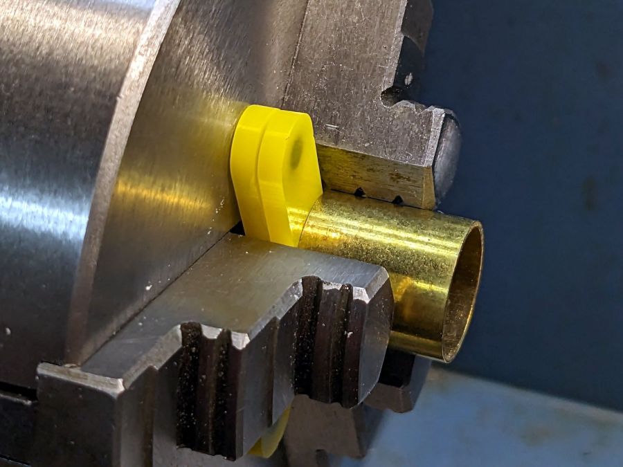
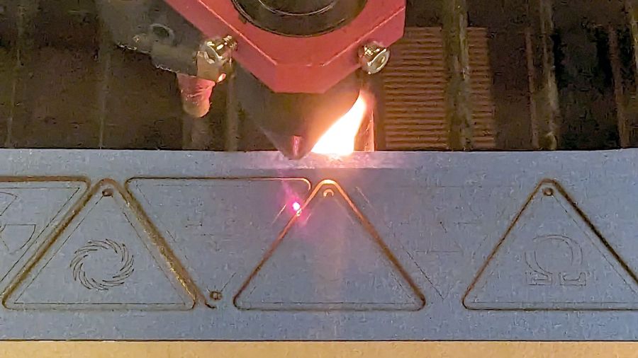
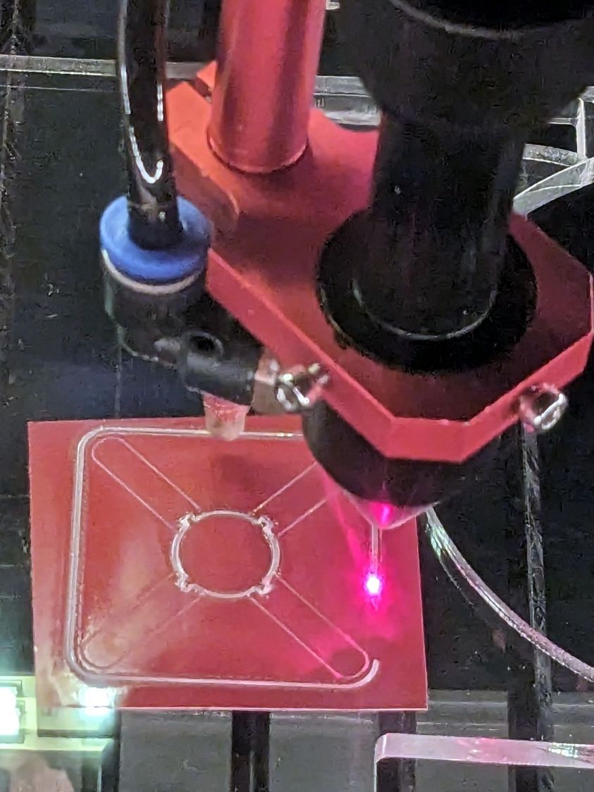
    With the fixture aligned and the chuck stop blank clamped down, all that’s left is to make three little pockets:

    Lathe Chuck Stop - Pocketing - LinuxCNC backplot
    Lathe Chuck Stop – Pocketing – LinuxCNC backplot

    Although Javascript may be the gom jabbar of programming, the blinding syntactic noise of raw G-Code puts you in a similar world of hurt:

    #<chuckrad>=20.000                  (radius to center of magnet)
    #<chuckjaws>=3                      (number of jaws)
    #<chuckang>=[360.0/#<chuckjaws>]    (angle between jaws)
    
    #<bitrad>=[2.900/2]                 (cutter radius)
    
    #<pocketrad>=[4.100/2]              (magnet pocket radius)
    #<pocketdeep>=2.200                 ( … depth)
    #<xoffs>=[#<pocketrad>-#<bitrad>]   (pocket center to cutter center)
    
    #<safez>=20.0                   (above all the clamps & gadgets)
    
    G21 G54 G80 G90 G94             (metric!)
    
    F600                            (full speed for the Sherline)
    
    G0 Z#<safez>
    

    Obviously, those magic numbers must match the laser-cut blanks, the magnets, the cutting bit in the spindle, the clamps on the table, the speed of the machine, and everything else you overlooked.

    So. Much. Pain.

    Knowing the angle to the current pocket, polar coordinate notation gets to the center point, with a jaunt in relative motion to the starting point for the helix into the pocket:

    #<ang>=[#<chuckang>/2]          (set starting angle)
    O100 REPEAT [#<chuckjaws>]
    
    G0 @#<chuckrad> ^#<ang>         (to hole center)
    G91                             (relative motion …)
    G0 X#<xoffs>                    ( … to helix start …)
    G90                             ( … and done)
    
    G0 Z0                           ( to surface)
    

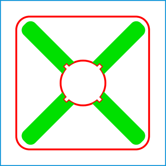
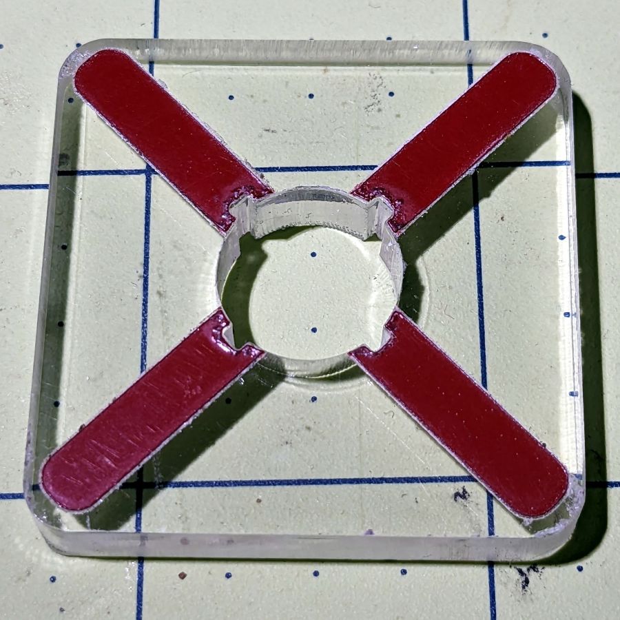
    Each pocket consists of a helix cut to the bottom, two clearing passes, and another helix back to the surface:

    G2 I[-#<xoffs>] Z[-#<pocketdeep>] P[1+FUP[#<pocketdeep>]]   (into hole)
    G2 I[-#<xoffs>] P2                                          (clean bottom)
    G3 I[-#<xoffs>] Z0 P[1+FUP[#<pocketdeep>]]                  (shave sides)
    

    That dance produced rounder pockets with cleaner bottoms than just a single helix down and a straight pull upward.

    Then set up for the next hole and clean up after the last one:

    G0 @#<chuckrad> ^#<ang>         (back to center)
    G0 Z#<safez>
    
    #<ang>=[#<ang>+#<chuckang>]     (set up next hole)
    O100 ENDREPEAT
    
    G0 Z[2*#<safez>]
    G0 X0 Y0
    
    M2
    

    I ran the Sherline XY axes at their 600 mm/min top speed, the spindle at 10 kRPM with a shiny new 3 mm (nominal!) cutter, ramped into the helix at ≅10° (on a 1 mm circle!), and it sliced the acrylic into nice chips without getting all melty.

    Unlike with Javascript, when you get something wrong in G-Code, you can hear the crash.

    The LinuxCNC pocketing code as a GitHub Gist:

    (Magnet pockets for laser-cut lathe chuck stops)
    (2023-07 Ed Nisley)
    #<chuckrad>=20.000 (radius to center of magnet)
    #<chuckjaws>=3 (number of jaws)
    #<chuckang>=[360.0/#<chuckjaws>] (angle between jaws)
    #<bitrad>=[2.900/2] (cutter radius)
    #<pocketrad>=[4.100/2] (magnet pocket radius)
    #<pocketdeep>=2.200 ( … depth)
    #<xoffs>=[#<pocketrad>-#<bitrad>] (pocket center to cutter center)
    #<safez>=20.0 (above all the clamps & gadgets)
    G21 G54 G80 G90 G94 (metric!)
    F600 (full speed for the Sherline)
    G0 Z#<safez>
    #<ang>=[#<chuckang>/2] (set starting angle)
    O100 REPEAT [#<chuckjaws>]
    G0 @#<chuckrad> ^#<ang> (to hole center)
    G91 (relative motion …)
    G0 X#<xoffs> ( … to helix start …)
    G90 ( … and done)
    G0 Z0 ( to surface)
    G2 I[-#<xoffs>] Z[-#<pocketdeep>] P[1+FUP[#<pocketdeep>]] (into hole)
    G2 I[-#<xoffs>] P2 (clean bottom)
    G3 I[-#<xoffs>] Z0 P[1+FUP[#<pocketdeep>]] (shave sides)
    G0 @#<chuckrad> ^#<ang> (back to center)
    G0 Z#<safez>
    #<ang>=[#<ang>+#<chuckang>] (set up next hole)
    O100 ENDREPEAT
    G0 Z[2*#<safez>]
    G0 X0 Y0
    M2
  • Mini-Lathe Chuck Stops: Pocketing Fixture

    Mini-Lathe Chuck Stops: Pocketing Fixture

    Putting pockets in the legs of the mini-lathe chuck stop blanks requires a fixture to align them in the Sherline mill:

    Lathe Chuck Stops - pocketing setup
    Lathe Chuck Stops – pocketing setup

    Because it need not withstand much lateral force and will get used only a dozen-ish times, the base is MDF and the stop alignment happens in three matching chipboard layers:

    Lathe Chuck Stops - Pocketing Fixture - LB layout
    Lathe Chuck Stops – Pocketing Fixture – LB layout

    The three stops (over on the right) are copy-pasta from the originals. A 0.1 mm outset in the chipboard (center) lets the acrylic shapes drop into the chipboard sheets with Good Enough™ alignment accuracy. The MDF layer (left) provides some overshoot comfort below the chipboard.

    The chipboard layers each have four alignment targets at (±30,±20):

    Lathe Chuck Stops - pocketing fixture touchoff
    Lathe Chuck Stops – pocketing fixture touchoff

    Touch off the lower-left target at (-30,-20) and G0 X30 Y30 should drop the laser dot in the middle of the upper-right target. With the (0,0) origin at the geometric center of the stop, LinuxCNC’s polar notation picks out the three pockets:

    G0 @20 ^-60
    G0 @20 ^180
    G0 @20 ^60
    

    The plywood disk under the Sherline’s clamp has a glued ring to put the clamping force out near the ends of the legs. I started with just the aluminum clamp, but the legs needed a bit more stability; a laser cutter makes impromptu widgets like that trivially easy.

    Next: write the G-Code to make the pockets.

    The LightBurn SVG layout as a GitHub Gist:

    Loading
    Sorry, something went wrong. Reload?
    Sorry, we cannot display this file.
    Sorry, this file is invalid so it cannot be displayed.

  • Mini-lathe Chuck Stops

    Mini-lathe Chuck Stops

    Having occasionally been in need of a lathe chuck stop, I finally cleared that project off the heap:

    Lathe Chuck Stops - demo setup
    Lathe Chuck Stops – demo setup

    These are definitely not up to commercial standards, but also don’t cost fifty bucks each. A trio of 4×2 mm neodymium disk magnets stick the stop to the chuck (and to each other) with enough force to hold it there, but not enough to make removing it a hassle.

    I imported the Z axis orthogonal view of the chuck jaws from the ball fixture for the running lights:

    Lathe Chuck Jaws - solid model axial
    Lathe Chuck Jaws – solid model axial

    Trace the right-side jaw, clean it up, put the tip a known distance from the origin, make a circular array, and draw a comfort circle the size of the chuck OD.

    The stop geometry comes from a hull wrapped around a circle a few millimeters larger than the 4 mm magnet (out 20 mm from the center) and a circle at the center sized so the hull clears the jaws:

    Lathe Chuck Stops - LB layout
    Lathe Chuck Stops – LB layout

    Then a small circle at the center allows me to drop the stop atop a known coordinate and rotate it around the circle, because the XY coordinate center is not at the geometric center.

    I cut out a few chipboard samples to verify the sizes, a few more from scrap acrylic to set up the pocketing operation, then half a dozen of each in cheerful kindergarten colors:

    Lathe Chuck Stops - on-lathe storage
    Lathe Chuck Stops – on-lathe storage

    The 5 mm stop is obviously too fragile for commercial success, but I figured it’ll survive long enough around here. Worst case, I can make another handful as needed.

    Although I have laser-engraved pockets in plywood, a few experiments in acrylic confirmed the surface finish is terrible and the depth control is iffy, at best. Given that I need a 2.2 mm deep pocket in 3 mm acrylic, a CNC mill seems the right way to poke the pockets:

    Lathe Chuck Stops - pocketing setup
    Lathe Chuck Stops – pocketing setup

    More on that tomorrow.

    The LightBurn SVG layout as a GitHub Gist:

    Loading
    Sorry, something went wrong. Reload?
    Sorry, we cannot display this file.
    Sorry, this file is invalid so it cannot be displayed.

  • Eyeglass Case Padding Redux

    Eyeglass Case Padding Redux

    Confronted with a nice metal eyeglass case that had lost its original liner, I traced the outline on paper and scanned it:

    Metal case outline
    Metal case outline

    Unlike the plastic Zenni cases, this one has nice straight edges, so:

    • Eyeball a LightBurn rectangle over the traced image
    • Round the corners to suit
    • Shrink it by a few millimeters to make it fit inside

    Then:

    • Add a perimeter line offset by the 6 mm required to cover the sides
    • Draw a dart in each corner to allow for bending the foam
    • Set the perimeter priority to 1 so it cuts last
    • Put the original outline to a tool layer to remind me how to do this the next time around

    Which looks like this:

    Metal case pad - LightBurn layout
    Metal case pad – LightBurn layout

    Then Fire The Laser into a sheet of EVA foam:

    Metal eyeglass case - padding cut
    Metal eyeglass case – padding cut

    Stuff it into the case, do another one in brown, and the result looks kinda like it should:

    Metal eyeglass case - padding installed
    Metal eyeglass case – padding installed

    That was easy …

  • Patio Chair Foot Adapters

    Patio Chair Foot Adapters

    Some years ago we acquired a free quartet of aluminum-frame patio chairs in need of new straps and feet. Eventually enough straps broke to force me to re-strap the things and I finally got around to replacing the badly worn OEM feet:

    Patio Chair Foot Adapter - OEM feet
    Patio Chair Foot Adapter – OEM feet

    The small drilled holes let me yoink most them out with sheet-metal screw attached to a slide hammer, then apply the Designated Prydriver to the most recalcitrant / broken ones.

    Some feet had worn enough to expose the aluminum tubes, but most had at least a thin layer of plastic:

    Patio Chair Foot Adapter - OEM foot erosion
    Patio Chair Foot Adapter – OEM foot erosion

    Obviously, I should have stripped and repainted the frames (if that’s possible, as they’re probably powder-coated), but a man’s gotta know his limitations and this job needed to get done.

    One might think patio furniture replacement feet are cheap & readily available, but no amount of keyword engineering produced search results with any degree of assured fit, so I conjured adapters for screw-in feet from the vasty digital deep:

    Patio Chair Foot Adapters - solid models
    Patio Chair Foot Adapters – solid models

    This was a long-awaited opportunity to explore the BOSL2 library and it worked wonderfully well. Each adapter is whittled from a huge hex nut with threads that perfectly fit the M8×1.25 stud, which stands vertically through the middle of the (slightly oval) bottom surface parallel to the floor.

    The front tubes have a 5° angle with respect to the vertical:

    Patio Chair Foot Adapter - front
    Patio Chair Foot Adapter – front

    And the rear tubes are 15° off:

    Patio Chair Foot Adapter - rear
    Patio Chair Foot Adapter – rear

    Each adapter has an orientation notch pointing toward the front of the front leg and the rear of the rear leg:

    Patio Chair Foot Adapter - orientation notch
    Patio Chair Foot Adapter – orientation notch

    I expected to apply adhesive on the inside and outside of the adapters, but they tapped firmly into place inside the legs and the studs screwed firmly into them, so we’ll see how they survive in actual use. I expect the studs to rust after a while, but that might not be the most awful thing ever to happen.

    The OpenSCAD source code as a GitHub Gist:

    // Patio chair foot adapter
    // Ed Nisley – KE4ZNU – 2023-06
    include <BOSL2/std.scad>
    include <BOSL2/threading.scad>
    LegAngles = [5,15];
    /* [Hidden] */
    ThreadThick = 0.25;
    ThreadWidth = 0.40;
    HoleWindage = 0.2;
    Protrusion = 0.1; // make holes end cleanly
    function IntegerMultiple(Size,Unit) = Unit * ceil(Size / Unit);
    ID = 0;
    OD = 1;
    LENGTH = 2;
    inch = 25.4;
    //———————-
    // Dimensions
    LegTube = [18.8 – HoleWindage,22.5,0];
    Stud = [8.0,1.25,10.0]; // M8x1.25 foot stud
    FlangeBase = 3.0;
    //———————–
    for (i=[0:len(LegAngles)-1]) {
    ang = LegAngles[i];
    FlangeIncr = LegTube[OD]*tan(ang);
    Flange = [Stud[0],LegTube[OD],FlangeBase + FlangeIncr];
    translate([i*1.5*Flange[OD],0,0])
    difference() {
    translate([0,0,0*-FlangeIncr/2])
    threaded_nut(2*Flange[OD],Stud[0],1.5*Stud[2],Stud[1],
    anchor=BOTTOM,bevel=false,$slop=0.2);
    rotate([0,ang,0]) {
    translate([0,0,FlangeBase + FlangeIncr/2])
    tube(4*Stud[2],2*Flange[OD],LegTube[ID]/2,
    anchor=BOTTOM);
    tube(4*Stud[2],2*Flange[OD],Flange[OD]/2,
    anchor=CENTER);
    }
    cube([Flange[OD],ThreadWidth,2*ThreadThick],anchor=BOTTOM+RIGHT);
    }
    }

  • Danger Zone Earrings: More SCP Warning Labels

    Danger Zone Earrings: More SCP Warning Labels

    More tinkering produced a full set of SCP warning labels in vector format suitable for laser cutting:

    SCP warning signs - LB layout
    SCP warning signs – LB layout

    The faint blue corresponds to the LightBurn tool layer, because you’ll want to assign your own cutting parameters.

    The circumscribing circle provides a convenient way to snap the pattern into something else, because the symbols in the middle are not necessarily centered around their geometric midpoint.

    Suiting action to drawings:

    SCP Earrings - black on yellow - cutting
    SCP Earrings – black on yellow – cutting

    The acrylic fire shows they’re called Danger Zone earrings for well and good reason!

    Anyhow, weeding the black vinyl produces crisp results:

    SCP Earrings - black on yellow - overview
    SCP Earrings – black on yellow – overview

    The fallout shelter symbol (top right) should have a circle around it, but that’s in the nature of fine tuning. It’s also not part of the SCP canon, but it kinda goes along with the radiation warning sign.

    They’re cut from transparent amber non-edge-lit acrylic with black vinyl PSA patterns:

    SCP Earrings - black on yellow - detail
    SCP Earrings – black on yellow – detail

    Still not enough to get me to go full-frontal Mr Clean.

    The LightBurn SVG layout as a GitHub Gist:

    Loading
    Sorry, something went wrong. Reload?
    Sorry, we cannot display this file.
    Sorry, this file is invalid so it cannot be displayed.

    I have no explanation for the different stroke widths, other than that SVG files seem to maintain a memory of every transformation applied to any object. LightBurn doesn’t use the stroke widths, so it should work out just fine.

  • Dripworks Micro-Flow Valve Knob Helper

    Dripworks Micro-Flow Valve Knob Helper

    One of the Dripworks Micro-Flow valves in Mary’s garden started spraying water through the mold mark in the middle of the bottom:

    Dripworks valve - bottom view
    Dripworks valve – bottom view

    The autopsy produced a handful of pieces and inconclusive results: no visible holes or cracks.

    Having replaced it with a new (and drilled out) valve, I scanned the underside of the severed valve knob, blew out the contrast, imported it into LightBurn, and got a reasonable approximation to the outline:

    LightBurn geometry over image
    LightBurn geometry over image

    A few more tweaks, weld the outline together, add some markers, and it’s ready for cutting:

    Dripworks valve helper - LB layout
    Dripworks valve helper – LB layout

    Having just done some earrings with PSA vinyl figures, I changed the (green) engraved layer to a kiss cut and Fired The Laser:

    Dripworks valve helper - cutting
    Dripworks valve helper – cutting

    The mess in the vinyl around the through cuts in the ¼ inch acrylic sheet suggest engraving will work better. Lesson learned.

    A few minutes of weeding produced a finger-friendly helper with scorches around the central ends of the vinyl:

    Dripworks valve helper
    Dripworks valve helper

    But it fits right over the knob, which was the whole point of the exercise:

    Dripworks valve helper - in use
    Dripworks valve helper – in use

    Now Mary can adjust the valve without squinting at obscure black-on-black shapes atop the knob.

    I decided keying the helper to the knob so it fit in only one orientation on the knob would be a hindrance, because there’s no easy way to determine their mutual orientation without the aforementioned squinting. Now it’s a matter of putting the helper over the knob, turning it at most a quarter-turn until it drops around the knob, then making another quarter of a turn to put the other red marks parallel to the hose: if it was on, it’s now off, and vice versa.

    After the PSA vinyl peels away, I’ll make another one with engraved lines and any other improvements.

    The LightBurn SVG layout as a GitHub Gist:

    Loading
    Sorry, something went wrong. Reload?
    Sorry, we cannot display this file.
    Sorry, this file is invalid so it cannot be displayed.