Ed Nisley's Blog: Shop notes, electronics, firmware, machinery, 3D printing, laser cuttery, and curiosities. Contents: 100% human thinking, 0% AI slop.
Category: Software
General-purpose computers doing something specific
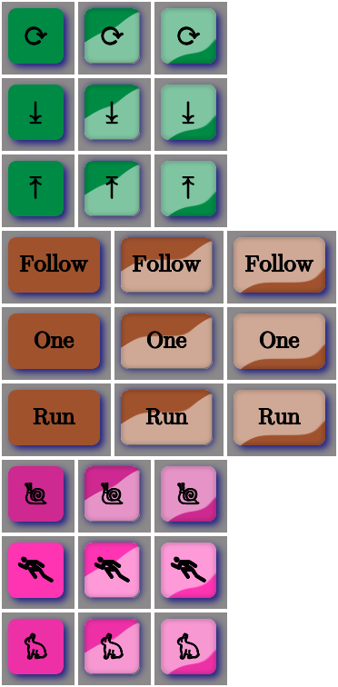
Aren’t those just the ugliest buttons you’ve ever seen?
The garish colors identify different functions, the crude shading does a (rather poor) job of identifying the states, and the text & glyphs should be unambiguous in context. Obviously, there’s room for improvement.
The point is that I can begin building the UI code that will slap those bitmaps on the Arduino’s touch-panel LCD while responding to touches, then come back and prettify the buttons as needed. With a bit of attention to detail, I should be able to re-skin the entire UI without building the data into the Arduino sketch, but I’ll start crude.
The mkAll.sh script that defines the button characteristics and calls the generator script:
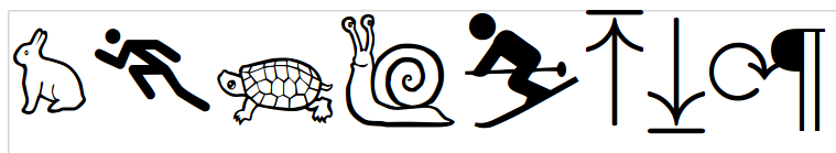
It turns out, for some reasons that aren’t relevant here, that I’ll be using the Adafruit Arduino LCD panel for the sewing machine control panel, at least to get started. In mulling that over, the notion of putting text on the buttons suggests using getting simple pictures with Unicode characters.
Herewith, some that may prove useful:
Needle stop up: ↥ = U+21A5
Needle stop up: ⤒=U+2912
Needle stop down: ⤓ = U+2913
Needle stop any: ↕ = U+2195
Needle stop any: ⟳ = U+27F3
Needle stop any: ⇅ = U+21C5
Rapid speed: ⛷ = U+26F7 (skier)
Rapid speed: 🐇 = U+1F407 (rabbit)
Slow speed: 🐢 = U+1F422 (turtle)
Dead slow: 🐌 = U+1F40C (snail)
Maximum speed: 🏃 = U+1F3C3 (runner)
Bobbin: ⛀ = U+26C0 (white draughts man)
Bobbin: ⛂ = U+26C2 (black draughts man)
Bobbin winding: 🍥 = U+1F365 (fish cake with swirl)
Of course, displaying those characters require a font with deep Unicode support, which may explain why your browser renders them as gibberish / open blocks / whatever. The speed glyphs look great on the Unicode table, but none of the fonts around here support them; I’m using the Droid font family to no avail.
Back when I started fiddling with 3D printed chain mail, the whole process from model to plastic worked wonderfully well. That continued with the larger sheets, but now, occasionally, the OpenSCAD model would produce weirdly sliced links. Depending on nothing repeatable, some links wouldn’t bridge correctly: the thread paths in the bottom layer across the gap would mysteriously stop just short of one pillar, return to the start, and leave an unsupported shelf that would, of course, fall into the gap.
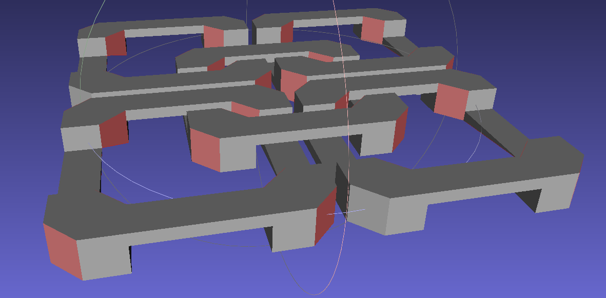
Shortly before Christmas, I managed to get a consistent failure that manifested differently: upon loading the STL file, Slic3r would quietly perform dozens of automatic corrections that (sometimes!) produced bizarrely distorted results. Feeding a failing model into Meshlab showed an irregular assortment of “self intersecting faces”, highlighted in red:
Chain Mail Square Armor – open – 2×2 – Meshlab self-intersecting faces
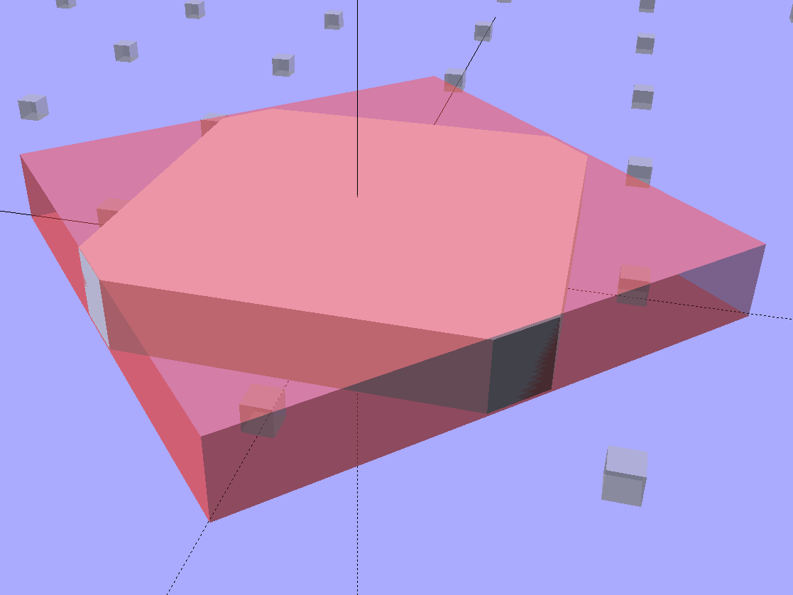
Although all four outer links in that image come from the same OpenSCAD module with identical sizes, they don’t all exhibit the same problem in the (nominally identical) faces on each of their four corners. In fact, those faces come from the intersection of two square slabs, carefully sized and positioned to avoid creating coincident planes:
Chain Mail Link – Outer shape
The central opening comes from a similar, slightly smaller, intersected-squares shape, but all four interior corner faces in each link show that they’re self-intersecting.
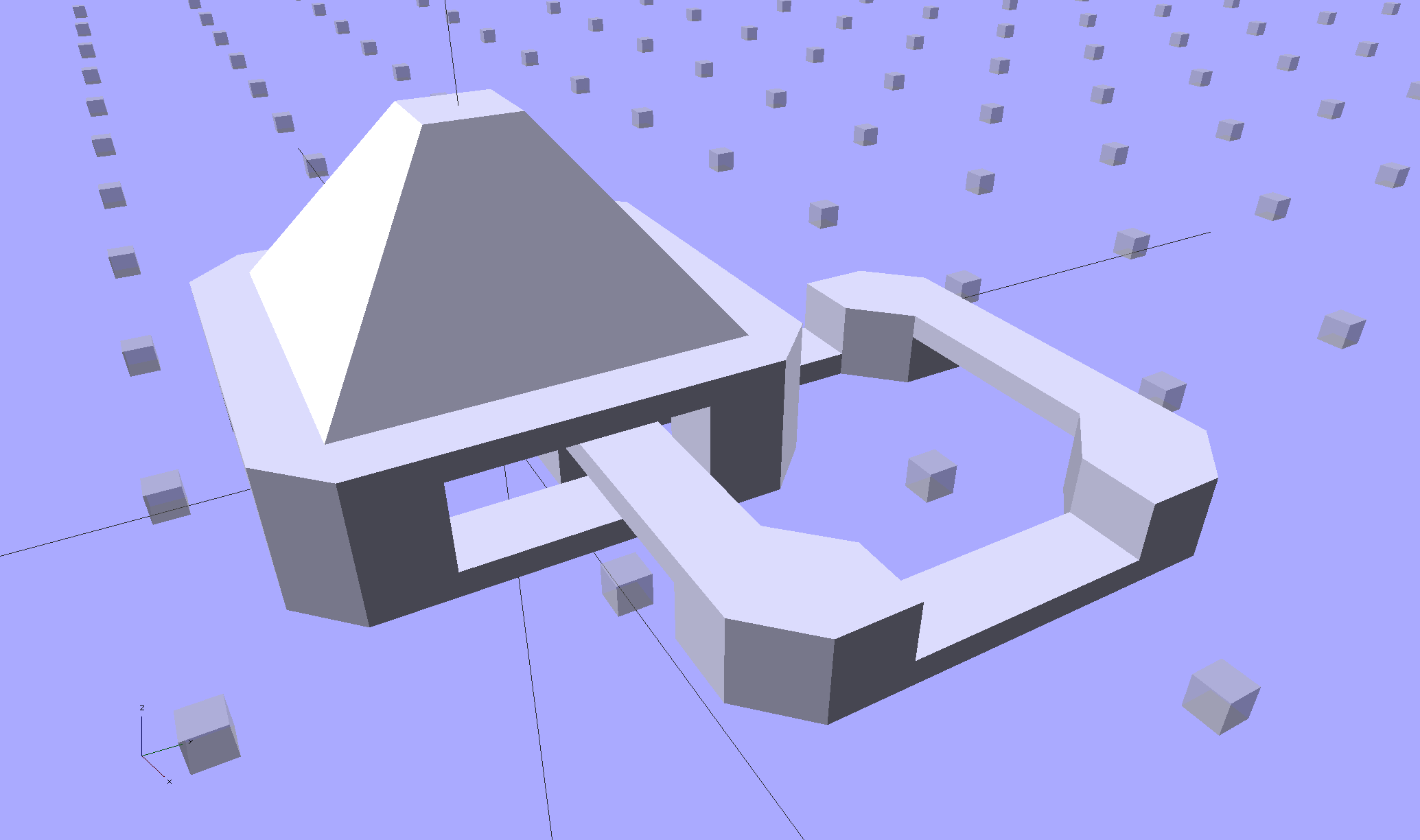
The STL looked fine in Meshlab, except for the highlit self-intersecting faces, so the geometry seemed OK.
When Slic3r autocorrected the “problems”, it apparently removed one vertex on the bottom surface of each bar, deleted the triangles connected to that vertex, then repaired the mesh to produce a delightfully symmetric pattern:
Chain Mail Square Armor – open – 2×2 – Slic3r corrections
Although the links are resolutely symmetric, Slic3r seemed happy with the identical vertices at the other end of the bar.
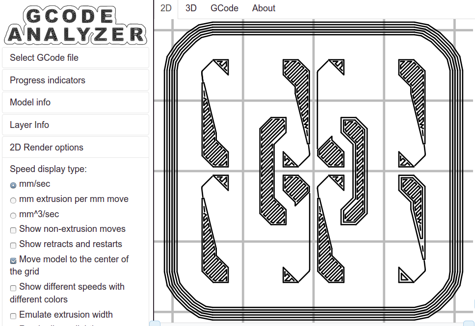
Unfortunately, the resulting G-Code won’t produce good links:
Chain Mail Square Armor – open – 2×2 – first layer G-code visualization
So, shortly before Christmas, I filed an issue on OpenSCAD’s Github repository.
The ensuing discussion showed that Meshlab flags faces as “self intersecting” when they have different vertices, even if their values are numerically equal, as well as vertices that differ by teeny amounts. Slic3r applies slightly different criteria to vertices & faces when it automagically corrects “problems” in the STL file, so that Meshlab may:
Highlight faces that don’t bother Slic3r
Apply the same highlight to faces that cause horrible problems
I don’t profess to understand much of that and may have the details wrong, but, apparently, OpenSCAD formerly used quantized coordinates that ensured all vertices within a tiny volume would have the same numeric value. In particular, all three faces that meet at a common point would, in fact, have numerically equal coordinate values for that point. The STL file format consists of a list of separate triangles, each with three coordinates for each of the three axes, and (without quantization) it was entirely possible for each of the three triangles with a common point to have three very slightly different positions for that point.
In theoretic terms, quantized coordinates cause horrible problems during geometric manipulation, because numeric values that aren’t exact can make repeated transformations come out wrong; running an object through a transformation and it’s inverse might not yield an object identical to the original one.
In practical terms, it seems that slicers and STL repair algorithms can reach incorrect conclusions based on minute differences produced by floating-point operations and numeric-to-text conversions. Those differences depend on slight changes in position, rotation, and size, so doing anything to the model produces completely different results.
That notwithstanding, the day after Christmas brought a new OpenSCAD version that uses quantized coordinates. A bit of rummaging in the source shows that the 3D grid (defined in src/grid.h) isn’t all that coarse:
const double GRID_FINE = 0.00000095367431640625;
STL files don’t carry units, so that could be in either millimeters (the Slic3r / RepRap convention) or inches (Sketchup, but we won’t go there). It’s exactly 1/10242, in case you were wondering, which produces a 5% speedup in the geometry engine compared to the more human-readable 1/10002.
With that commit in hand, all the chain mail links slice perfectly again.
I recently exhumed an Iomega 500 GB Home Network Hard Drive (model MDHD-500-N) from the Big Box o’ Drives, with the intent of dumping video files from the Sony HDR-AS30 helmet camera thereupon.
Remember Iomega of ZIP Drive fame? Seems EMC Borged ’em a while back, collided with Lenovo, discarded all the old hardware support, and that’s the end of that story.
Exhuming the setup password from my backup stash wasn’t worth the effort, so I experimentally determined that holding the Reset switch closed while turning the drive on blows away the existing configuration. It woke up, asked for an IP address, got 192.168.1.52 from the DHCP server (you can find that by checking the router’s tables), and popped up the administration console at 192.168.1.52:80 as you’d expect.
The userid will always be admin, but you can change the password from admin to whatever you like; you may safely assume I have done somewhat better than what you see below.
Twiddling the configuration through the IOmega web-based console:
Device name: IOMEGA-500MB (for lack of anything more creative)
Group name: WHATSMYNET
Password: not-admin
Drag the date/time into the current millennium
Time Zone: GMT-5:00
Time Server: 0.us.pool.ntp.org
Static IP: 192.168.1.10 (suitable for my network)
Gateway & DNS as appropriate
Windows File Sharing enabled for the PUBLIC directory
FTP turned off
Sleep time: 10 minutes
Changing either the IP address or the password requires logging in again, of course.
I reformatted the drive, just to be sure.
Then, after a bit of Googling to remember how all this works…
A line in /etc/hosts (left over from the last time I did this) gives the new static IP address:
192.168.1.10 nasty
Install the cifs-utils package to enable mounting the drive.
Create a mount point:
sudo mkdir /mnt/video
Create a file (/root/.nas-id) holding the super-secret credentials used to gain access to the drive:
domain=WHATSMYNET
username=ed
password=not-admin
Then restrict the file to the eyes of the root user:
sudo chmod 700 /root/.nas-id
It’s not clear that the username or domain really make any difference in this situation, but there they are.
Define where and how to mount the network drive with a new line at the bottom of /etc/fstab, which refers to the aforementioned super-secret credentials file:
Mounting it with my userid gives the shared directories & files proper permissions for me (and nobody else, not that anybody else around here cares).
So the manual mounting process looks like this:
sudo mount /mnt/video
Adding the user mount option would eliminate the sudo, but manual mounting won’t be necessary after a normal boot when the automagic startup script does the deed.
The drive must have the noauto attribute to prevent the upstart Pachinko machine from trying to mount the network drives before the network comes up. Actually mounting the drive at the proper time requires an additional line in /etc/init/local.conf:
description "Stuff that should be in /etc/rc.local"
author "Ed Nisley - KE4ZNU"

start on (local-filesystems and net-device-up IFACE=em1)
stop on shutdown

emits nfs-mounted

script

logger Starting local init...

logger Mounting NFS (and CIFS) filesystems
mount /mnt/bulkdata
mount /mnt/userfiles
mount /mnt/diskimages
mount /mnt/music
mount /mnt/video
initctl emit nfs-mounted
logger Ending local init

end script
The reason the drive wound up in the Big Box o’ Hard Drives was its lethargic transfer speed; copying a 4 GB video file from either the MicroSDXC card (via an SD adapter) or the previous 750 GB USB-attached hard drive to the IOmega NAS trundles along at a little over 6 MB/s. The camera stores 25 Mb/s = 3 MB/s of data in 1080p @ 60 fps, so figure 1/2 hour of copying per hour of riding. The USB drive can write data from the aforementioned MicroSDXC card at 18 MB/s, so the card and USB interface aren’t the limiting factors.
I’m not (generally) in a big hurry while copying files from the camera’s SD card, because that’s now automated:
#!/bin/sh
thisdate=$(date --rfc-3339=date)
echo Date is [$thisdate]
# IOmega NASalready mounted as /mnt/video in fstab
mkdir /mnt/video/$thisdate
sudo mount -o uid=ed /dev/sdb1 /mnt/part
rsync -ahu --progress /mnt/part/MP_ROOT/100ANV01/ /mnt/video/$thisdate
if [ $? -eq 0 ] ; then
 rm /mnt/part/MP_ROOT/100ANV01/*
 sudo umount /mnt/part
fi
I’ve been discarding the oldest month of videos as the USB hard drive fills up, which will happen a bit more often than before: the drive’s 466 GB can hold barely 35 hours of ride video.
Another nine hours of printing produced a second 9×13 link chain mail armor sheet that simply begged to be joined with the first. Snipping a connecting link on one sheet and attempting to thread it through the armor button on the other didn’t work nearly as well as I expected, because the pillars on the open links don’t quite pass through the slot in the side of the armor button links:
Chain Mail Armor – 4 sided
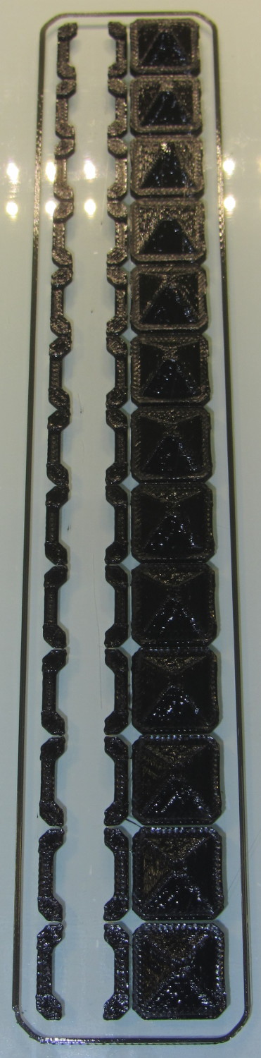
So I summoned joiner links from the digital deep:
Chain Mail Armor – Sheet Joiners
Those are standard armor button links, split at the cross bar level, then laid out along the Y axis. The cap bridges across the link just as it does on the chain mail sheets, so, when they’re glued back together, the result should be exactly like a solid link. There’s no room for alignment pins and, frankly, I wouldn’t fiddle with two dozen filament snippets anyway.
The OpenSCAD code below produces joiners that work for the square arrangement, not the diamond, but that’s in the nature of fine tuning.
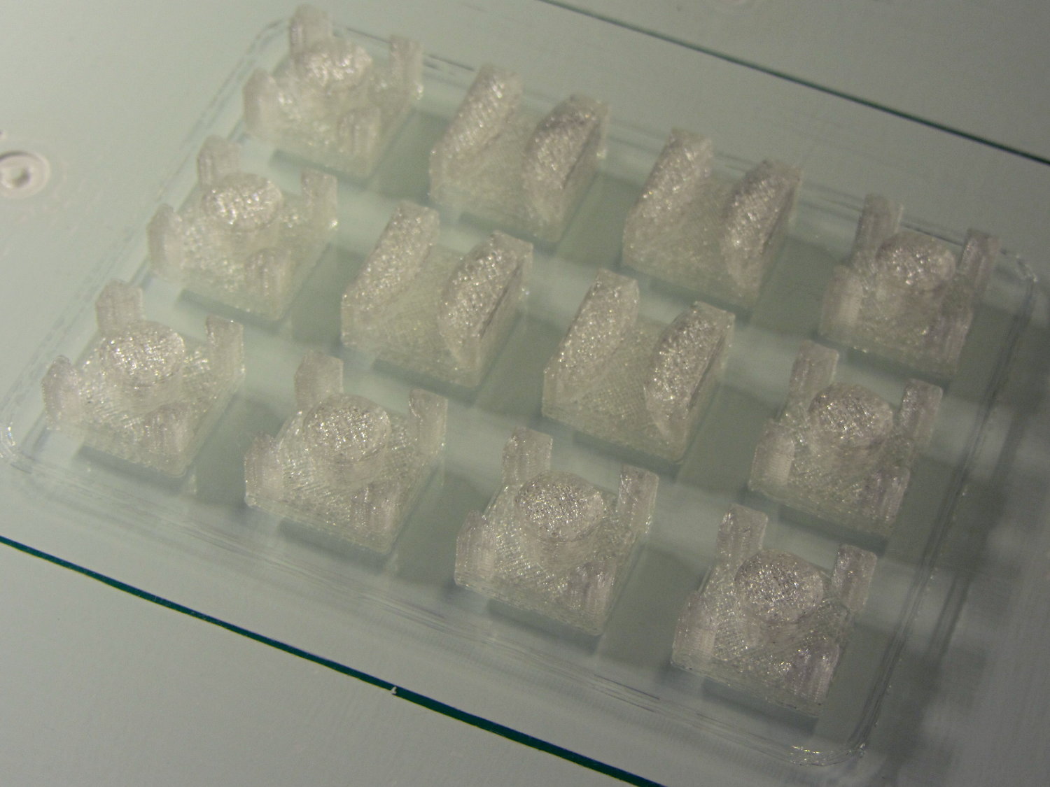
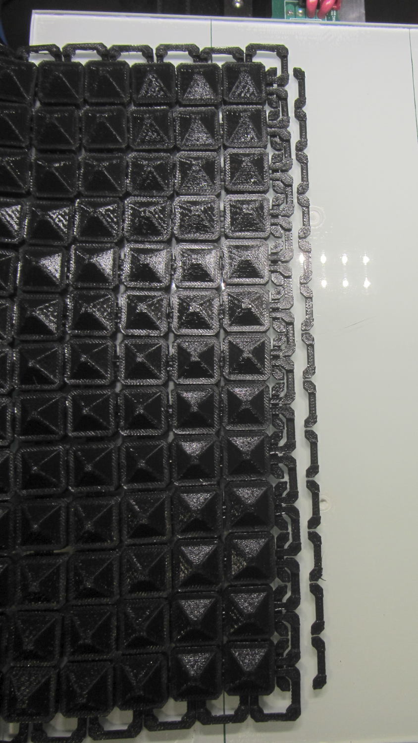
When I saw them pasted to the platform, just like the model:
Chain Mail Armor – joiners on platform
It occurred to me that I could pop the caps off, then lay the sheets in position, aligned on the underlying joiner half-links. Here’s the first sheet over the left set of bars:
Chain Mail Armor – sheet and joiners on platform
Then glue the armor caps in place:
Chain Mail Armor – joiner with solvent glue
Four dots of IPS #4 solvent glue, dispensed from a fine copper tube serving as a pipette, wet the four pillars of the joiner’s two bottom bars. I dotted each pillar to begin softening the PLA, paused for a breath, wet them again to leave enough solvent to bite into the bottom of the armor cap, pressed the cap in place, tweaked the alignment with tweezers, then pressed downward for maybe five seconds. Although the joiner link has no inherent alignment features, there’s also not much room to slide around and it worked surprisingly well.
Repeat that trick dozen times and you’re done. The aggravation scales as the square root of the overall sheet size, so it’s not as awful as assembling every single link, but it’s definitely a task for the low-caffeine part of the day.
One bottom bar came loose when I showed the result at the MHVLUG meeting, but the bar reappeared and I glued it again easily enough. I’ve now printed several spare joiners, Just In Case.
The bottom bars aren’t firmly affixed to the platform after it cools and they dislodge fairly easily: that’s how I get larger models off: let everything cool, then simply lift the plastic off. If I were joining sheets on a regular basis, I’d conjure a fixture to hold the sheets and joiner caps in position, probably with the sheets upside down, then glue the bars atop the inverted caps. That could get messy.
Perhaps a special holder to capture the bars in the proper alignment, maybe with pins matching the square openings at the corners, would help?
This is a trial fit before gluing that’s visually indistinguishable from the final product:
Chain Mail Armor – joined sheets on platform
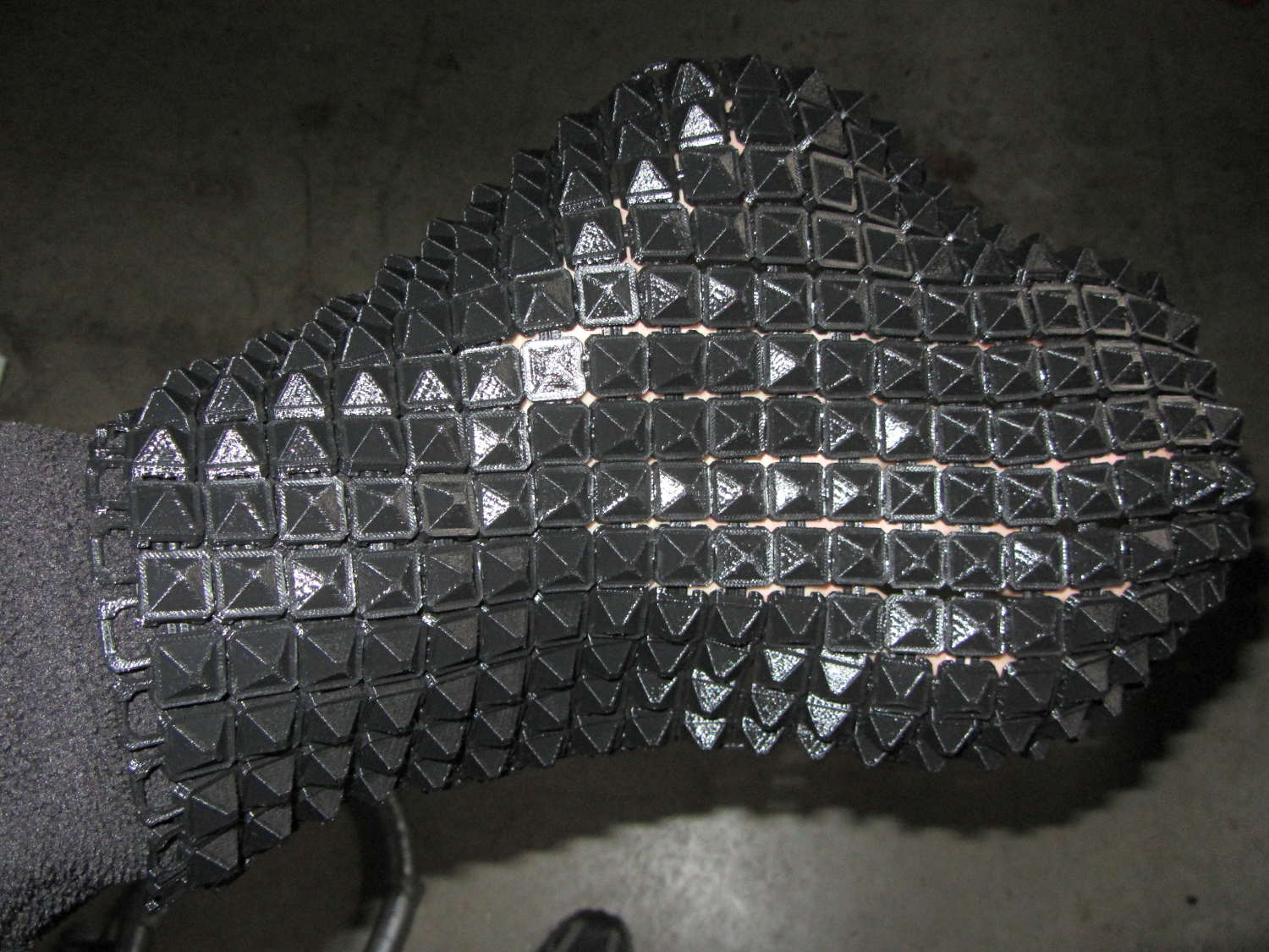
It’s not actually fabric, but it’s sufficiently bendy to cover a hand:
Chain Mail Armor – joined sheet draped on hand
The thing just cries out to be fondled…
There’s a quarter kilogram of plastic in that 8×12 inch = 200×310 mm sheet that almost used up the last of the black PLA spool.
Remember: you must tweak the OpenSCAD code to match your extruder settings, export a suitable STL file, get really compulsive about platform alignment, use hairspray / glue stick to boost platform adhesion, and have no qualms about an all-day print run. You can’t just slice a random STL file produced for a different printer, because the link dimensions come directly from the printer’s capabilities: one size does not fit all.
The OpenSCAD source code [Update: This is the refactored version.]:
// Chain Mail Armor Buttons
// Ed Nisley KE4ZNU - December 2014
Layout = "Build"; // Link Button LB Joiner Joiners Build
//-------
//- Extrusion parameters must match reality!
// Print with 1 shell and 2+2 solid layers
ThreadThick = 0.20;
ThreadWidth = 0.40;
HoleWindage = 0.2;
Protrusion = 0.1*ThreadThick; // make holes end cleanly
function IntegerMultiple(Size,Unit) = Unit * ceil(Size / Unit);
//-------
// Dimensions
//- Set maximum sheet size
SheetSizeX = 50; // 170 for full sheet on M2
SheetSizeY = 60; // 230
//- Diamond or rectangular sheet?
Diamond = false; // true = rotate 45 degrees, false = 0 degrees for square
BendAround = "X"; // X or Y = maximum flexibility *around* designated axis
Cap = true; // true = build bridge layers over links
Armor = true && Cap; // true = build armor button atop (required) cap
ArmorThick = IntegerMultiple(6,ThreadThick); // height above cap surface
// Link bar sizes
BarWidth = 6 * ThreadWidth;
BarThick = 4 * ThreadThick;
BarClearance = 5*ThreadThick; // vertical clearance above & below bars
//-- Compute link sizes from those values
// Absolute minimum base link: bar width + corner angle + build clearance around bars
// rounded up to multiple of thread width to ensure clean filling
BaseSide = IntegerMultiple((4*BarWidth + 2*BarWidth/sqrt(2) + 3*(2*ThreadWidth)),ThreadWidth);
BaseHeight = 2*BarThick + BarClearance; // both bars + clearance
echo(str("BaseSide: ",BaseSide," BaseHeight: ",BaseHeight));
echo(str(" Base elements: ",4*BarWidth,", ",2*BarWidth/sqrt(2),", ",3*(2*ThreadWidth)));
echo(str(" total: ",(4*BarWidth + 2*BarWidth/sqrt(2) + 3*(2*ThreadWidth))));
BaseOutDiagonal = BaseSide*sqrt(2) - BarWidth;
BaseInDiagonal = BaseSide*sqrt(2) - 2*(BarWidth/2 + BarWidth*sqrt(2));
echo(str("Outside diagonal: ",BaseOutDiagonal));
//- On-center distance measured along coordinate axis
// the links are interlaced, so this is half of what you think it should be...
LinkOC = BaseSide/2 + ThreadWidth;
LinkSpacing = Diamond ? (sqrt(2)*LinkOC) : LinkOC;
echo(str("Base spacing: ",LinkSpacing));
//- Compute how many links fit in sheet
MinLinksX = ceil((SheetSizeX - (Diamond ? BaseOutDiagonal : BaseSide)) / LinkSpacing);
MinLinksY = ceil((SheetSizeY - (Diamond ? BaseOutDiagonal : BaseSide)) / LinkSpacing);
echo(str("MinLinks X: ",MinLinksX," Y: ",MinLinksY));
NumLinksX = ((0 == (MinLinksX % 2)) && !Diamond) ? MinLinksX + 1 : MinLinksX;
NumLinksY = ((0 == (MinLinksY % 2) && !Diamond)) ? MinLinksY + 1 : MinLinksY;
echo(str("Links X: ",NumLinksX," Y: ",NumLinksY));
//- Armor button base
CapThick = 4 * ThreadThick; // at least 3 layers for solid bridging
ButtonHeight = BaseHeight + BarClearance + CapThick;
echo(str("ButtonHeight: ",ButtonHeight));
//- Armor ornament size & shape
// Fine-tune OD & ID to suit the number of sides...
ArmorSides = 4;
ArmorAngle = true ? 180/ArmorSides : 0; // true -> rotate half a side for best alignment
TotalHeight = ButtonHeight + ArmorThick;
echo(str("Overall Armor Height: ",TotalHeight));
ArmorOD = 1.1 * BaseSide; // tune for best base fit
ArmorID = 10 * ThreadWidth; // make the tip blunt & strong
//-------
module ShowPegGrid(Space = 10.0,Size = 1.0) {
RangeX = floor(95 / Space);
RangeY = floor(125 / Space);
for (x=[-RangeX:RangeX])
for (y=[-RangeY:RangeY])
translate([x*Space,y*Space,Size/2])
%cube(Size,center=true);
}
//-------
// Create link with armor button as needed
module Link(Topping = false) {
LinkHeight = (Topping && Cap) ? ButtonHeight : BaseHeight;
render(convexity=3)
rotate((BendAround == "X") ? 90 : 0)
rotate(Diamond ? 45 : 0)
union() {
difference() {
translate([0,0,LinkHeight/2]) // outside shape
intersection() {
cube([BaseSide,BaseSide,LinkHeight],center=true);
rotate(45)
cube([BaseOutDiagonal,BaseOutDiagonal,LinkHeight],center=true);
}
translate([0,0,(BaseHeight + BarClearance - Protrusion)/2])
intersection() { // inside shape
cube([(BaseSide - 2*BarWidth),
(BaseSide - 2*BarWidth),
(BaseHeight + BarClearance + Protrusion)],
center=true);
rotate(45)
cube([BaseInDiagonal,
BaseInDiagonal,
(BaseHeight + BarClearance + Protrusion)],
center=true);
}
translate([0,0,((BarThick + 2*BarClearance)/2 + BarThick)]) // openings for bars
cube([(BaseSide - 2*BarWidth - 2*BarWidth/sqrt(2)),
(2*BaseSide),
BarThick + 2*BarClearance],
center=true);
translate([0,0,(BaseHeight/2 - BarThick)])
cube([(2*BaseSide),
(BaseSide - 2*BarWidth - 2*BarWidth/sqrt(2)),
BaseHeight],
center=true);
}
if (Topping && Armor)
translate([0,0,(ButtonHeight - Protrusion)]) // sink slightly into the cap
rotate(ArmorAngle)
cylinder(d1=ArmorOD,
d2=ArmorID,
h=(ArmorThick + Protrusion),
$fn=ArmorSides);
}
}
//-------
// Create split buttons to join sheets
module Joiner() {
translate([-LinkSpacing,0,0])
difference() {
Link(false);
translate([0,0,BarThick + BarClearance + TotalHeight/2 - Protrusion])
cube([2*LinkSpacing,2*LinkSpacing,TotalHeight],center=true);
}
translate([LinkSpacing,0,0])
intersection() {
translate([0,0,-(BarThick + BarClearance)])
Link(true);
translate([0,0,TotalHeight/2])
cube([2*LinkSpacing,2*LinkSpacing,TotalHeight],center=true);
}
}
//-------
// Build it!
ShowPegGrid();
if (Layout == "Link") {
Link(false);
}
if (Layout == "Button") {
Link(true);
}
if (Layout == "LB") {
Link(true);
translate([LinkSpacing,LinkSpacing,0])
Link(false);
}
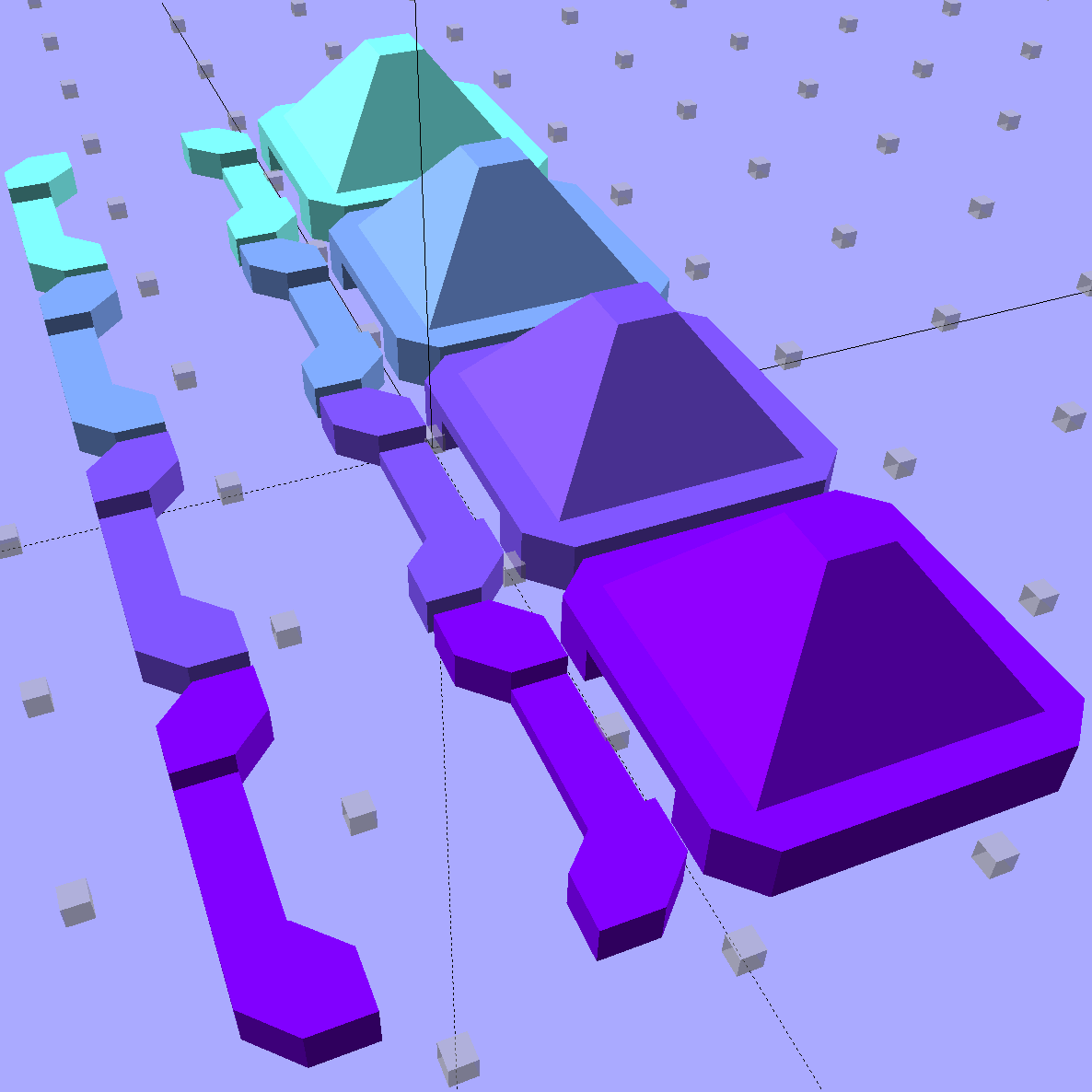
if (Layout == "Build")
for (ix = [0:(NumLinksX - 1)],
iy = [0:(NumLinksY - 1)]) {
x = (ix - (NumLinksX - 1)/2)*LinkSpacing;
y = (iy - (NumLinksY - 1)/2)*LinkSpacing;
translate([x,y,0])
color([(ix/(NumLinksX - 1)),(iy/(NumLinksY - 1)),1.0])
if (Diamond)
Link((ix + iy) % 2); // armor at odd,odd & even,even points
else
if ((iy % 2) && (ix % 2)) // armor at odd,odd points
Link(true);
else if (!(iy % 2) && !(ix % 2)) // connectors at even,even points
Link(false);
}
if (Layout == "Joiner")
Joiner();
if (Layout == "Joiners") {
NumJoiners = max(MinLinksX,MinLinksY)/2;
for (iy = [0:(NumJoiners - 1)]) {
y = (iy - (NumJoiners - 1)/2)*2*LinkSpacing + LinkSpacing/2;
translate([0,y,0])
color([0.5,(iy/(NumJoiners - 1)),1.0])
Joiner();
}
}
As a reward for reading all the way to the bottom, some further thoughts:
A mask array could control what type of link goes where, which cap style goes on each armor button, and whether to print the link at all. That way, you could produce customized armor buttons in non-rectangular (albeit coarsely pixelized) fabric sheets.
You could produce an armor sheet sporting cubic caps, then intersect the whole sheet with a model built from a height-map image to spread a picture across the sheet. The complexity of that model would probably tie OpenSCAD in knots, but perhaps an external program could intersect two properly aligned STL / AMF files.
The bars could be a thread or two thinner, shaving a few millimeters off the basic link. The printer’s ability to bridge the link to form the flying bars and cap limits making the links much larger.