Plugging the normalized pedal position into the code that turns position into speed:
case PD_RUN :
	if (PedalPosition > 5) {
		if (MotorDrive.State != RUNNING) {
			EnableMotor();
			MotorDrive.State = RUNNING;
		}

		BaseDAC.setVoltage(0x0fff,false);								// give it a solid pulse
		SampleCurrent(PIN_CURRENT_SENSE);								// sample over a half cycle
		if (DriveOnTime > CurrentSamplingTime) {
			delay(DriveOnTime - CurrentSamplingTime);
		}

// Pedal to the metal?
//   ... if so, stall here with motor drive fully on until the pedal releases

		while ((MotorDrive.SpeedRange == SPEED_HIGH) && (PedalPosition >= 100)) {
			PedalPosition = PedalPercent(ReadAI(PIN_PEDAL));
		}

		BaseDAC.setVoltage(0,false);									//  ... then turn it off

		delay(map(constrain(PedalPosition,0,PedalMaxClamp),
				0,100,
				DriveOffTime,0));
	}
	else {
		if (MotorDrive.State == RUNNING) {
			if (MotorSensor.RPM) {
				printf("Coast: %d\r\n",MotorSensor.RPM);
				delay(100);
			}
			else {
				printf("Parking ");
				ParkNeedle(MotorDrive.ParkPosition);
				MotorDrive.State = STOPPED;
				printf(" stopped\r\n");
			}
		}
	}
	break;
The magic happens in highlighted statement, which flips the sense of the pedal motion and linearly scales the result into a delay() value ranging from 120 ms (pedal barely pressed) down to 0 ms (pedal almost fully pressed). If the pedal is all the way down, then the preceding while() locks up until it’s released a bit, whereafter the delay will be nearly zero.
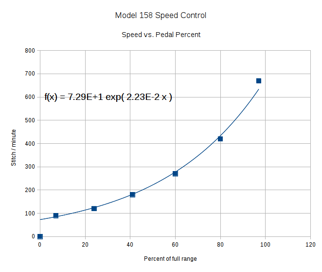
That sorta-kinda worked, but the user community said that the pedal response required pushing too hard for top speed: it should get faster, sooner. The problem came from the simplistic way I set the speed: it was inversely proportional to the position.
Plotting speed against pedal position shows the problem:
I figured the right approach was to make the speed vary linearly with the pedal position, so the trick was to plot the off-time delay vs. the actual speed:

The second-order equation bottles up a bunch of nonlinear things. Given that this was using the original code, I made the dubious assumption that more-or-less the same delay in the new code would produce more-or-less the same speed.
The new code discards the current-sampling routine that I was using to get a fixed delay (because I don’t need to know the current in pulse-drive mode), then used that time for the floating-point calculation required to find the off-time delay. That chunk of code took a bit of fiddling to get right:
case PD_RUN :
	if (PedalPosition > 5) {
		if (MotorDrive.State != RUNNING) {
			EnableMotor();
			MotorDrive.State = RUNNING;
		}

		BaseDAC.setVoltage(0x0fff,false);								// give it a solid pulse
		MillisOn = millis() + (unsigned long)DriveOnTime;

		TargetSpeed = (float)map(constrain(PedalPosition,0,PedalMaxClamp),
				0,100,
				0,700);						// quick and dirty 0 to 700 stitch/min range
		OffTime = (int)((1.94e-4*TargetSpeed - 0.286)*TargetSpeed + 106.0);
		OffTime = constrain(OffTime,0,120);								// clamp to reasonable range
		MillisOff = MillisOn + (unsigned long)OffTime;					// compute end of off time

		while (millis() <= MillisOn) {									// wait for end of pulse
			continue;
		}

		if ((PedalPosition >= 100) && (MotorDrive.SpeedRange == SPEED_HIGH)) {	// pedal down in full speed mode?
			printf("Full speed ... ");
			OffTime = 0;
			while (PedalPosition >= 100) {								//  ... full throttle!
				PedalPosition = PedalPercent(ReadAI(PIN_PEDAL));
			}
			BaseDAC.setVoltage(0,false);								//  pedal released, start coasting
			printf(" done\r\n");
		}
		else {															// pedal partially pressed
			BaseDAC.setVoltage(0,false);								// pulse done, turn motor off
			while (millis() <= MillisOff) {								// wait for end of off period
				continue;
			}
		}
	}
But the result looks as pretty as you could possibly expect:

The pedal still provides a soft-start transition from not moving to minimum speed, which remains an absolute requirement: having an abrupt transition to that straight line would be a Bad Thing. Fortunately, the nature of the magnet moving toward the Hall effect sensor gives you that for free.
Although we’re still evaluating the results, the user community seems happier…

