Ed Nisley's Blog: Shop notes, electronics, firmware, machinery, 3D printing, laser cuttery, and curiosities. Contents: 100% human thinking, 0% AI slop.
Category: Science
If you measure something often enough, it becomes science
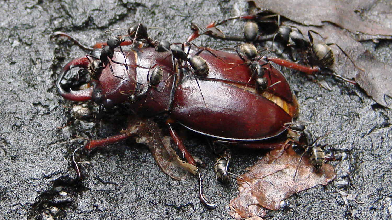
For all I know, the ants haul the carcass into position, blow the scuttling charges to loosen the armor, and sink it in a convenient spot on the driveway:
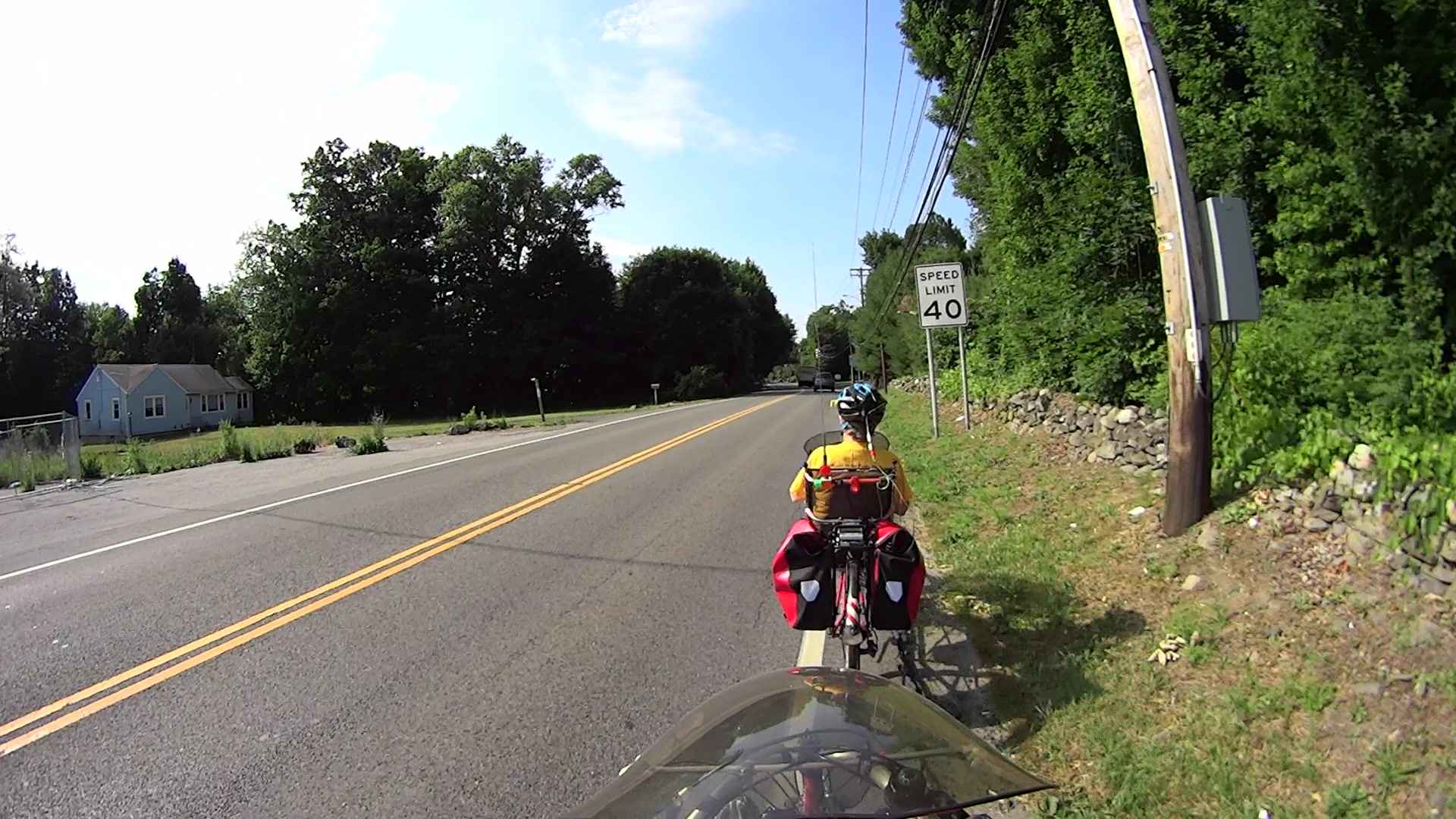
We often see Red Tailed Hawks circling high above the area, but this one came closer than most (clicky for more dots):
Red Tailed Hawk Red Oaks Mill 2016-06-27 – 0195
Surely you can see it, just to the left of the speed limit sign? It took us by surprise, too!
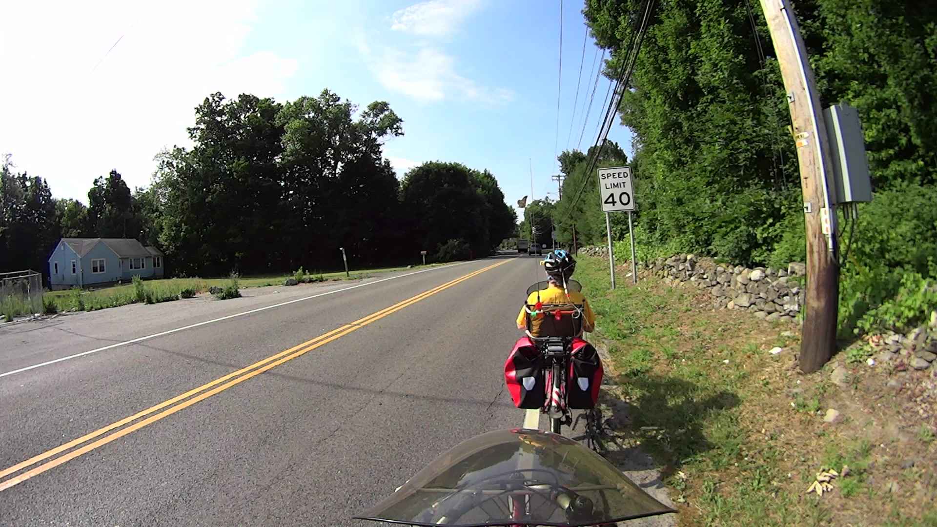
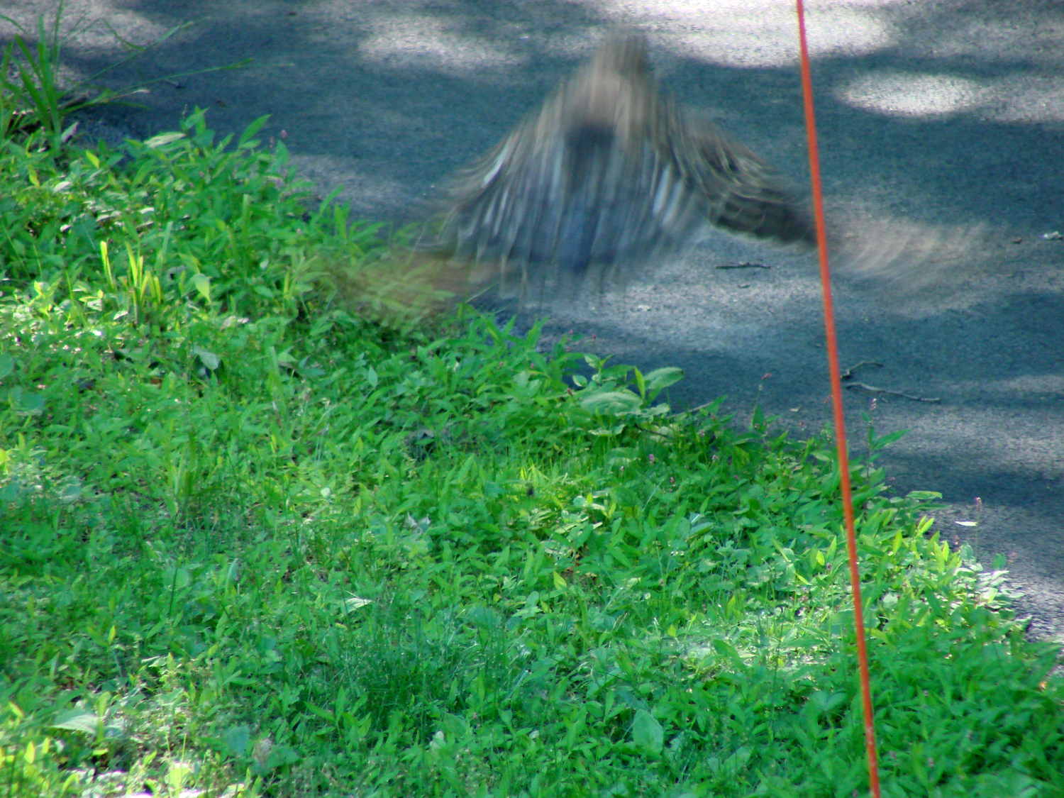
Near the middle of the road:
Red Tailed Hawk Red Oaks Mill 2016-06-27 – 0211
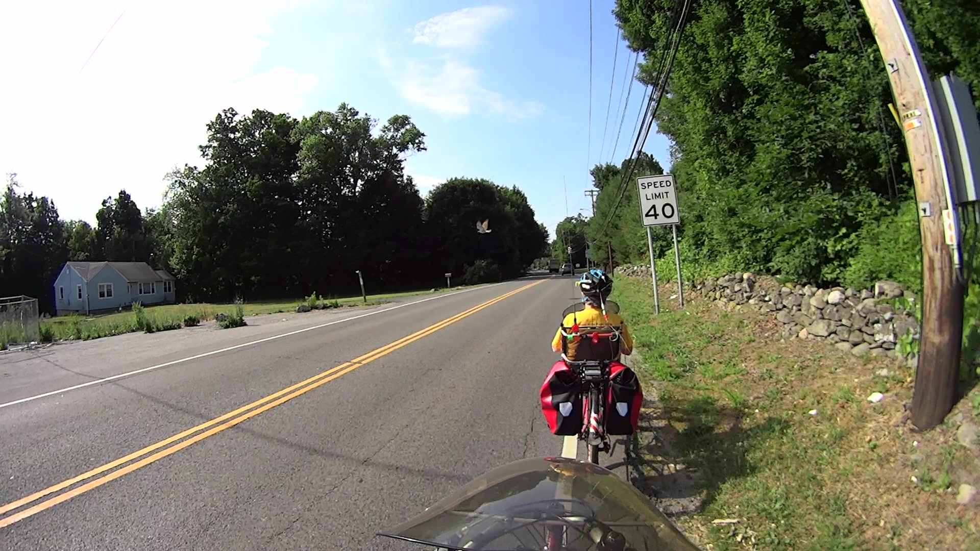
And away:
Red Tailed Hawk Red Oaks Mill 2016-06-27 – 0227
Perhaps it’s taking a break to enjoy just flying around? That’s about what we were doing; it was a fine morning for that sort of thing.
Squinting at a few more frames, it’s flying at 18 mph with 4 wingbeats per second. Not in a hurry, that’s for sure, and still traveling faster than we were.
We spotted a few Gas Hawks above the airport, too, but they stayed too far away for pictures…
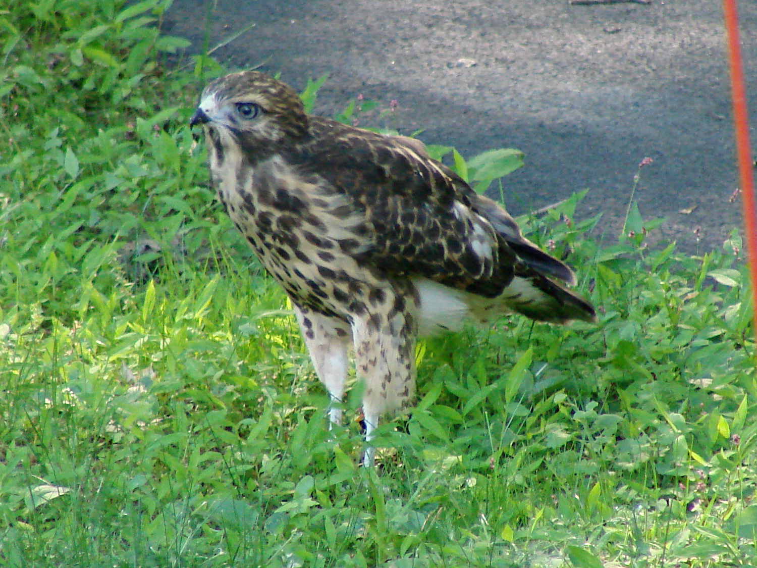
“Our” pair of Cooper’s Hawks (or their descendants, of which there have been many) hatched a pair of chicks that recently fledged and have been exploring their world:
New Hawks – standing tall
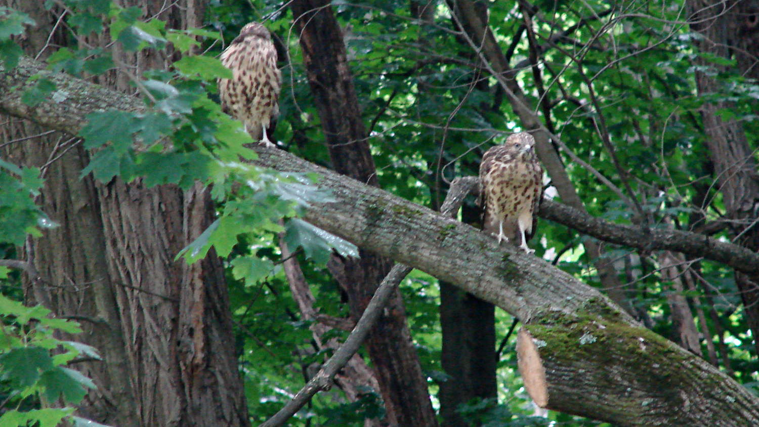
Sometimes they perch together:
New Hawks – companions
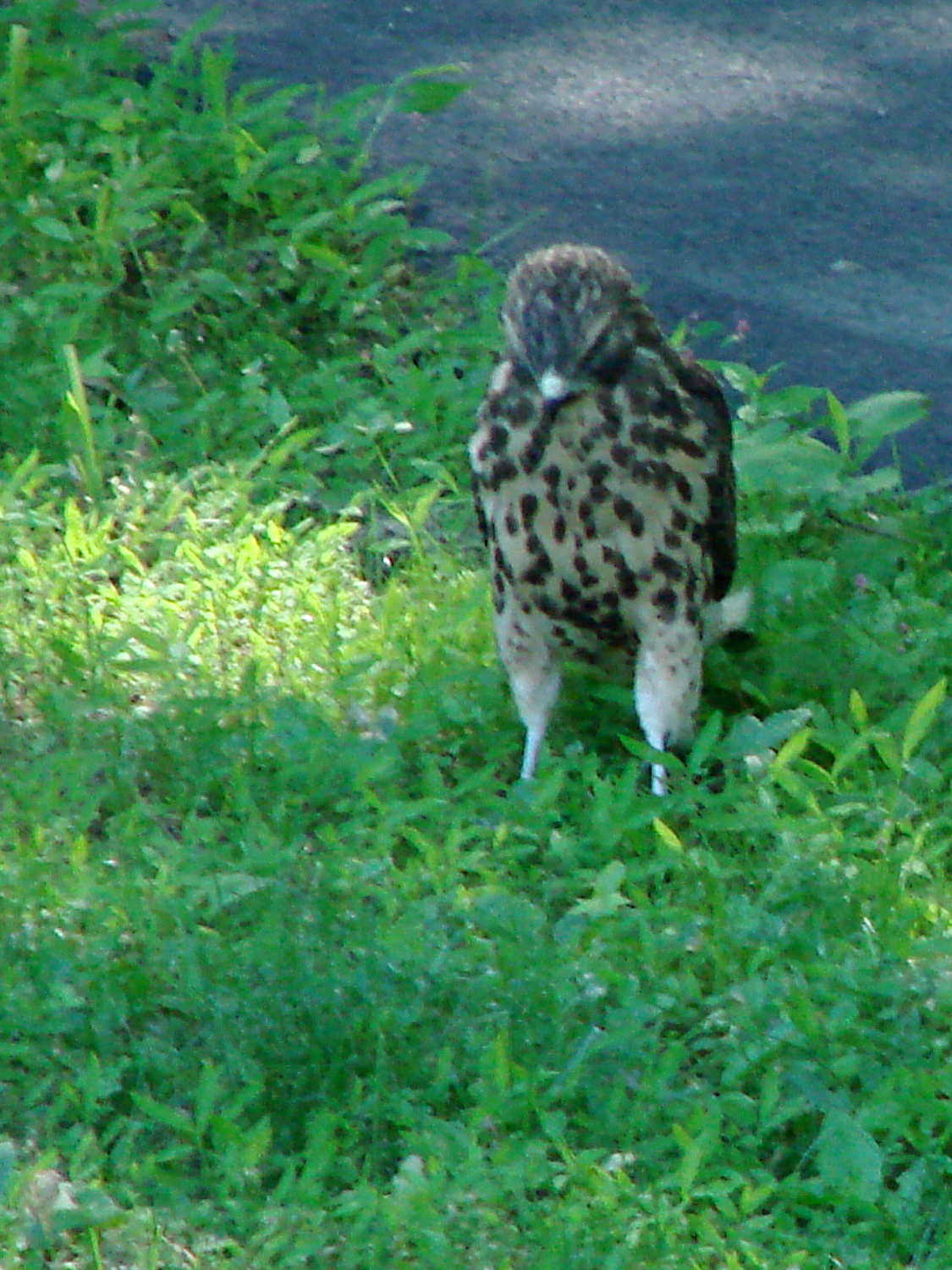
Their world contains many interesting things, not all of which are visible to the human eye:
New Hawks – curiosity
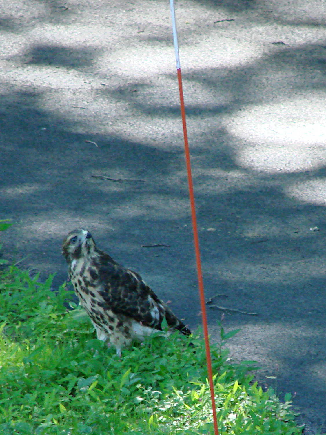
I’ve spotted a parent hawk circling high overhead while the youngsters practice their flight skills near the treetops. If you listen carefully, you can hear a hawk calling from far above:
New Hawks – parent overhead
We’ve seen them hopping from branch to branch, testing their wings, and by now they can launch from a standing start:
New Hawks – liftoff
New squirrels emerge at about the same time, with equivalent levels of experience:
New Hawks – curious squirrel
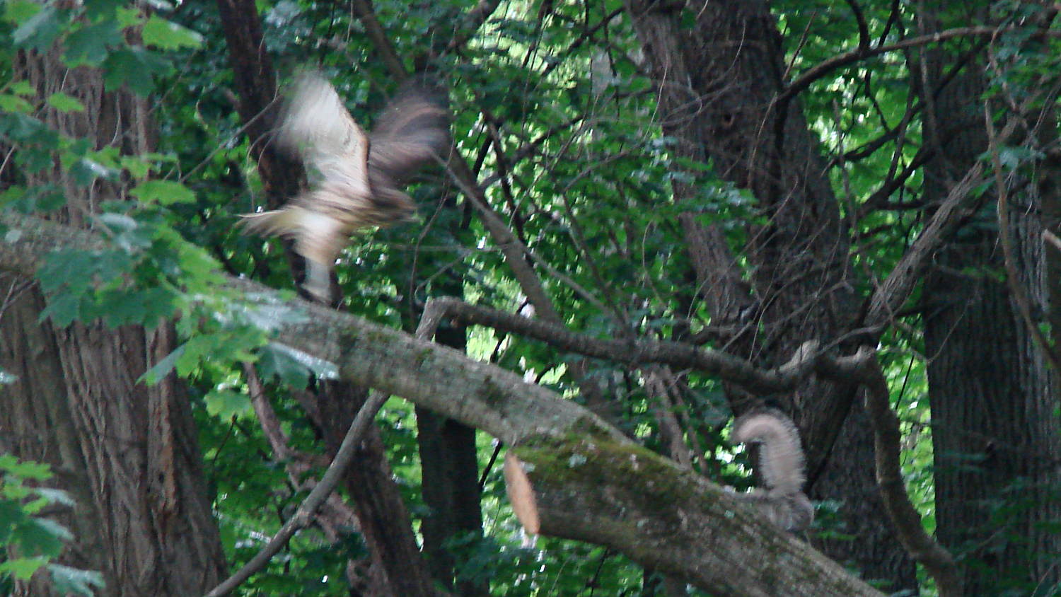
Right out of the nest, new hawks know what to do, if not quite how to accomplish it:
New Hawks – vs New Squirrel
That little squirrel instantly pasted itself to the bottom of the branch and escaped. This time, anyway.
Mary watched one hawk practicing its pouncing skills by attacking a pine cone. A talon wedged under a tight pine cone scale, to the extent that the hawk spent the next half hour flopping around the yard trying to part company with its personal Pine Tar Baby.
Perhaps the piles of Chipmunk Gibbage came from a new hawk practicing its regurgitation skills …
Go, new hawks, go!
Taken with the Sony DSC-H5, sometimes with the 1.7x teleadapter, under ambient light, hand-held, sometimes braced against the frame of a partially open door.
Yeah, tanker boots and all; not the weirdest thing we saw during RIT’s graduation ceremonies.
This summer marks her fourth of four co-op semesters with Real Companies Doing Tech Stuff and her final classes end in December; RIT holds one ceremony in the spring and being offset by a semester apparently isn’t all that unusual. She (thinks she) has a job lined up after graduation and doesn’t need her doting father’s help.
But, hey, should you know someone with a way-cool opportunity (*) for a bright, fresh techie who’s increasingly able to build electronic & mechanical gadgets and make them work, drop me a note and I’ll put the two of you in touch. [grin]
(*) If that opportunity should involve 3D printed prosthetics with sensors and motors, she will crawl right out of your monitor…
With a new motor and controller in the reconfigured SqWr Power Wheels chassis, I made a few measurements under somewhat less than controlled conditions, with the butt end of the chassis on jack stands. The general idea was to find out what the “lightly loaded” condition looked like in terms of motor current; after some mechanical and electrical improvements, we’ll be in a better position to determine the battery load & suchlike.
Preliminary measurements:
Motor DC resistance: 0.7 Ω (meter lead resistance 0.2 Ω, so don’t trust it)
Motor winding inductance: 128 µH
Motor shaft key: 1/8 inch (keyway chewed by pulley setscrews, needs matching shaft flats)
Twist-grip throttle applies nonzero voltage when released: possibly damaged
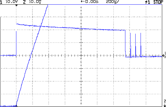
With everything in position and the Tek 6303 probe set for 10 A/div, this is what happens when you push the deadman switch:
Out V I 10 A – start transient
Obviously, the motor controller takes much too long to wake up & sense the current.
The initial slope of that current waveform looks like 80 A/360 µs = 220 kA/s. The upper trace gives the motor voltage, so 23 V / (220 kA/s) = 104 µH, surprisingly close to the measured 128 µH.
Deploying the mighty Tek CT-5 (with an enclosed A6302), cranking the gain to 50 A/div, and poking the deadman again:
Out V I 50 A – start transient full
During that initial pulse, the controller connects the battery directly to the motor, so you’re looking directly at 200 A of battery current. For reasons that aren’t relevant here, the mandatory 60 A safety fuse isn’t present, although it should be able to withstand a millisecond or two of moderate overload without blowing.
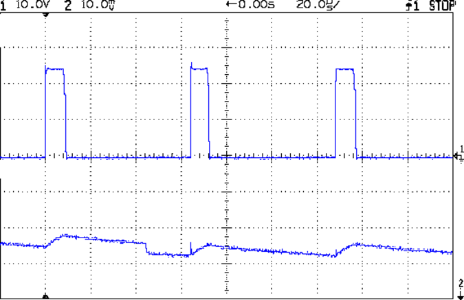
With that out of the way and the motor running at a few hundred RPM, due to the nonzero twist-grip output voltage with no throttle applied, the controller actually does PWM pretty much as you’d expect:
Out V I 10 A – run low speed
It’s not clear what caused the small dent just before the middle pulse; perhaps the motor commutator switched from one winding to the next.
The battery current will be much lower than the motor current in this mode, roughly (motor current) * (PWM fraction). We haven’t verified that, but for 30% PWM it should be around 5 A = 15 A * 0.30. The actual battery current looks smoother than I expected, although I have no traces to show for it; more study is needed.
Eks once again graciously loaned me his Tek current probes; this whole Power Wheels mess motivated me to get off my ass and accumulate my own collection, about which more later.
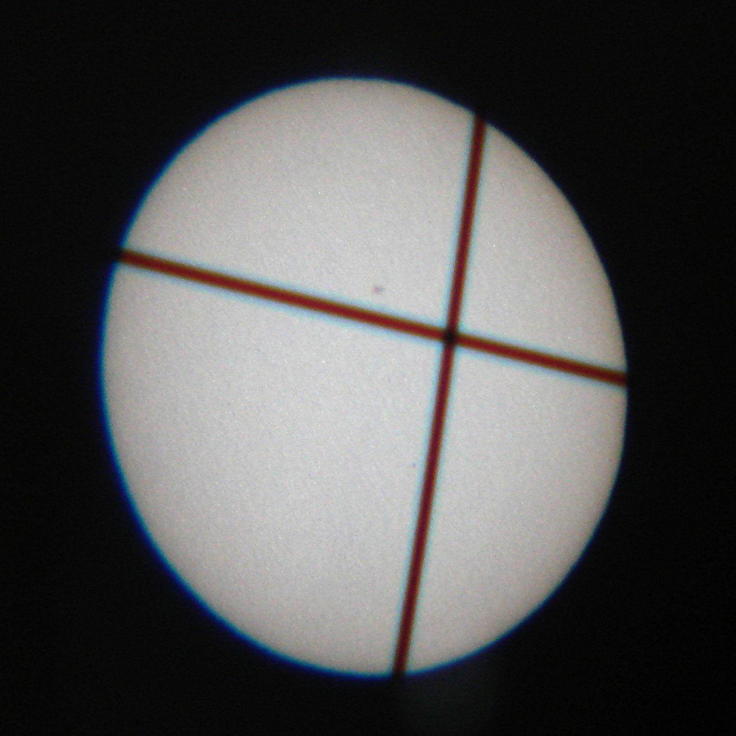
If you know what you’re doing, you can measure the size of the sun and scale the entire solar system from observations like that. Takes more science than I’ll ever accomplish, that’s for sure!
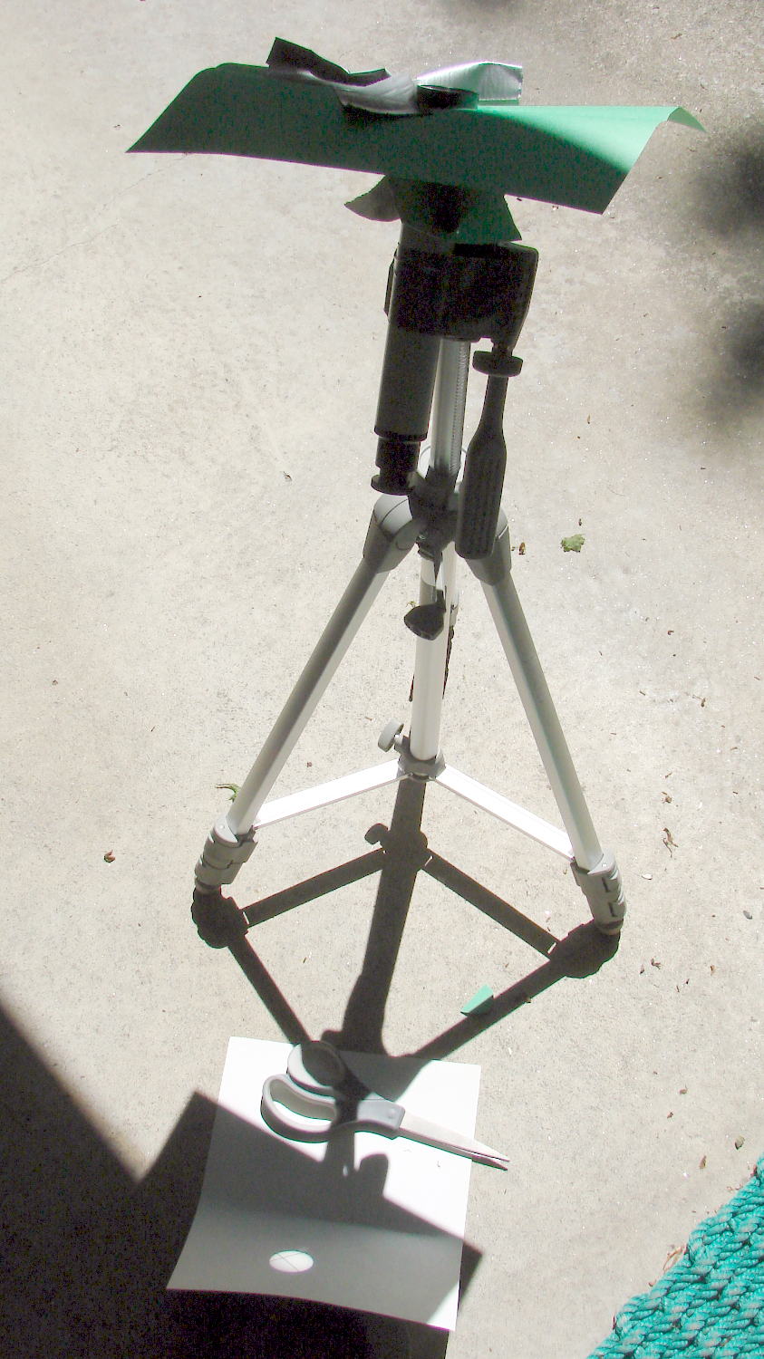
I realized the show was on just before Greatest Transit (roughly what you see above), so I duct-taped a 1 inch spotter / finder scope to a camera tripod, taped a sun shield on the scope, bent some card stock for a screen, then assembled everything on the patio:
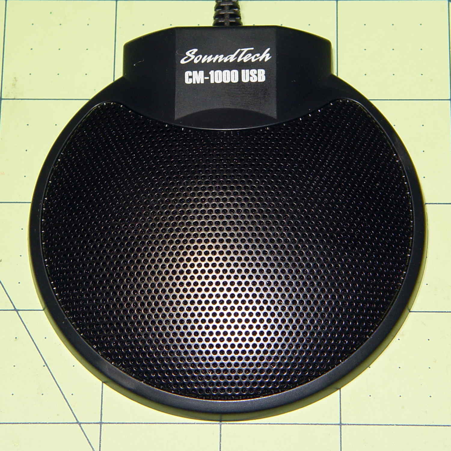
Although microphones intended for conference tables aren’t suitable for inconspicuous hearing aids, they go a long way toward working out algorithms (*). This is a SoundTech CM-1000 USB mic:
SoundTech CM-1000USB microphone
It produces noise-canceled stereo output and a quick test shows impulse sounds produce reasonable left and right responses responses; I can’t vouch for the noise cancelling part.
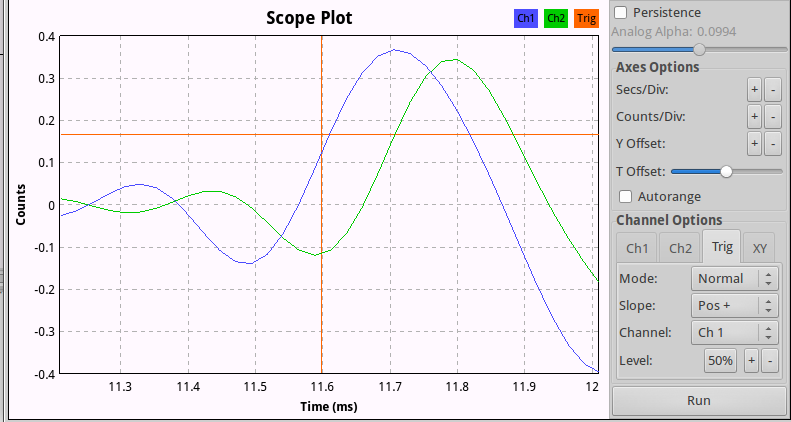
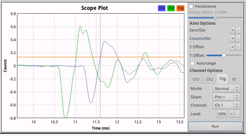
A click to the right side:
CM-1000USB mic – Right pulse
And to the left:
CM-1000USB mic – Left pulse
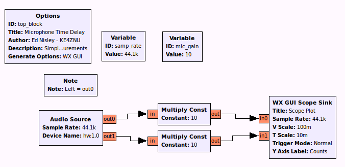
The green trace (Channel 2) is obviously the Right channel, which corresponds to in1 on the Scope Sink block and out1 of the Audio Source in the GNU Radio data flow diagram:
Microphone Time Delay.grc
There’s an irreconciliable clash between 0-index and 1-index numbering in there, but the microphone’s “Left” and “Right” channels appear in the proper places when you look at the mic from the conference room side of the label as shown in the top photo.
Figuring the speed of sound at 344 m/s, that 100 µs delay means the mic capsules sit 34 mm apart, which looks to be about right, as the flat part of the housing under the label spans 22 mm.
That’s a tad skimpy for things like beamforming and direction finding, so I actually bought a set with a separate CM-1000 mic that plugs into the USB mic:
SoundTech CM-1000USB and CM-1000 microphones
The channel layout diagram explains what’s supposed to happen:
Soundtouch CM-1000USB microphone channel layout
The additional mic changes the response, so that the USB unit becomes the Left channel and the analog mic provides the Right channel. I don’t know what happens to the “noise canceling” part of the story.
With the mics positioned 200 mm on center, a click to the right side:
SoundTech CM-1000 mics – 200 mm OC – Right pulse
The eyeballometrically precise 600 µs delay corresponds to 206 mm at 344 m/s, which might actually be close: they’re 200 mm on center, but the Right-channel mic is 10 mm smaller and the mic might be half that much further away from the other one. Not that that makes any difference.
(*) And, frankly, slapping a mic on the table won’t bother me much at all…