A long long time ago, we bought a kitchen spatula that’s served us well ever since:
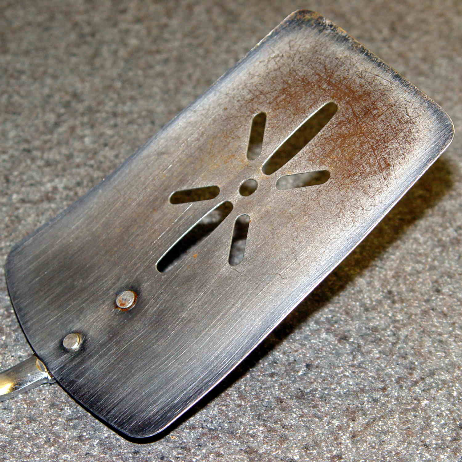
To give you an idea of how old that poor thing is, the back of the handle bears a Japan stamp. I’ve re-set the rivets several times, the blade has rusted as badly as you think, and we recently, very reluctantly, decided it has passed its best-used-by date.
The 3 x 4.5 inch blade is 19 mil = 0.45 mm plated carbon steel, stiff enough to remain flat and springy enough to bend a little, with a 9 inch = 230 mm steel handle ending in a plastic overmold.
These days, it’s essential to the cutting, flipping, and serving of the morning’s omelet-like substance, made of eggs, bacon, veggies, green leafy things, plus this-and-that, in the cast-iron pan. Mary chops the disk into quarters with the reasonably sharp edge, maneuvers the reasonably bendy blade under each quarter, flips them over, tops with bacon & cheese, pauses for consolidation & melting, then pops them onto plates. Yum!

So we set out to buy a replacement.
Here’s what we’ve tried and rejected so far:
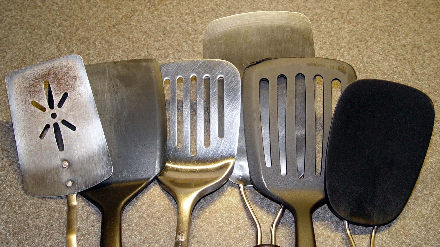
I’ve used this one for many years to flip pancakes on a succession of non-stick griddles, a service at which it excels. The edge isn’t sharp enough to cut the green-and-leafy and the completely inflexible blade cannot be maneuvered under the omelet quarters:

This one gets deployed for burgers and their ilk, also in the cast-iron pan. The blade, although sharp enough, is completely rigid:

On the other paw, a slightly concave 7 mil = 0.18 mm spring steel blade is much too thin and, well, springy. Although very sharp, you cannot apply enough cutting force without suddenly bending the blade and, if the omelet quarter isn’t positioned exactly right, the blade will bend underneath it and dump breakfast on the stovetop. The alert reader will notice a missing weld between the blade and the bottom wire handle:

This very thin plastic blade has similar problems with poor cut-ability and excessive flexibility:
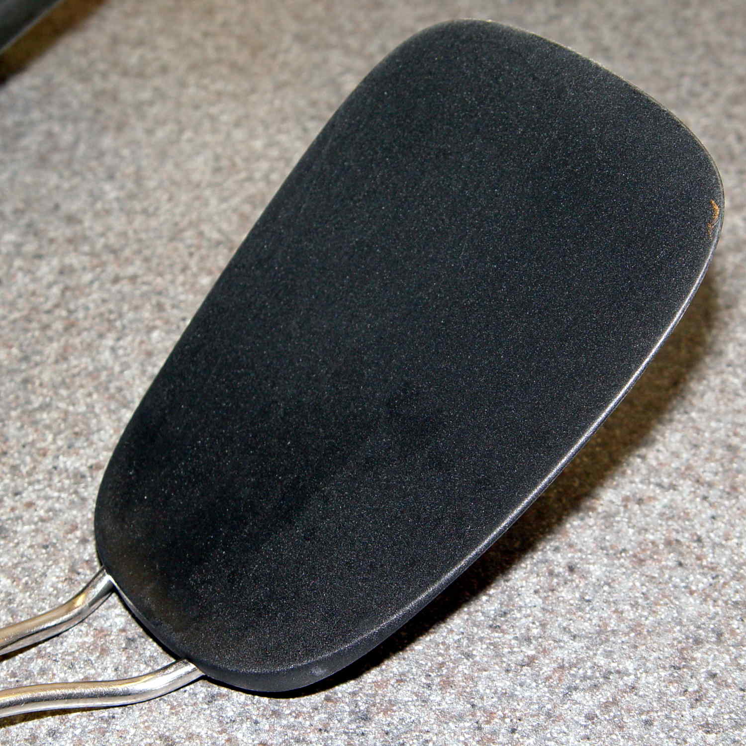
This one looked really promising and worked almost perfectly. Regrettably, its nylon blade bears a 400 °F rating and the bottom of the omelet reaches nearly 450 °F. You can see what happens to the reasonably sharp edge as it scrapes across the pan:

The omelet cooks at the temperature it cooks at, which part of the specifications is not subject to further discussion.
So, we’re stumped. Having trawled the usual online and big-box stores, we’ve been unable to find a replacement. Simple steel blades aren’t available. Trendy silicone-bonded stainless steel blades combine the worst of all worlds: won’t cut and won’t flip. Pretty nearly anything you don’t see above seems obviously unsuitable for our simple needs: too big, too small, or too melty.
We’ll consider all recommendations and suggestions! Thanks …