Ed Nisley's Blog: Shop notes, electronics, firmware, machinery, 3D printing, laser cuttery, and curiosities. Contents: 100% human thinking, 0% AI slop.
Category: Science
If you measure something often enough, it becomes science
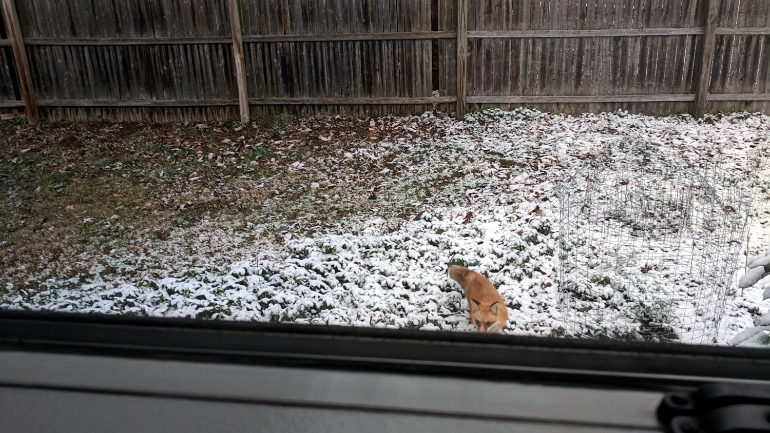
A Red Fox came trotting around the garden on the day before Christmas, then nosed up to the back of the house:
Red Fox visitation – 2018-12-24
Presumably, it was in search of a snack. We wish it good hunting.
A few hours later, the fox walked quickly across the back yard with half a dozen turkey toms close behind, perhaps urging it away from their hens. Everybody remained calm and collected, knowing their roles in this particular play.
FWIW, Marist College fields Red Foxes athletic teams. The women’s teams are Lady Red Foxes, as “vixen” carries entirely inappropriate connotations.
Building an astable multivibrator from MOSFETs for longer time constants and more reliable operation suggests I should know a bit more about their operation with minuscule currents and low voltages. I have a small stock of low-threshold ZVNL110A MOSFETs, but using something less obsolete seems in order.
Dirt-cheap 2N7000 MOSFETs have a maximum IDSS around 1 µA at room temperature, which would be way too high in this situation; there wouldn’t be much difference between their ON and OFF states.
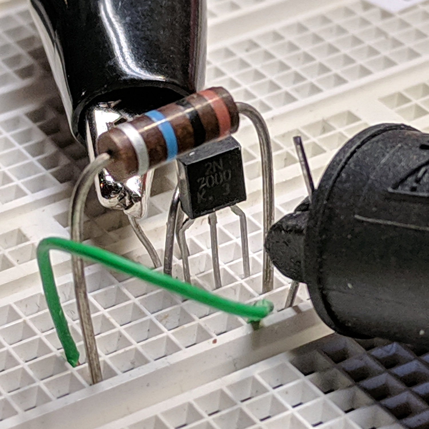
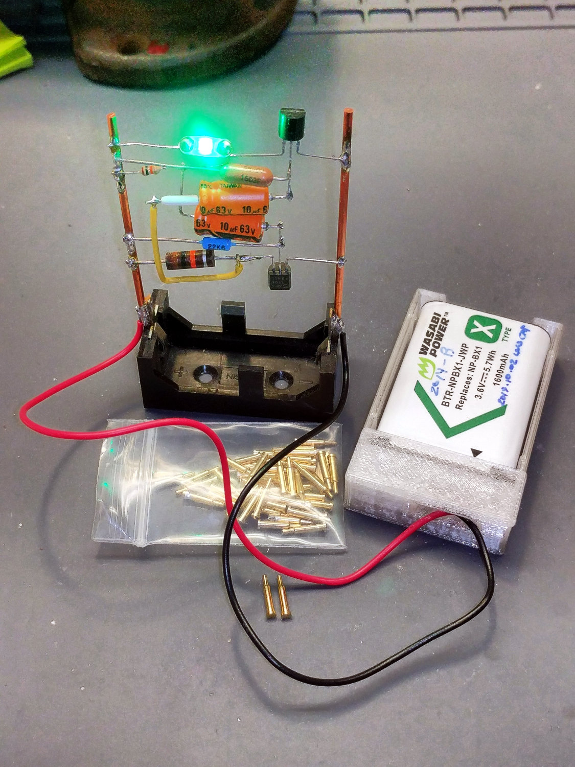
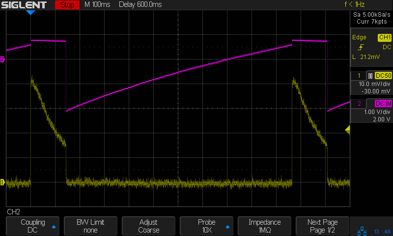
The test setup is simplicity itself:
2N7000 IDSS – calibration
The initial reading from a 4 V bench supply was 0.00 µA on the Siglent SDM3045, my best low-current meter, so I put a 10 MΩ resistor across the drain and source terminals:
Astable – 2N7000 – IDSS cal
Close enough, particularly given the silver fourth band on that old carbon composition resistor and its no-doubt unclean surface.
The rest of the 2N7000 MOSFETs have IDSS ≤ 10 nA, which you can’t distinguish from zero on that scale.
The 2N7000 datasheet specs give a threshold voltage from 0.8 to 2.5 V for 1 mA drain current, bracketing a 2.1 V typical value, which would be too high for a nearly dead lithium cell.
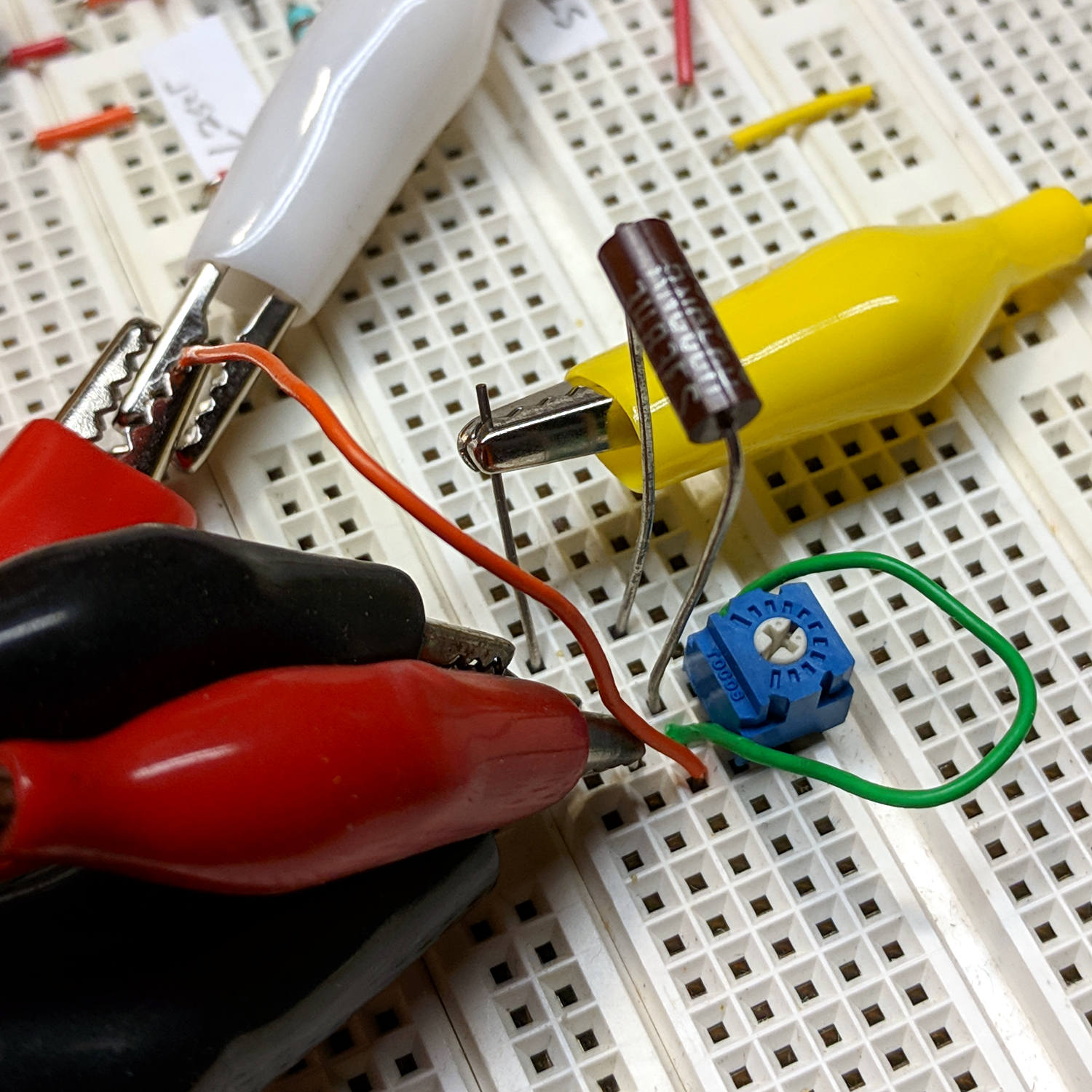
I calibrated the VGS(thr) current at 11 µA with a 348 kΩ resistor:
2N7000 MOSFET Id cal
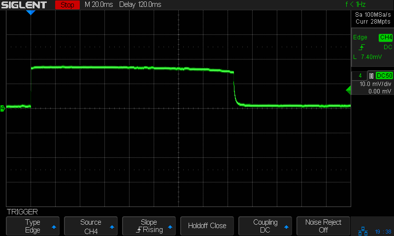
Which produced 11.49 µA at 4 V, just as it should, so I plugged in a MOSFET and twiddled the trimpot for a nice round 10 µA:
2N7000 MOSFET Vthr test
Most transistors conducted 10 µA with the gate at 1.42 V, with a few outliers spanning 50 mV on either side. Close enough and low enough!.
At this late date, the RepRap site has a much better G-Code reference, at least for the weird and wonderful assortment of 3D printer commands.
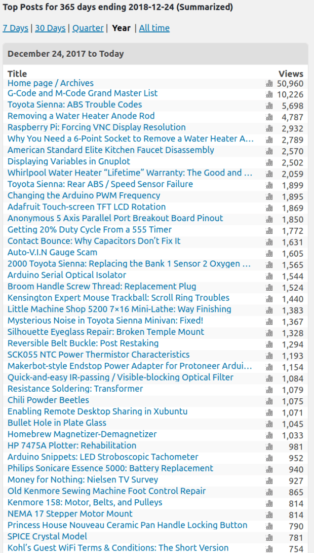
Given that I’m at best a secondary reference for Toyota Sienna ABS trouble codes, things must be getting grim out there in the minivan crowd.
And, as always, houses (and especially plumbing) are trouble!
As for everything else, well, it’s just me and my shop notes …
WordPress reports 101 k ad impressions per month for 24.6 k “page views”, suggesting most folks see four ads per page. If you’re not using an ad blocker, start now!
Those seem to be the most aggressive (and thus highly desirable to advertisers) video ads, because WordPress pays me a whopping 8¢ per kilo-impression; a few percent of the Youtube rate. The numbers are dropping, though, suggesting ads will never push me into the ranks of the thousandaires.
Down near the end, the poor thing barely gave one brushing after an overnight charge.
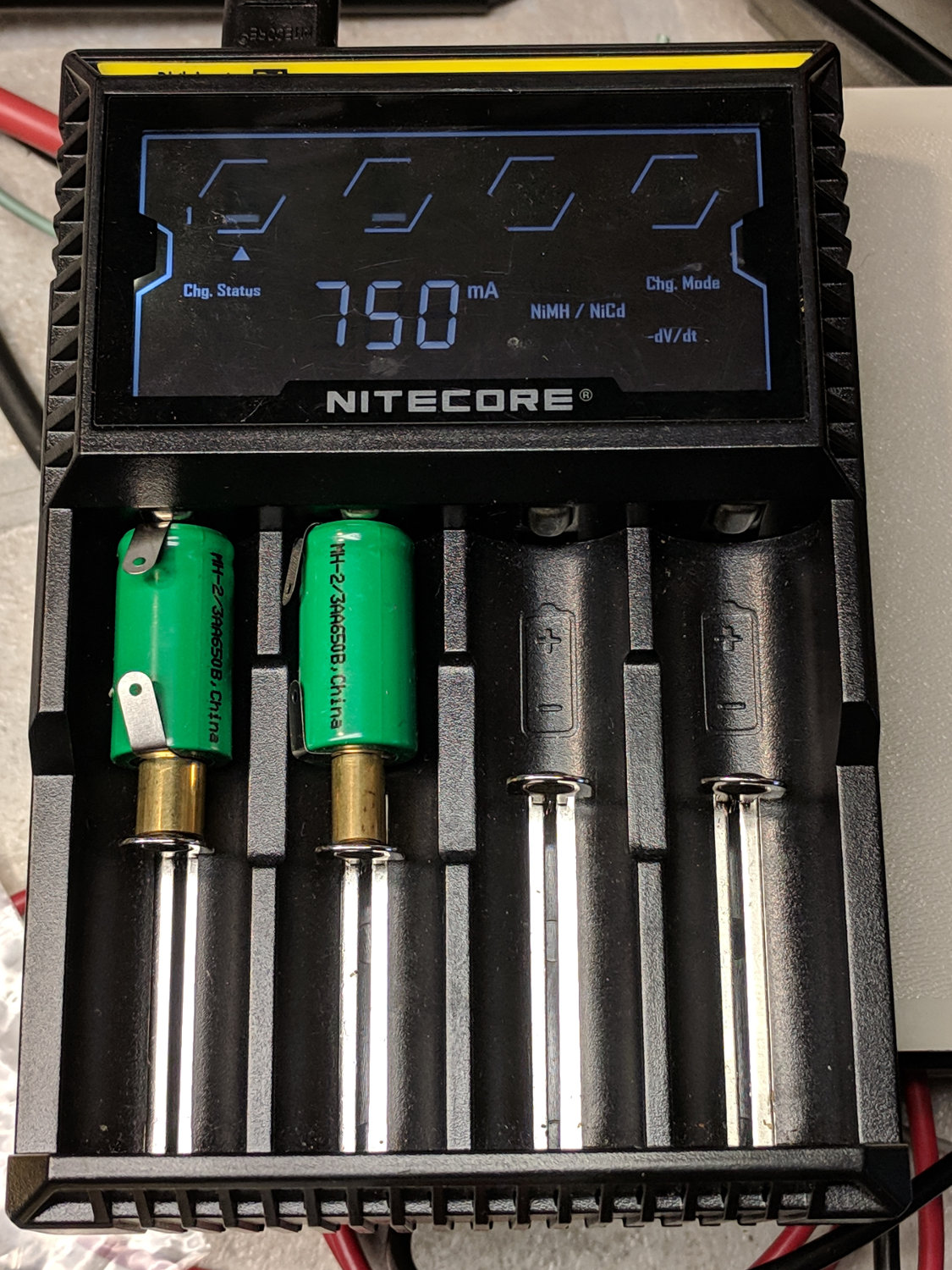
While I was dismantling the case, I charged the last two new-old-stock NiMH cells:
Sonicare Essence – charging short cells
They arrived the same five years ago as the deaders in the toothbrush, but haven’t been used in the interim and charged well enough. The NiteCore D4 charger arrived after they did and isn’t really intended for 2/3 AA cells, so I used short brass tubes to make up the difference. I should have used the 300 mA low-current charging option (press-and-hold the Mode button for a second), although it didn’t overcook them at 750 mA.
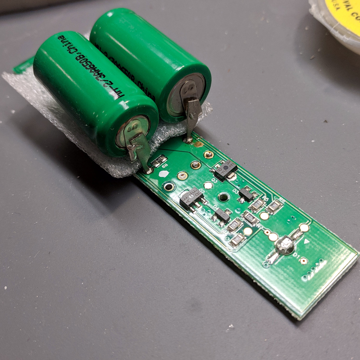
The process went pretty much as before, with the new cells soldered in place atop the PCB:
Sonicare Essence – batteries on PCB
And the PCB tucked back into the case:
Sonicare Essence – batteries installed
I applied a solder bridge to the BLINKY pads, which seemed to disable the blinking and turn the LED on full with the toothbrush in the charger. Without waiting for a full charge cycle, I sucked the solder off the pads and restored the previous blinkiness.
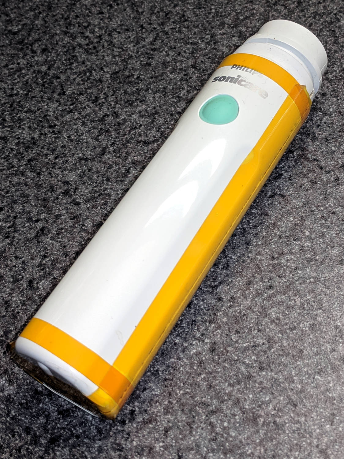
A few strips of Kapton tape and it’s back in operation:
Sonicare Essence – retaped
The first charge lasted for two weeks, so things are looking good again. When the stock of knockoff replacement brush heads wears out, it’ll be time to get a whole new toothbrush … even if the batteries aren’t completely dead yet.
A House Finch suffering from Finch Eye Disease prompted me to sterilize our feeder, which meant providing a temporary feeder to keep the birds flying. Having an abundance of lids from six gallon plastic cans / buckets, this made sense:
Can Lid Feeder – installed
Which required an adapter betwixt pole and lid:
Can Lid Feeder – assembled
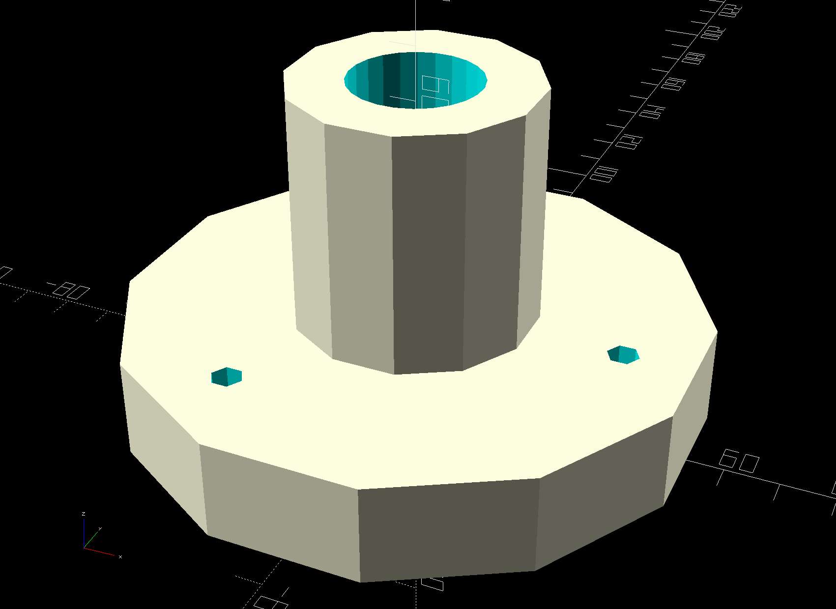
Which requires a bit of solid modeling:
Can Lid Platform Feeder Mount – solid model – bottom
The lids have a central boss, presumably for stiffening, so the model includes a suitable recess:
Can Lid Platform Feeder Mount – solid model – support structure
As usual, automatically generated support fills the entire recess, so I designed a minimal support structure into the model and cracked it out with very little effort:
Can Lid Feeder – support structure
The tangle off to the right comes from a bridge layer with a hole in the middle, which never works well even with support:
Can Lid Platform Feeder Mount – Slic3r – bridge layer
Didn’t bother the birds in the least, though, so it’s all good.
This file contains hidden or bidirectional Unicode text that may be interpreted or compiled differently than what appears below. To review, open the file in an editor that reveals hidden Unicode characters.
Learn more about bidirectional Unicode characters
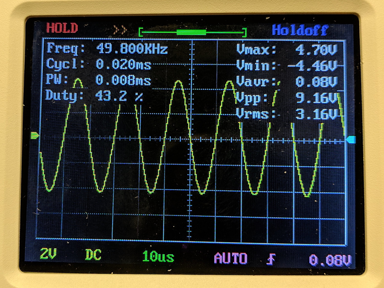
The DSO150 oscilloscope’s specs give a 200 kHz bandwidth, so a 50 kHz sine wave looks pretty good:
DSO150 – sine wave 50 kHz 10 us-div
A 100 kHz sine wave looks chunky, with maybe 25 samples per cycle:
DSO150 – sine wave 100 kHz 10 us-div
The DSO150 tops out at 10 µs/div, so you can’t expand the waveform more than you see; 25 samples in 10 µs seems to be 2.5 Msample/s, exceeding the nominal 1 Msample/s spec. I have no explanation.
A 10 kHz square wave shows a blip just before each transition that isn’t on the actual signal:
DSO150 – square wave 10 kHz 20 us-div
At 50 kHz, there’s not much square left in the wave:
DSO150 – square wave 50 kHz 10 us-div
And, just for completeness, a 200 kHz square wave completely loses its starch:
DSO150 – square wave 200 kHz 10 us-div
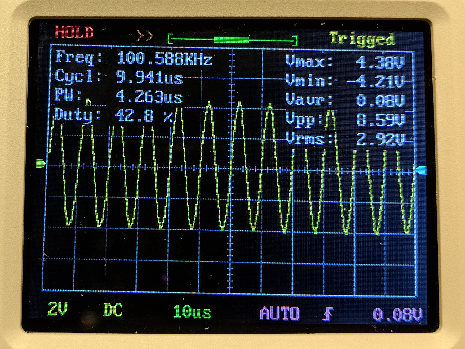
A 10% (-ish) duty cycle pulse at 25 kHz has frequency components well beyond the scope’s limits, so it’s more of a blip than a pulse:
DSO150 – pulse 25 kHz 10 us-div
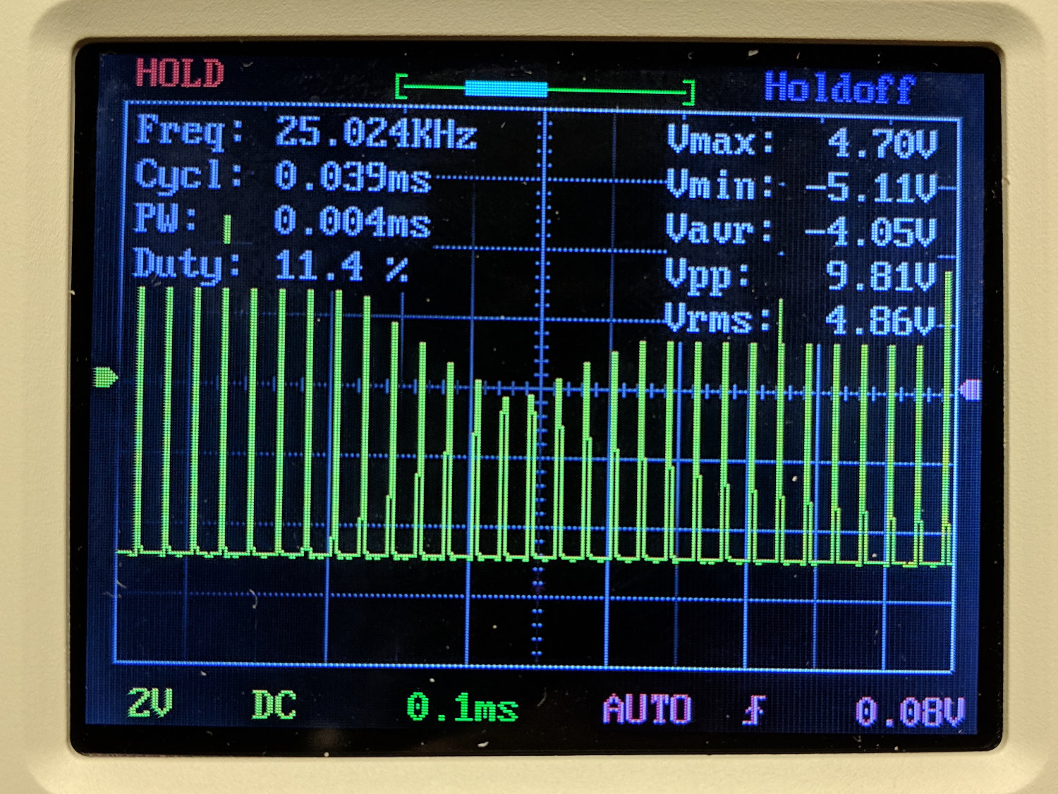
The pulse repetition frequency beats with the scope sampling and sweep speeds to produce weird effects:
DSO150 – pulse 25 kHz 100 us-div
Tuning the pulse frequency for maximum weirdness:
DSO150 – pulse 15 kHz 200 us-div
None of this is unique to the DSO150, of course, as all digital scopes (heck, all sampled-data systems) have the same issues. The DSO150’s slow sampling rate just makes them more obvious at lower frequencies.
Key takeaway: use the DSO150 for analog signals in the audio range, up through maybe 50 kHz, and it’ll produce reasonable results.
Using it for digital signals, even at audio frequencies, isn’t appropriate, because the DSO150’s low bandwidth will produce baffling displays.