Ed Nisley's Blog: Shop notes, electronics, firmware, machinery, 3D printing, laser cuttery, and curiosities. Contents: 100% human thinking, 0% AI slop.
Category: Science
If you measure something often enough, it becomes science
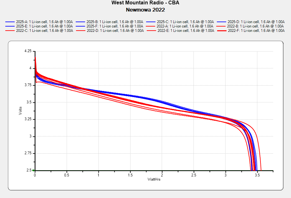
I don’t know what the bump in the middle of the new battery discharge curve means. Something weird in the chemistry, I suppose. Getting good batteries from Amazon surely remains a crapshoot and I now have four chargers.
Recharging all six batteries required 5488 mA·hr, just over 900 mA·hr apiece. Running the camera on a one-hour bike ride burns 600-ish mA·hr, so that’s comforting.
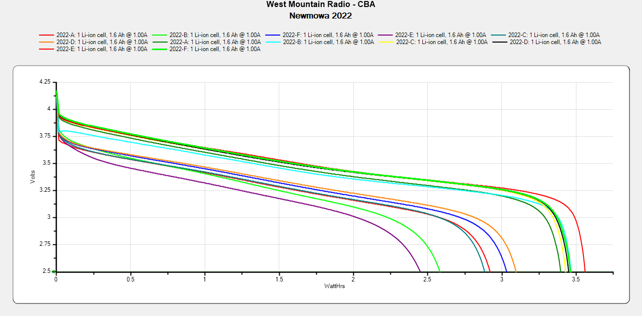
Comparing the new results with the 2022 batteries tested last month:
NP-BX1 – Newmowa 2022 in 2025-06
The upper traces appear in red in the first plot, the lower curves come from three years of use.
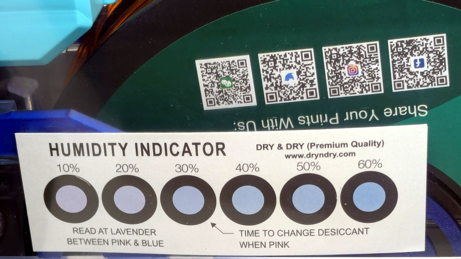
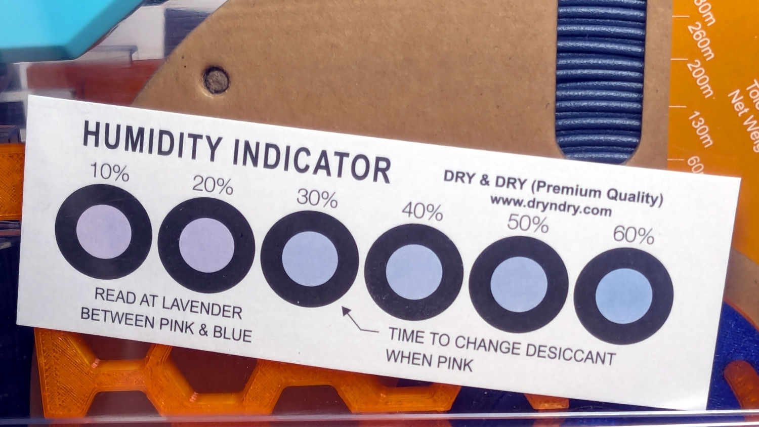
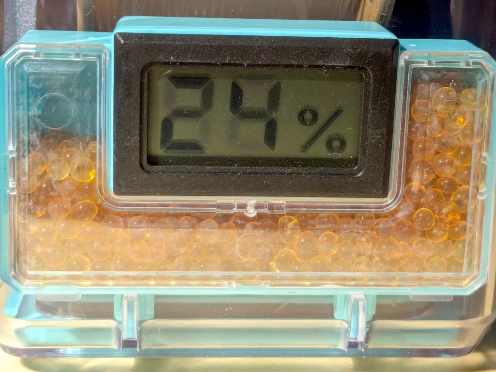
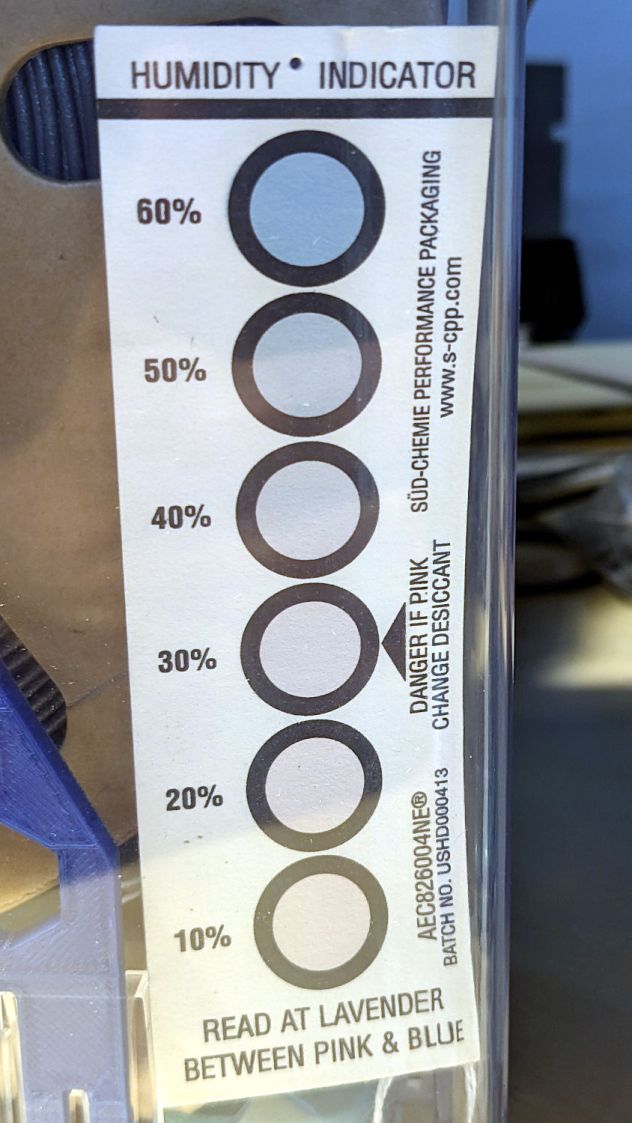
A week after installing 25 g of fresh silica gel, without any outside influence other than using some of the filaments to build things, I recorded the humidity meter reading, the indicator card colors, and the weight gain.
Click on any picture for more dots and to get rid of the captions and their stylin’ photo-blur.
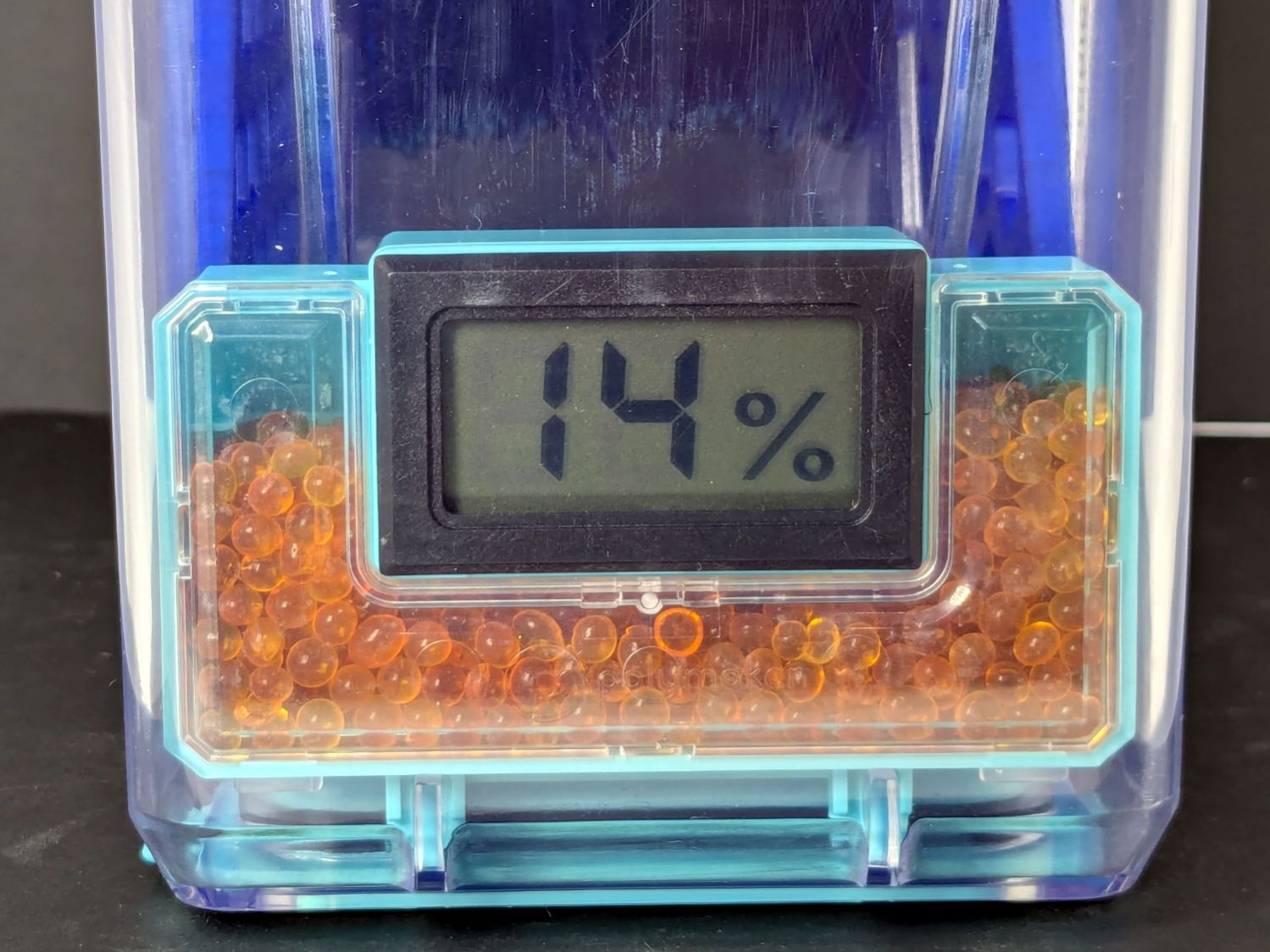
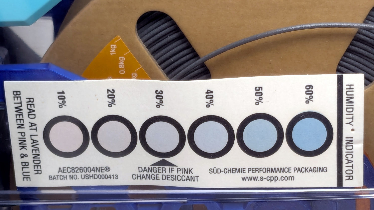
White PETG, gain 0.6 g:
Polydryer – 14 pctRH – meter – white PETGPolydryer – 14 pctRH – card – white PETG
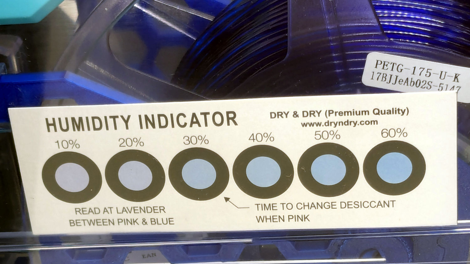
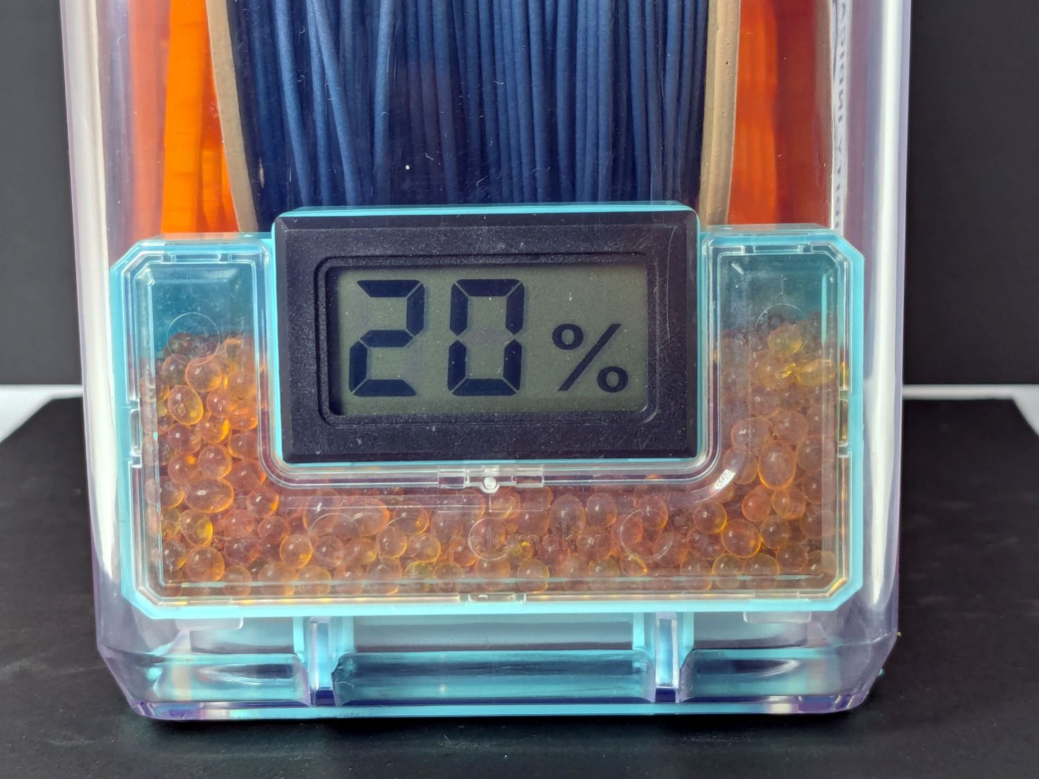
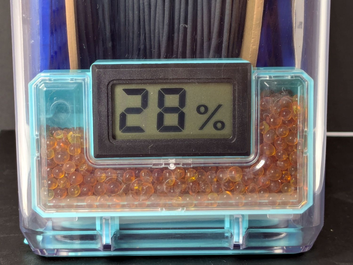
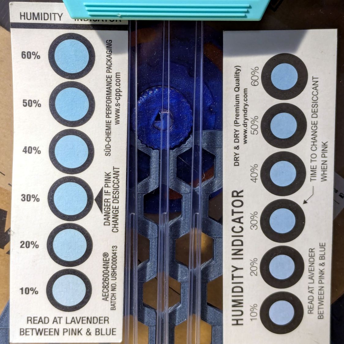
Black PETG, gain 0.8 g:
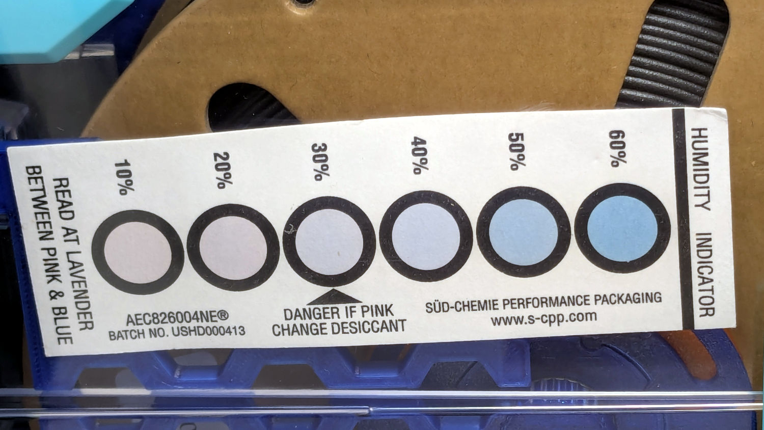
Polydryer – 21 pctRH – meter – black PETGPolydryer – 21 pctRH – card – black PETG
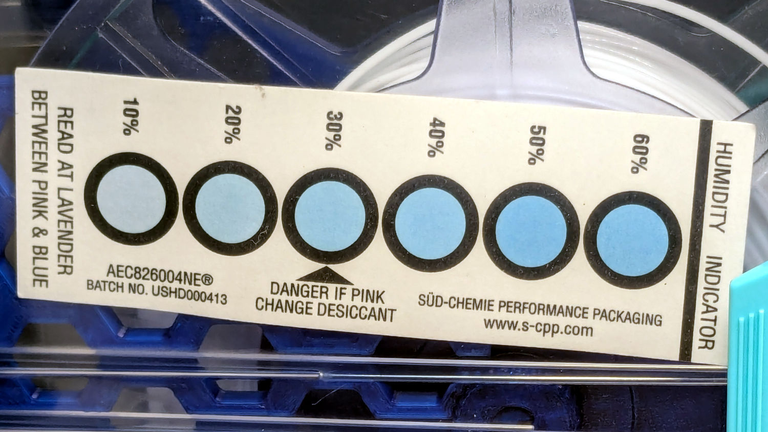
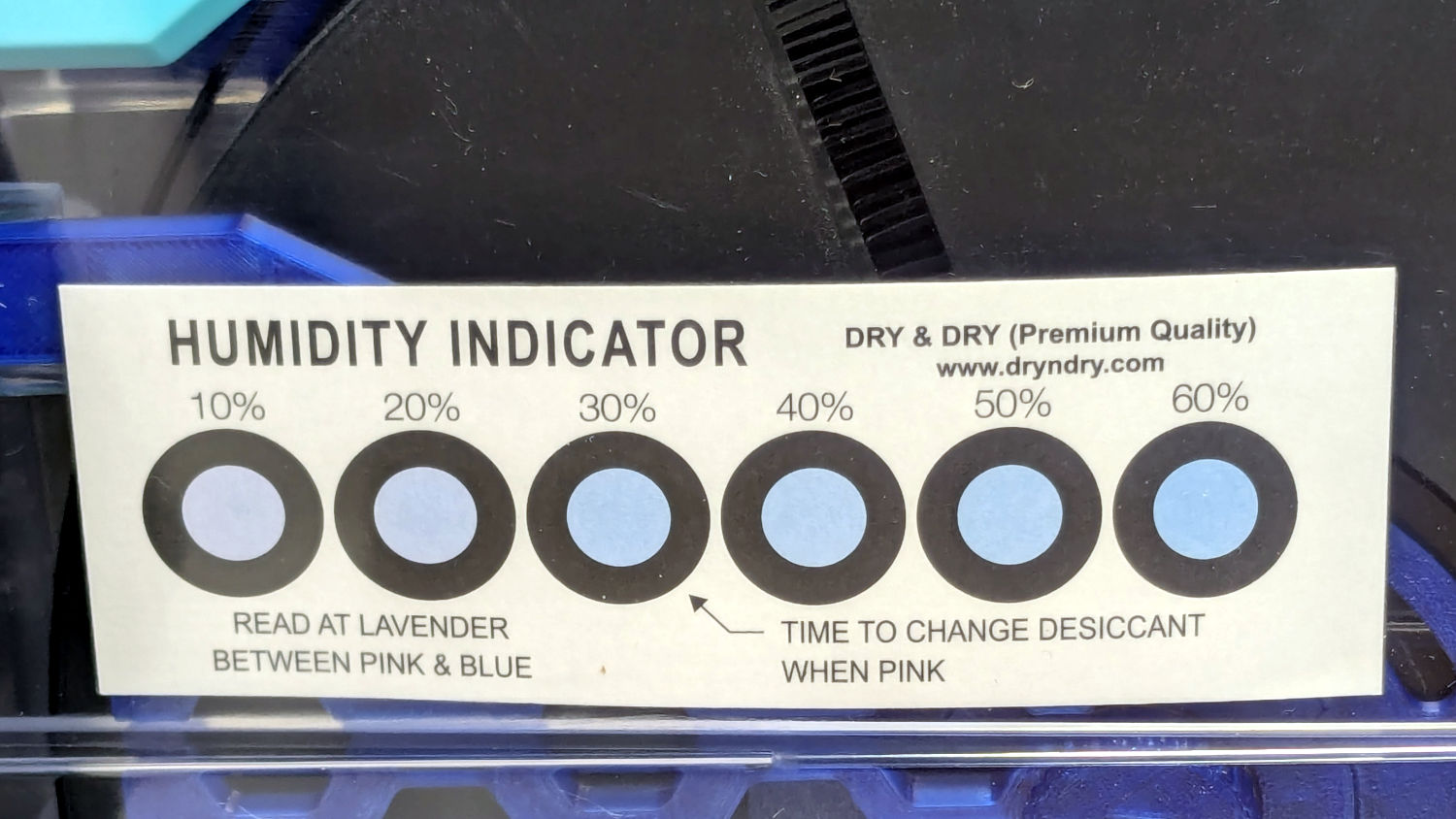
The (newer) indicator cards with the smaller dots / larger black borders seem less acute than the (older) large-dot cards. The two 28 %RH cards look about right, but the 20 and 21 %RH cards seem more different than the similar humidity would suggest.
Under 20 %RH, all the spots look pretty much the same, but AFAICT any humidity below 20 %RH is Good Enough for 3D printing.
The Blue PETG-CF went directly from its sealed bag into the PolyDryer box, unlike the Black and Gray PETG-CF spools that sat in the 50% RH basement long enough to soak up the ambience. The Blue has outgassed enough water to suggest spools do not arrive “bone dry” from the factory, although the Black and Gray prove the Basement Shop is wetter than the factory.
All of the silica gel together weighed 184.2 on the same scale I originally measured the 25 g quantities that should have totalled 175 g, but the individual measurements total 183.3 g. I don’t trust the scale to be better than ±0.1 g on any measurement, so half a percent is likely as good as it gets.
The silica gel weighed 187 g on the kitchen scale, sweated down to 179 g after 7 minutes in the microwave being defrosted like 1.5 pounds of fish, and, depending on which numbers you believe, released 8 to 10 g of water in the process.
Microwaving something containing so little water means the silica gel absorbs very little of the energy: the dish, glass turntable, and metal walls got absurdly hot. I think using the induction cooktop and cast iron pan makes more sense, even if it takes longer.
With fresh silica gel in place, perhaps waiting two weeks will produce interesting numbers.
Having accumulated a bunch of used activated alumina desiccant, I figured now was a good time to try regenerating it. Industrial applications use dry gas and very high temperatures, but perhaps holding it over 100 °C for a few hours will suffice for my purposes.
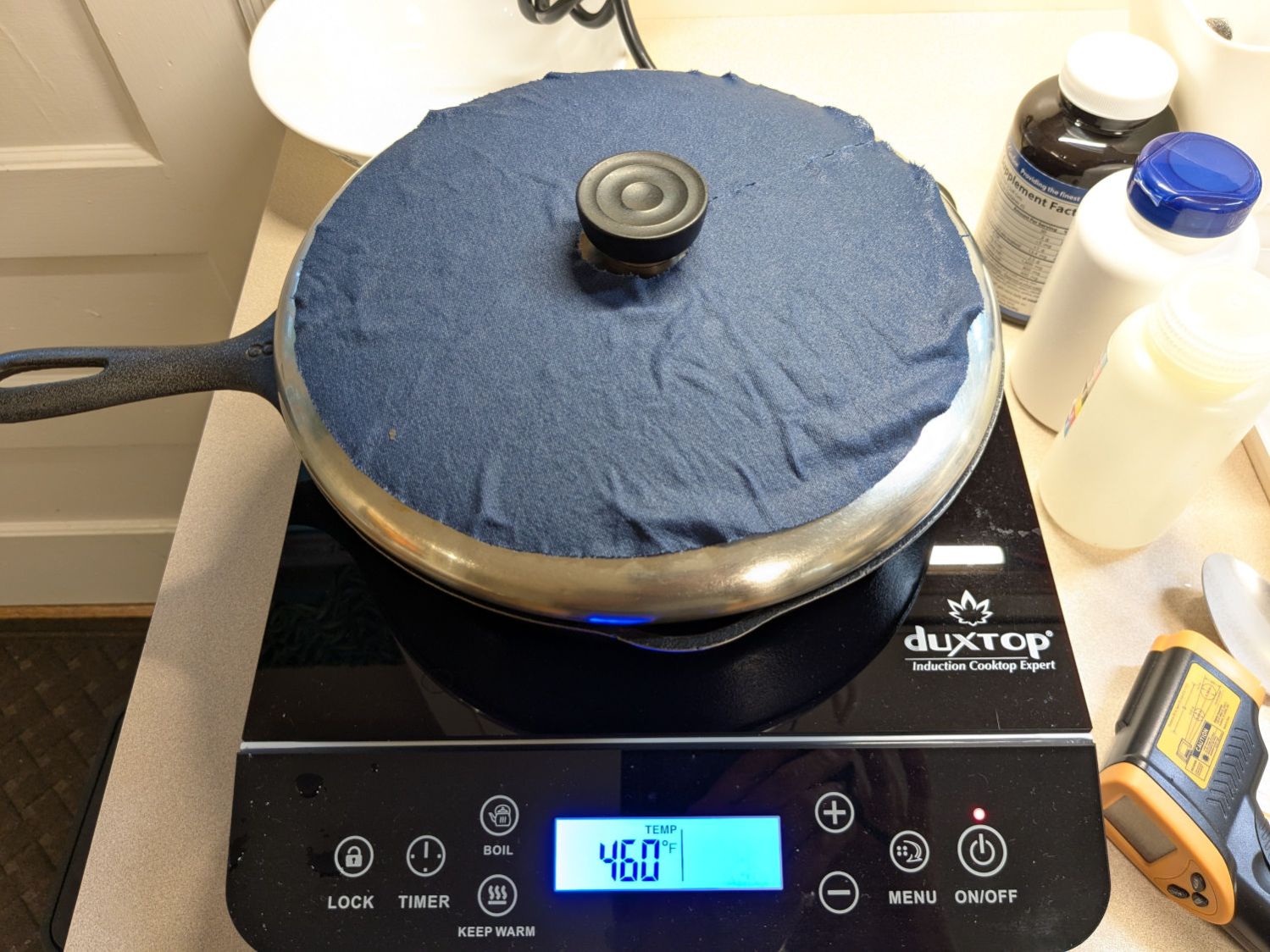
After an hour the surface temperature was around 150 °F, so I covered the pan with a water-cooled lid to see if any vapor condensed on it:
Alumina regeneration – lid cooling
It did, indeed, so I alternated covering and exposing the pan, which was likely a waste of my time, until the alumina dried enough that the lid didn’t collect any condensation. The whole process took just under four hours with the cooktop set to its maximum of 460 °F for most of the time.
The beads then cooled to room temperature in a covered dish:
Alumina regeneration – final cooling
The beads weighed 626 g at the start of the adventure and sweated down to 593 g, parting with 33 g = 1.2 oz of water in the process for a loss of 5.6%. I have no idea how dry they are now, but they’re an ounce drier than before.
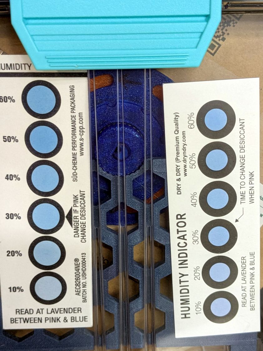
The indicator cards show the humidity is maybe a little over 10 %RH:
PolyDryer – TPU base – 10pctRH cards
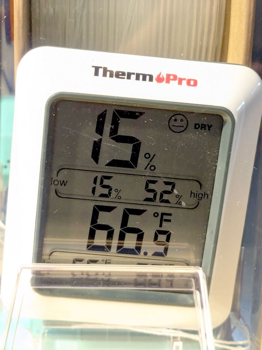
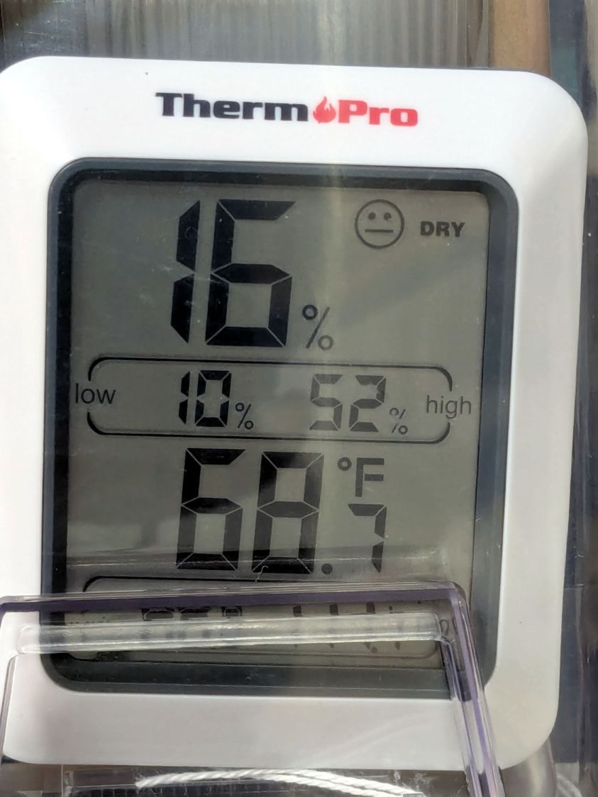
The meter jammed in the other end of the box splits the difference at 15 %RH:
PolyDryer – TPU base – 15pctRH TP
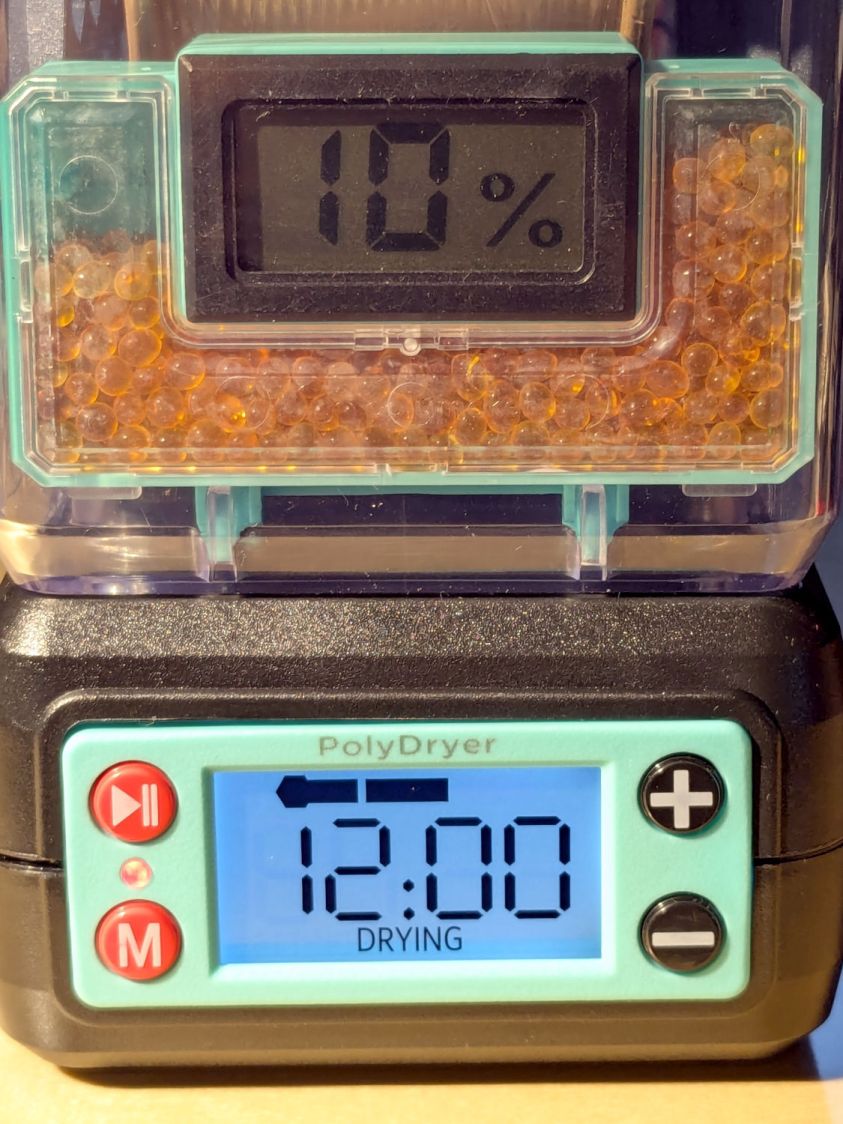
Put the box atop the improved PolyDryer, set it for the recommended 12 hours with “two bars” of oomph (which may roughly correspond to the temperature), and fire it up.
The OEM meter occasionally glitches to 10 %RH:
PolyDryer – TPU dry 1200h – 10pctRH glitch OEM
That type of humidity meter apparently reports values from 10 %RH upward, so this seems like the kind of glitch where the reading jams at one end of the range due to the sensor opening up / shorting / misbehaving. It does not correlate with any nearby electrical activity due to fans / heaters / 3D printers / whatever.
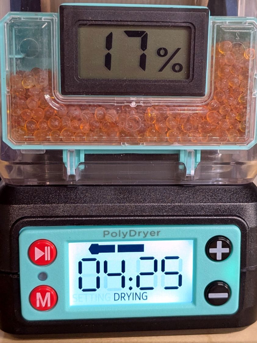
A little under eight hours later, it shows 17 %RH:
PolyDryer – TPU dry 0425h – 17pctRH OEM
Although it still has glitches to 10 %RH.
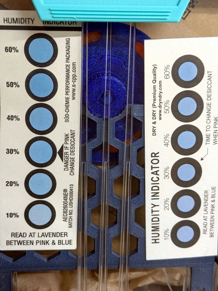
The cards look about the same, although I could be persuaded the 10% spots look ever so slightly more blue:
PolyDryer – TPU dry 0425h – 10pctRH cards
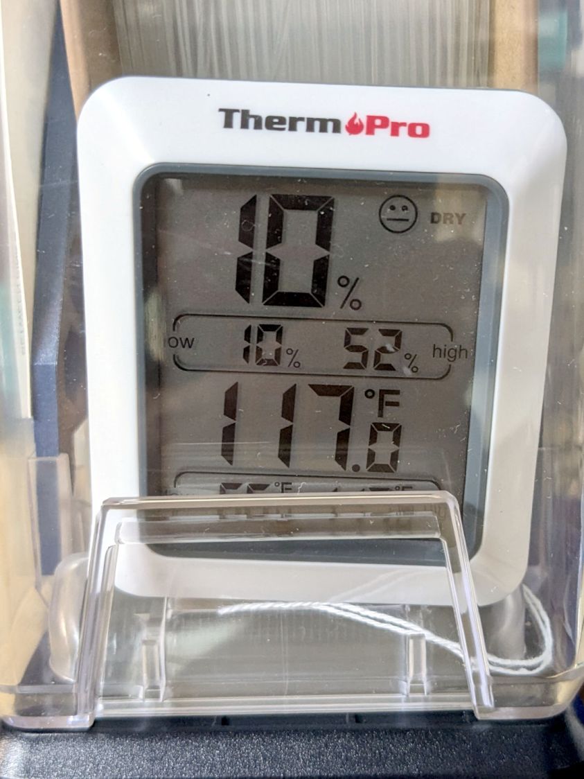
The meter in the back shows it’s toasty in there:
PolyDryer – TPU dry 0425h – 10pctRH TP
A psychrometric chart shows heating air from 66 °F & 15 %RH to 117 °F will put it at 3 %RH without removing any water vapor. This is far below the level my cheap “instrumentation” can measure, but it does suggest the meters should bottom out, regardless of whatever the silica gel is doing.
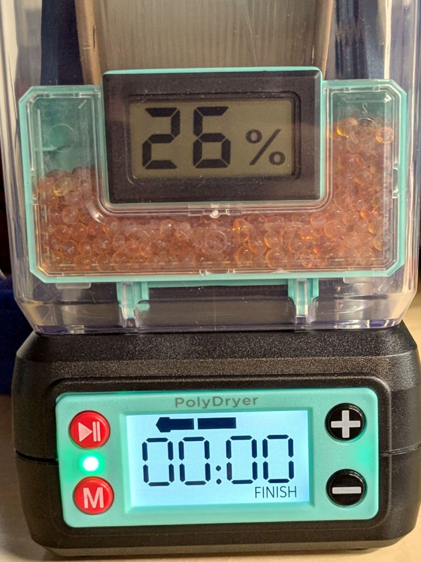
Allowing six hours to cool down & stabilize after the PolyDryer turns off in the middle of the night (because for science does not include all-nighters) shows a rebound to 26 %RH on the OEM meter:
PolyDryer – TPU dry 0000h – 26pctRH OEM
The cards remain unchanged:
PolyDryer – TPU dry 0000h – 10pctRH cards
The meter in the back again splits the difference at 16 %RH:
PolyDryer – TPU dry 0000h – 16pctRH TP
I pulled the larger meter and both cards out of the box.
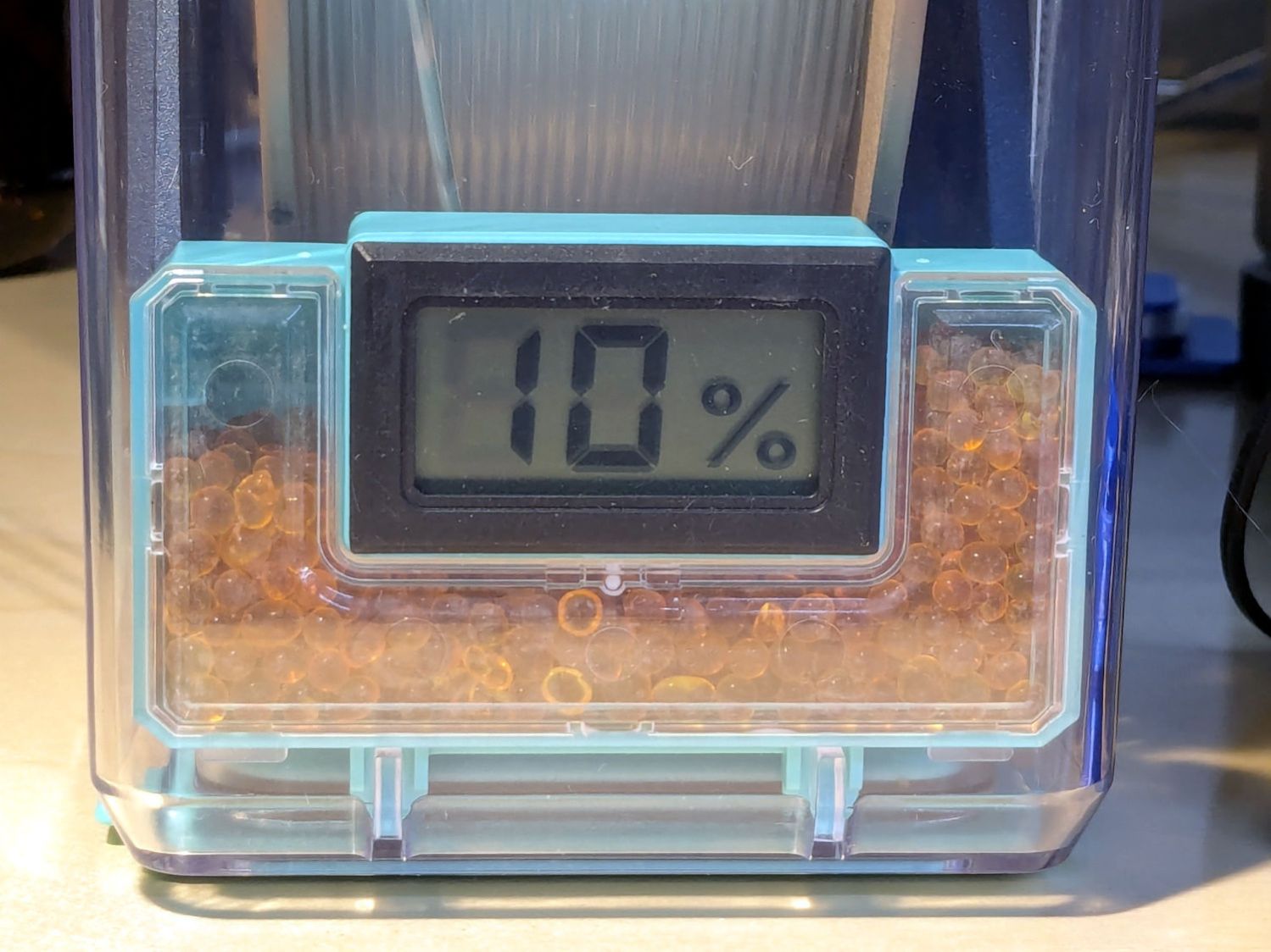
After sitting undisturbed for a day, the OEM meter in the box stabilized at 10 %RH:
PolyDryer – TPU post dry – 10pctRH OEM
The card agrees, to the best of its limited resolution:
PolyDryer – TPU post dry – 10pctRH card
The silica gel weighs 25.0 g, exactly what it did when I loaded the meter case. I think the scale’s 0.1 g resolution exceeds its accuracy, but even if the silica gel weighed 25.2 g ≅ 0.8 % water the humidity would be under 5 %RH.
As far as I can tell:
The filament on the spool isn’t outgassing water vapor
The air in the TPU box remains under 15-ish %RH at normal basement temperature
Running a PolyDryer cycle at 15-ish %RH doesn’t stuff any more water vapor in the silica gel
Cheap humidity meters lack accuracy around 15-ish %RH
Humidity meters take longer than you think to stabilize
Humidity indicating cards may be as good as you (well, I) need
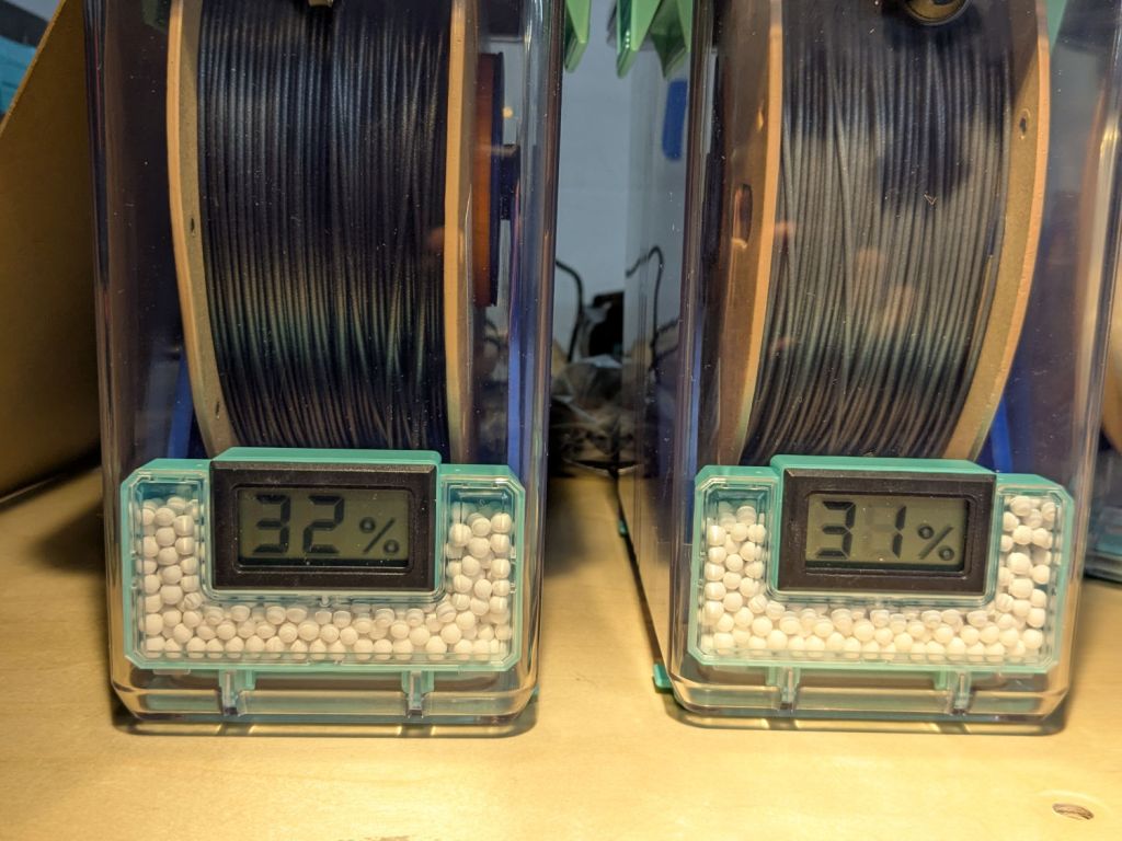
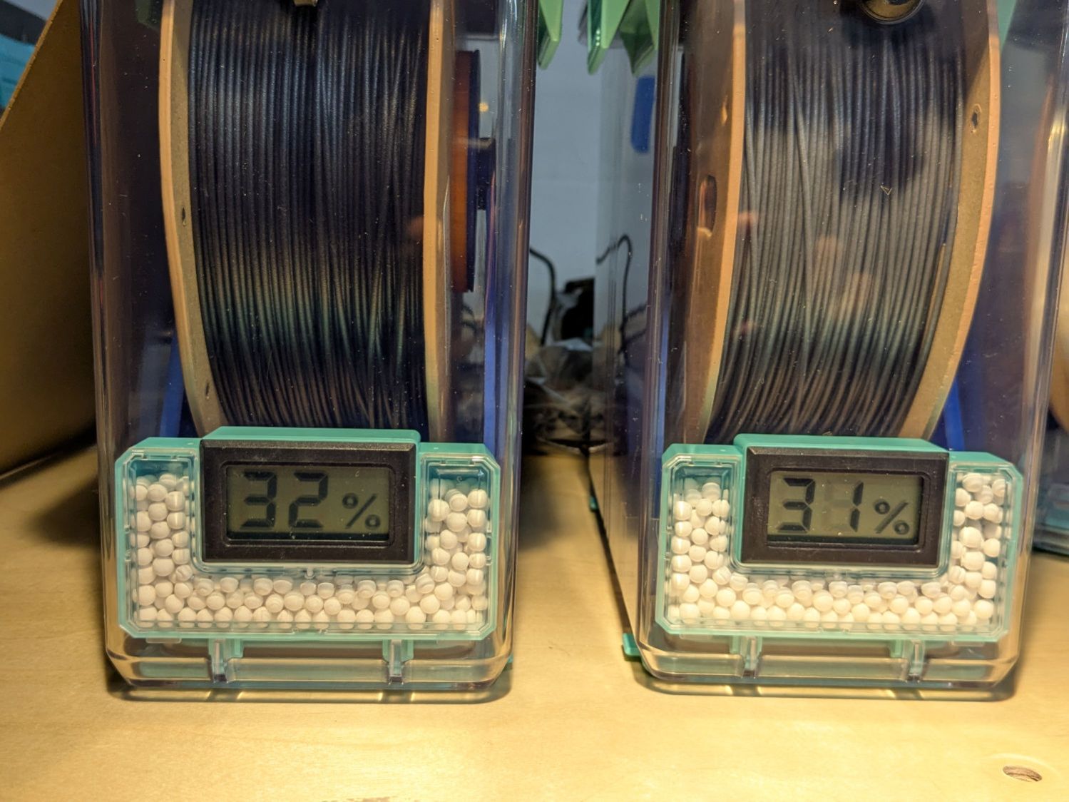
A pair of PolyDryer boxes has been holding black and gray PETG-CF for a while:
PolyDryer – PETG-CF – 32 pctRH Black 31 pctRF Gray
A few days ago I slipped humidity indicator cards into the boxes:
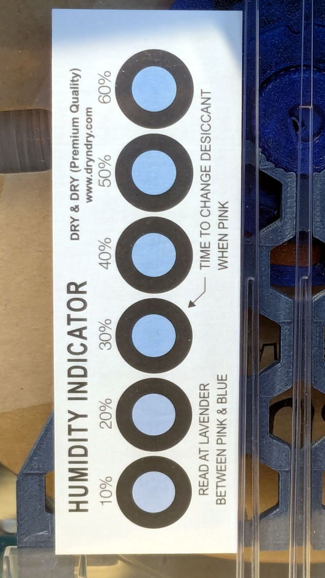
The black PETG-CF card suggests 30 to 40 %RH:
PolyDryer – PETG-CF – 32 pctRH Black test card
Yes, I dropped that card into the box upside-down.
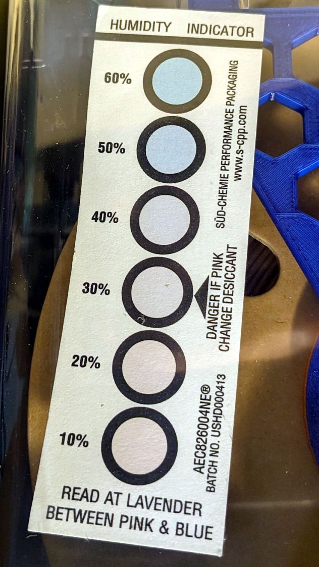
The gray PETG-CF card shows similar results:
PolyDryer – PETG-CF – 31 pctRF Gray test card
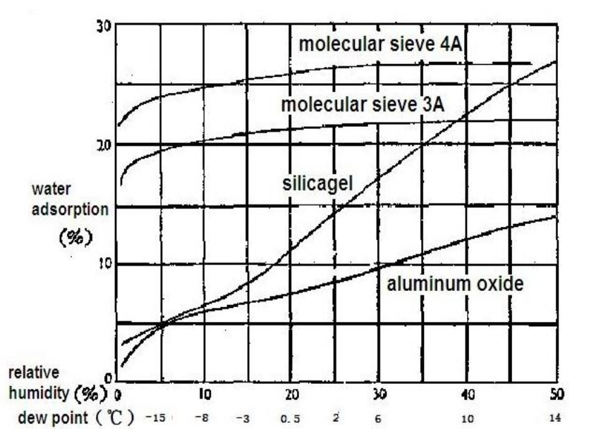
The desiccant in the black PETG-CF box weighed 80.9 g, a gain of 5.9 g = 10.8%. The chart suggests that corresponds to 35 to 40 %RH:
Desiccant adsorption vs humidity
The gray PETG-CF box had 102.0 g of desiccant. I apparently loaded 25 g in the meter container and 70 g in seven tea bags, but I don’t trust those numbers enough to go any further.
Unlike the black PETG box mismatch, these black PETG-CF numbers seem plausible. The results may depend on allowing far more time for the filament + air to equilibrate with the desiccant tucked in its containers than the days I’ve been giving it.
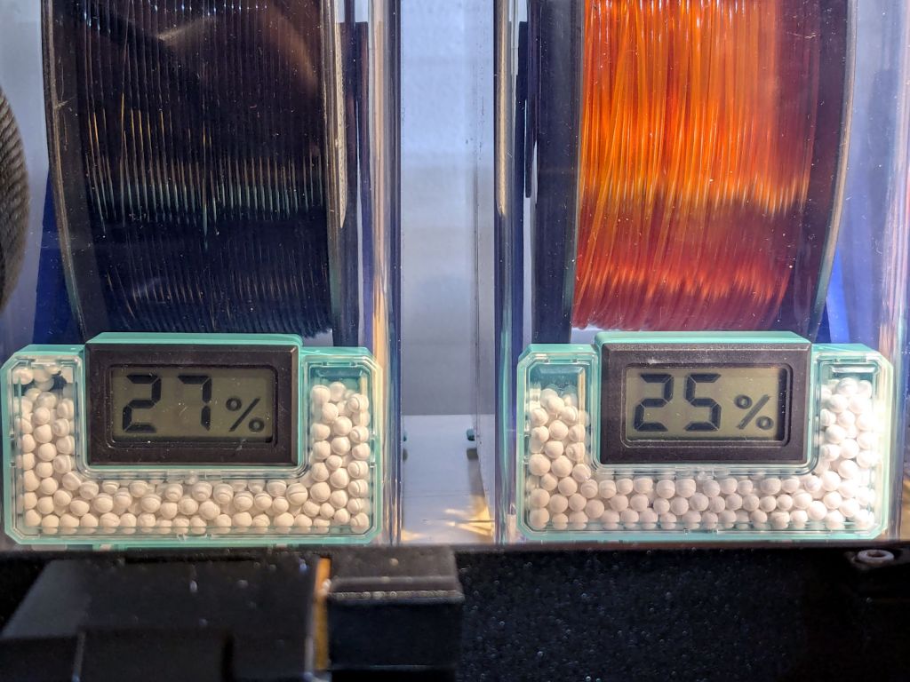
An adjacent pair of PolyDryer boxes have black and orange PETG filament:
PolyDryer – PETG – 27 pctRH Black 25 pctRH Orange
They’ve been sitting closed up for a week or so, with only 25 g of activated alumina in the desiccant holder (no tea bags with additional desiccant) pulling moisture out of their air and, presumably, filament.
The desiccant from the black filament weighed 29.0 g, showing it pulled 4.0 g of water out of the air, 16% of its original weight.
The “aluminum oxide” curve shows 16% adsorption should correspond to more than 50% RH, so the numbers don’t quite match up. On the other paw, I don’t know how much I can trust the meter accuracy.
I replaced the desiccant with 25 g of silica gel, tucked a humidity indicating card into the box, and snapped it closed again. The orange PETG box also got an indicating card so I can compare results.
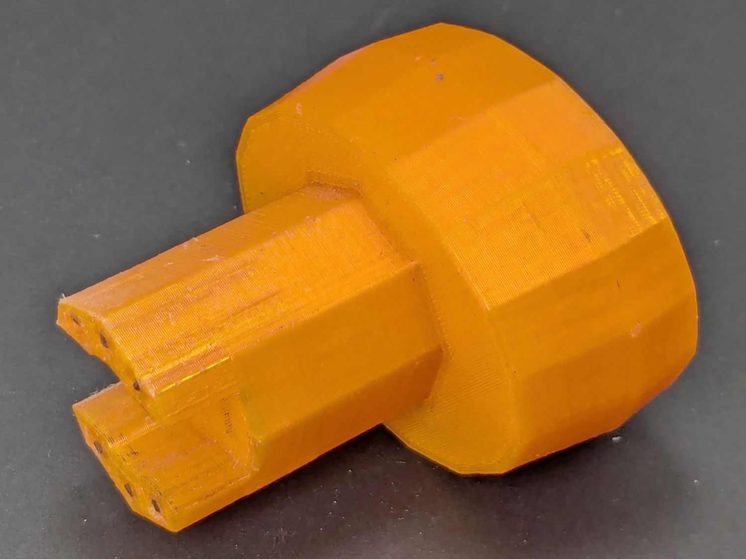
Mary found the wrench I made five years ago in the bottom of her tool bucket:
Hose Valve Knob – five years later
Having moved away from the garden with all the valves that wrench turned, it can now go into the 3D Printed Sample Box for use in the unlikely event I ever give another talk on the subject.
I’d design it differently these days, what with BOSL2 in my sails, but it got the job done.