The Smell of Molten Projects in the Morning

Ed Nisley's Blog: Shop notes, electronics, firmware, machinery, 3D printing, laser cuttery, and curiosities. Contents: 100% human thinking, 0% AI slop.

Category: Recumbent Bicycling

Cruisin’ the streets

  • Bafang Motor: Chain Gap Filler

    Bafang Motor: Chain Gap Filler

    When the chain falls off the top of the chainring toward the motor, the part remaining engaged with the chainring will inevitably drag the rest into the gap between the motor and the chainring spider, whereupon it will jam firmly in place and be almost impossible to extract. Preventing this means filling the gap, which required several iterations:

    Bafang motor gap filler - prototypes
    Bafang motor gap filler – prototypes

    The Bafang motor has a cover held in place by seven M3 flat-head screws, shown here below a test filler using pan head screws:

    Bafang motor gap filler - installed
    Bafang motor gap filler – installed

    Contrary to what you might think, the five screws that obviously sit on five points of a hexagon do not in fact sit 60° apart. How you find this out is by making the obvious layout, including the two screws bracketing the pinion gear in the lower right, then applying windage:

    Bafang motor housing gap filler - hole adjustments
    Bafang motor housing gap filler – hole adjustments

    That’s one of the paper templates seen above, with laser-cut holes 60° apart and ugly holes punched at the actual screw locations. Then you scan and overlay that image with the LightBurn layout and twiddle the hole locations to make the answer come out right:

    Bafang motor housing gap filler - hole adjustments - LB overlay
    Bafang motor housing gap filler – hole adjustments – LB overlay

    With that in hand, I cut a 1 mm acrylic shape to measure the clearance between the motor + filler and the chainring spider, with pan-head screws replacing the original flat-head screws:

    Bafang motor gap filler - top view
    Bafang motor gap filler – top view

    That’s a single piece of 2.5 mm acrylic I used after discovering a pair of the 1 mm acrylic shapes fit with space to spare: hooray for rapid prototyping.

    A test chain drop suggested it might suffice:

    Bafang motor gap filler - test
    Bafang motor gap filler – test

    If I were so inclined, 3 mm acrylic with countersunk holes and slightly longer flat-head screws would probably work, but I’ll use this until it fails to prevent a chain snag.

    The careful observer will have noted the stress crack extending radially inward from the upper-right screw, which I am carefully avoiding doing anything about, pending the aforementioned failure.

    The LightBurn layout as a GitHub Gist:

    Loading
    Sorry, something went wrong. Reload?
    Sorry, we cannot display this file.
    Sorry, this file is invalid so it cannot be displayed.

  • Tour Easy Running Light: Heatsink Machining

    Tour Easy Running Light: Heatsink Machining

    Having acquired some thick-wall (1 inch OD, ¾ inch ID) aluminum tube, making the LED heatsink and lens holder for a running light generates a lot less scrap. A new doodle gives the dimensions in a rather Picasso-ish layout:

    Running Light - dimension doodles
    Running Light – dimension doodles

    The back end of the tube gets turned down to 23 mm OD and cleaned up to 19 mm ID, then scored to give the epoxy something to grip:

    Front Running Light - Heatsink shell scoring
    Front Running Light – Heatsink shell scoring

    The front end gets bored to 22.5 mm for the lens holder and has its OD cleaned up to 25 mm:

    Front Running Light - finished shell
    Front Running Light – finished shell

    Clean up the end of a ¾ inch rod to 19 mm OD, knurl it a little to increase the OD ever so slightly and improve its griptivity, slice off a bit more than 10 mm, butter it up with JB Weld epoxy, and shove it into the shell with its front end aligned and its back end sticking out:

    Front Running Light - epoxied plug in shell - rear
    Front Running Light – epoxied plug in shell – rear

    Face off the back end and the front end looks fine as assembled:

    Front Running Light - epoxied plug in shell - front
    Front Running Light – epoxied plug in shell – front

    Grab it in the Sherline mill’s three jaw chuck to:

    • Drill & tap the M3 central hole for the stud holding the circuit plate to the back end
    • Drill 1.6 mm blind holes for the circuit plate pins
    • Drill 2 mm through holes for the LED wires, 60° apart

    Which looks like this from the front:

    Front Running Light - drilled heatsink - front
    Front Running Light – drilled heatsink – front

    And like this with the circuit plate screwed & glued to the rear:

    Front Running Light - circuit plate mounted
    Front Running Light – circuit plate mounted

    Clean up the OD of some ¾ inch PVC pipe to 25 mm, bore it out to 23 mm.

    While the Sherline is set up, drill a pair of 2 mm holes in the lens holder for the wires, aligned so they’ll match the heatsink holes.

    Because we live in the future, laser-cut the rear cap from some edge-lit acrylic with a black inner disk:

    Front Running Light - PVC tube - end cap
    Front Running Light – PVC tube – end cap

    Cutting that cap with the notch included is now trivially easy, compared to the previous machining.

    Now for some circuitry …

  • Tour Easy: SJCAM C100+ Mount

    Tour Easy: SJCAM C100+ Mount

    The batteries (which are no longer available) and the control buttons have worn out on the SJCAM M20 camera on the back of my Tour Easy, so a replacement is in order:

    Tour Easy - SJCAM C100 mount - installed
    Tour Easy – SJCAM C100 mount – installed

    It’s an SJCAM C100+ in its waterproof housing, screwed to a block descended from the M20 mount:

    SJCAM C100 Mount - solid model
    SJCAM C100 Mount – solid model

    The C100+ has a non-replaceable lithium pouch battery that may not last for the hour or so we generally ride, but at least this is a starting point for seeing how the thing works.

    The PrusaSlicer preview shows the support structure inside the seat rail arches:

    SJCAM C100 Mount - slicer
    SJCAM C100 Mount – slicer

    That appears under the four central facets of each arch, where I “painted” the support enforcers, because the automagic supports fill the entire arch and are basically impossible to pry off.

    The hole between the ears on the top holds an aluminum tab intended to diffuse the wobble from that tall camera. A laser-cut chipboard template simplified drilling & cutting the tab from an aluminum sheet:

    Tour Easy - SJCAM C100 mount - test fit
    Tour Easy – SJCAM C100 mount – test fit

    The tab and the brass inserts are held in place with JB Weld Plastic Bonder, my new go-to adhesive for such things.

    The camera includes WiFi and the inevitable app lets you download images without opening the case. Because I’ll be charging the camera after each ride, I may as well just haul the whole thing inside, plug it into a USB port, and proceed as before.

    For future reference, the manual details the operating modes:

    SJCAM C100 Manual - Modes
    SJCAM C100 Manual – Modes

    Because the camera powers up with WiFi enabled and I have no plans to communicate with it while riding, the startup sequence will be:

    • Long-press to power on
    • Double-click to disable WiFi
    • Single-click to start recording

    The OpenSCAD source code as a GitHub Gist:

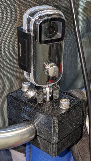
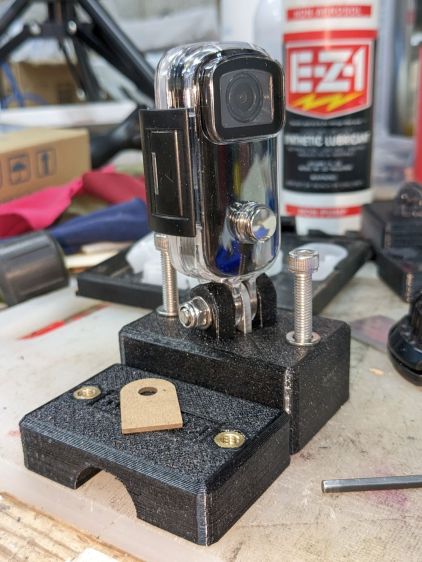
    // SJCAM C100+ Camera Mount for Tour Easy seat back rail
    // Ed Nisley – KE4ZNU
    // 2023-04
    /* [Layout Options] */
    LookAngle = -20; // camera angle, looking backwards = 0°
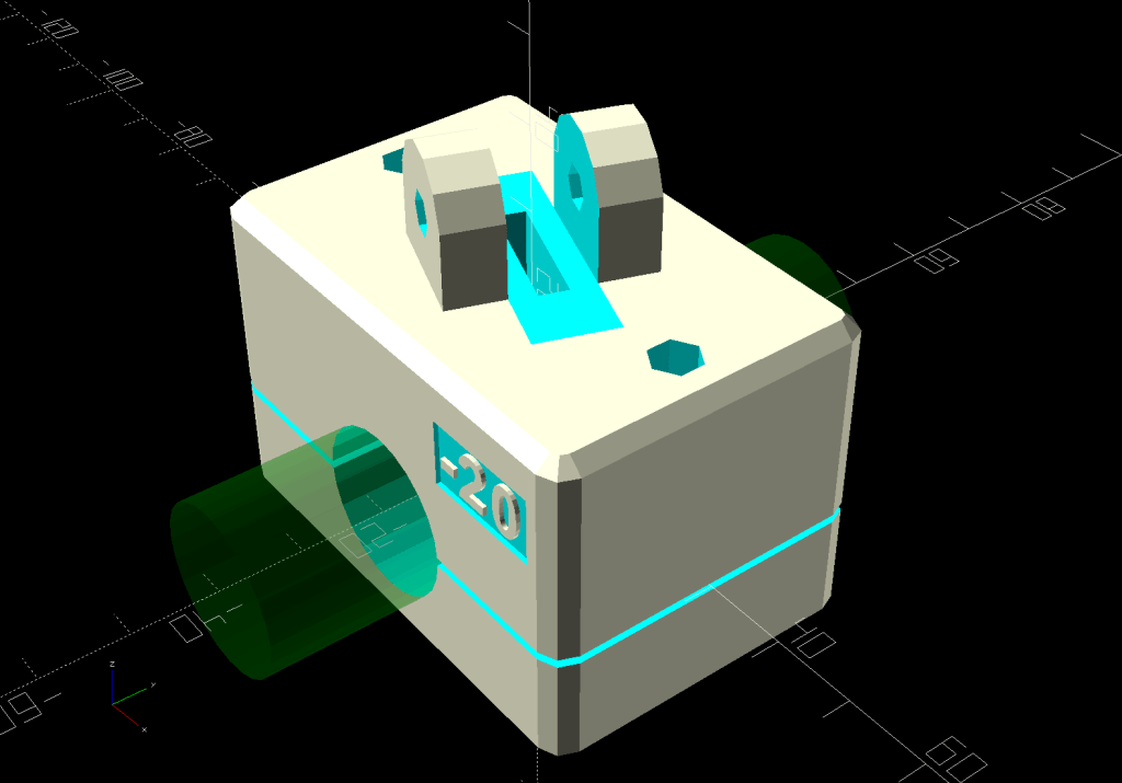
    Layout = "Show"; // [Show,Build]
    /* [Hidden] */
    ThreadWidth = 0.40;
    ThreadThick = 0.25;
    HoleWindage = 0.2;
    Protrusion = 0.1;
    ID = 0;
    OD = 1;
    LENGTH = 2;
    //—–
    // Dimensions
    ClampScrew = [5.0,10.0,40.0]; // ID=thread OD=washer LENGTH=total
    ClampInsert = [5.0,7.5,10.5]; // brass insert
    MountScrew = [5.0,10.0,23.0]; // ID=thread OD=washer LENGTH=under nut
    MountInsert = [5.0,7.5,10.5]; // ID=screw OD, OD=knurl dia
    EmbossDepth = 2*ThreadThick + Protrusion; // recess depth + Protrusion beyond surface
    DebossHeight = EmbossDepth; // text height + Protrusion into part
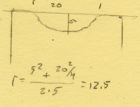
    RailOD = 20.0; // slightly elliptical in bent section
    RailSides = 2*3*4;
    ClampOA = [60.0,40.0,ClampScrew[LENGTH]]; // set clamp size to avoid weird screw spacing
    echo(ClampOA = ClampOA);
    ClampScrewOC = IntegerMultiple(ClampOA.x – ClampScrew[OD] – 10*ThreadWidth,1.0);
    echo(ClampScrewOC = ClampScrewOC);
    ClampOffset = 5.0; // in case we need more room on top
    ClampRadius = 3.0;
    ClampSides = 8;
    Kerf = 1.0; // slice through the middle
    // center mount blade, Z = depth into block
    MountBlade = [15.0 + 2*HoleWindage,
    3.0 + 2*HoleWindage,
    (ClampOA.z – RailOD + ClampOffset)/2 – 4*ThreadThick + Protrusion];
    echo(MountBlade = MountBlade);
    MountRadius = MountBlade.x / 2;
    MountGap = 9.5; // camera mount gap around center blade
    MountOffset = [0,0,7.0]; // mount hole offset from block surface
    FadeColor = "Green";
    FadeAlpha = 0.25;
    //—–
    // Useful routines
    function IntegerMultiple(Size,Unit) = Unit * ceil(Size / Unit);
    module PolyCyl(Dia,Height,ForceSides=0) { // based on nophead's polyholes
    Sides = (ForceSides != 0) ? ForceSides : (ceil(Dia) + 2);
    FixDia = Dia / cos(180/Sides);
    cylinder(r=(FixDia + HoleWindage)/2,
    h=Height,
    $fn=Sides);
    }
    //—–
    // Clamp
    // Grips seat frame rail
    // Origin at middle of seat rail, X rearward, Y parallel to seat frame rail
    // Block offset raises whole thing
    module Clamp() {
    difference() {
    translate([0,0,ClampOffset]) {
    difference() {
    union() {
    hull() // the main block
    for (i=[-1,1], j=[-1,1], k=[-1,1])
    translate([i*(ClampOA.x – 2*ClampRadius)/2,
    j*(ClampOA.y – 2*ClampRadius)/2,
    k*(ClampOA.z – 2*ClampRadius)/2])
    sphere(r=ClampRadius/cos(180/ClampSides),$fn=ClampSides);
    hull() // camera mount boss
    for (k=[0,1])
    translate([0,0,k*(MountOffset.z) + ClampOA.z/2])
    rotate([0,90,LookAngle + 90]) rotate(180/12)
    cylinder(r=MountRadius,h=MountScrew[LENGTH],center=true,$fn=12);
    }
    for (i=[-1,1]) // clamp inserts
    translate([i*ClampScrewOC/2,0,-(ClampOA.z/2 + Protrusion)])
    rotate(180/6)
    PolyCyl(ClampInsert[OD],ClampInsert[LENGTH],6);
    for (i=[-1,1]) // clamp screw holes
    translate([i*ClampScrewOC/2,0,-ClampOA.z])
    rotate(180/6)
    PolyCyl(ClampScrew[ID],2*ClampOA.z,6);
    translate([0,0,ClampOA.z/2 – (MountBlade.z/2 – Protrusion/2)]) // camera center blade
    rotate(LookAngle)
    cube(MountBlade,center=true);
    rotate(LookAngle + 90) // camera mount boss slot
    translate([0,0,ClampOA.z/2 + 2*MountRadius])
    cube([MountGap,4*MountRadius,4*MountRadius],center=true);
    translate([0,0,ClampOA.z/2 + MountOffset.z]) // camera mount boss hole
    rotate([90,0,LookAngle])
    cylinder(d=MountScrew[ID],h=4*MountGap,center=true,$fn=6);
    translate([0.3*ClampOA.x, // recess for LookAngle legend
    -(ClampOA.y/2 – (EmbossDepth – Protrusion)/2),
    ClampOA.z/4])
    cube([15,EmbossDepth,8],center=true);
    translate([0,0,-ClampOA.z/2 + (EmbossDepth – Protrusion)/2]) // recess for ID legend
    cube([35,10,EmbossDepth],center=true);
    }
    translate([0.3*ClampOA.x, // LookAngle legend
    -ClampOA.y/2 + DebossHeight + Protrusion/2,
    ClampOA.z/4])
    rotate([90,0,00])
    linear_extrude(height=DebossHeight,convexity=20)
    text(text=str(LookAngle),size=6,spacing=1.20,
    font="Arial:style:Bold",halign="center",valign="center");
    translate([0,0,-ClampOA.z/2]) // ID legend
    linear_extrude(height=DebossHeight,convexity=20)
    mirror([0,1,0])
    text(text="KE4ZNU",size=5,spacing=1.20,
    font="Arial:style:Bold",halign="center",valign="center");
    }
    cube([2*ClampOA.x,2*ClampOA.y,Kerf],center=true); // split across rail
    rotate([90,0,0]) // seat rail
    cylinder(d=RailOD,h=2*ClampOA.y,$fn=RailSides,center=true);
    }
    }
    //—–
    // Build things
    // Layouts for design & tweaking
    if (Layout == "Show") {
    Clamp();
    color(FadeColor,FadeAlpha)
    rotate([90,0,0])
    cylinder(d=RailOD,h=2*ClampOA.y,$fn=RailSides,center=true);
    }
    // Build layout
    if (Layout == "Build") {
    translate([0,0.7*ClampOA.y,0])
    difference() {
    translate([0,0,-Kerf/2])
    Clamp();
    translate([0,0,-ClampOA.z])
    cube(2*ClampOA,center=true);
    }
    translate([0,-0.7*ClampOA.y,-0])
    difference() {
    translate([0,0,-Kerf/2])
    rotate([0,180,0])
    Clamp();
    translate([0,0,-ClampOA.z])
    cube(2*ClampOA,center=true);
    }
    }

  • Another CatEye Cadence Sensor Magnet Mount

    Another CatEye Cadence Sensor Magnet Mount

    The stock Bafang pedal cranks measure 170 mm on centers between the bottom bracket shaft and the pedal spindle. Having grown accustomed to the 165 mm cranks from Mary’s bike, I got a set of cheap 160 mm cranks to feel if there was any difference:

    Bafang vs ProWheel crank forging
    Bafang vs ProWheel crank forging

    The bottom crank has a quick-and-dirty adaptation of the magnet mount for the Lekkie Buzz Bar offset cranks, but, of course, the 160 mm cranks have an entirely different profile. They are also heavier and more crudely forged, which is about what you’d (well, I’d) expect.

    Also unlike the Lekkie cranks, neither the Bafang nor the Prowheel cranks correct the Bafang motor’s offset, so I’m using the left-side Kneesaver from the old cranks, which turns out to be close enough.

    Modeling the profile started with an infrequently used contour gauge:

    CatEye Magnet holder - ProWheel crank profile tests
    CatEye Magnet holder – ProWheel crank profile tests

    The black 3D printed mount in the upper right fit the Bafang crank and appears in the top photo.

    Transferring the new contour to paper and applying the Chord Equation got the radius of the not-quite circle:

    CatEye magnet crank adapter - chord radius
    CatEye magnet crank adapter – chord radius

    Knowing the size of the magnet and the radius of the circle, drawing the profile in LightBurn was straightforward:

    CatEye magnet crank adapter - framed
    CatEye magnet crank adapter – framed

    Applying the laser cutter to MDF produced the two successive test-fit pieces in the picture while figuring out how much stickout the magnet needed beyond the inner crank face to reach the sensor. LightBurn’s Node Editor simplified adjusting the size: drag-select a group of nodes, then move them in precise increments with the arrow keys.

    Export the profile from LightBurn as an SVG file, import it into OpenSCAD, and extrude it to the proper length:

    module CatEyeMagnet() {
    
    Magnet = [19.0,14.0,8.5];
    
    translate([0,75,0])
        linear_extrude(height=Magnet.y)
            import("CatEye magnet crank adapter.svg");
    
    }
    

    The translate puts the profile approximately at the XY origin. The center = true option moves the profile elsewhere on the XY plane, but does not center it, which may have something to do with the viewport used by LightBurn, the OpenSCAD version I’m using, or something else entirely.

    In any event, the 3D printed mount fits the crank and puts the magnet where it will do the most good:

    CatEye Magnet holder - ProWheel crank - installed
    CatEye Magnet holder – ProWheel crank – installed

    What looks like an obvious curvature mismatch comes from having the tape edge not quite squashed against the crank.

    I should poke a channel through it for a cable tie around the crank, but that 3M foam tape is really good stuff and hasn’t failed me yet.

  • Bafang DPC-18 Button Mollyguard

    Bafang DPC-18 Button Mollyguard

    I got the Bafang DPC-18 display for my Tour Easy specifically to put the control buttons on the handgrip, rather than the buttons on the left of the 500C display on Mary’s bike:

    Tour Easy Bafang - display 26 mi
    Tour Easy Bafang – display 26 mi

    The first pass put them on the left handgrip, just behind the thumb throttle:

    Bafang DPC-18 control buttons - initial mount
    Bafang DPC-18 control buttons – initial mount

    This turned out to be a catastrophically bad position, because the “buttons” extend all the way to the edge of the mount and trigger when pressed a fraction of a millimeter: the dark line visible under the light gray top is the entire range of motion.

    My resting hand position on the grip put the edge of my gloved index finger along the buttons, where it would inexorably nudge the + button until I was riding in assist level 9 (Rocket Sled) mode.

    One ride was enough to convince me those buttons needed a Mollyguard:

    PXL_20230321_233854755 - Bafang DPC-18 button Mollyguard - rear view
    PXL_20230321_233854755 – Bafang DPC-18 button Mollyguard – rear view

    It is, of course, a laser-cut piece of 1.5 mil black acrylic, held in place with hot-melt glue. Because the button housing isn’t mounted symmetrically on the handlebar, I cut a few paper templates before getting the position and size right.

    A view from the front shows the lip sticking up over the buttons:

    Bafang DPC-18 button Mollyguard - front view
    Bafang DPC-18 button Mollyguard – front view

    FWIW, the asymmetric mount put the buttons on the rider’s side of the flat handlebars found on contemporary upright city-rider style bikes. It makes perfect sense in that context, but didn’t help me in the least.

    With the Mollyguard in place, I rotated the whole button assembly around the handgrip to allow pushing the buttons with my thumb in its natural position.

    Now the assist level changes only when I want it to!

  • Bafang Motor Connector Gasket Replacement

    Bafang Motor Connector Gasket Replacement

    Reasonable people disagree as to the cause of the failure, but a replacement controller for the (new) Bafang motor I’m installing on my bike just arrived in the mail.

    Disassembling the motor is straightforward, except for the part where you must excavate an internal plug from the silicone snot gluing it into place, eventually revealing its socket:

    Bafang motor - interior gasket - connector
    Bafang motor – interior gasket – connector

    Regrettably, there seems no way to do that without destroying the dense closed-cell gasket around the connector:

    Bafang motor - interior gasket - damaged original
    Bafang motor – interior gasket – damaged original

    Equally regrettable: a replacement gasket wasn’t included with the replacement controller. Although I don’t have any of the specific foam, some marginally less dense foam from the Big Box o’ Padding seemed suitable for laser cuttery:

    Bafang motor - interior gasket - iterations
    Bafang motor – interior gasket – iterations

    The upper left prototype suggested a slightly larger rear bar that produced the gasket in front, which fit snugly:

    Bafang motor - interior gasket - test fit
    Bafang motor – interior gasket – test fit

    It lacks the latch cutout, but the foam is squishy and I expect to never touch it again.

    A generous glob of hot melt glue holds everything in place:

    Bafang motor - interior gasket - replacement glued
    Bafang motor – interior gasket – replacement glued

    Although the usual Youtube videos show folks slathering RTV silicone caulk on these connectors, that’s a Very Bad Idea™, because RTV caulk releases acetic acid as it cures. That’s not a problem in the open-air siding-and-lumber environment the caulk was intended for, but sealing a glob of the stuff inside an enclosure will eventually corrode all of the electronics therein.

    Cutting intricate doodads has become trivially easy: if you can draw it, you can pretty much cut it, just like that:

    Bafang motor connector gasket - LB layout
    Bafang motor connector gasket – LB layout

    That was the easy part, anyway.

  • Bafang Triangle Plate Rework

    Bafang Triangle Plate Rework

    The time has come to add a Bafang mid-drive motor to my Tour Easy recumbent, much like the one Mary has been using for the last two years. When I got to the point of installing the motor in the bottom bracket shell, this happened:

    Bafang Triangle Plate - jammed screw
    Bafang Triangle Plate – jammed screw

    It turns out the triangle plate has slightly misplaced bolt holes:

    Bafang Triangle Plate - misplaced bolt holes
    Bafang Triangle Plate – misplaced bolt holes

    If you look very carefully, you’ll see the holes sit just slightly above the midline of those ears. The additional fractional millimeter below the holes touches the motor end bell and prevents them from lining up with the tapped holes.

    Normally, you’d just hit the plate with a file and be done with it, but it’s ferociously hardened steel: a file bounces right off.

    I deployed a Dremel sanding drum above the ShopVac’s snout to catch the abrasive dust, eroded just enough steel to line up the holes, and everything now fits the way it should.

    Done!