Ed Nisley's Blog: Shop notes, electronics, firmware, machinery, 3D printing, laser cuttery, and curiosities. Contents: 100% human thinking, 0% AI slop.
After I mentioned I was thinking of repurposing the nearly unused lithium-ion batteries from the Wouxun KG-UV3D radios for a blinky light, Dragorn of Kismet introduced me to his Baofeng UV-5 radio. The radio itself seems to be the worst amateur radio you’d be willing to use, but when seen as a standardized battery and drop-in charger with a free radio and antenna tossed into the deal, it’s not all that bad:
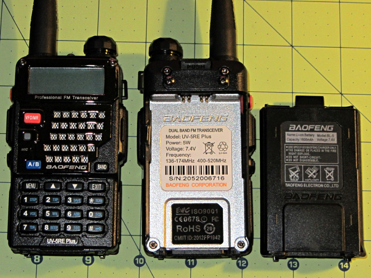
Baofeng UV-5RE radio – overview
The Wouxun and Baofeng 7.4 V batteries allegedly have similar capacities: 1700 vs 1800 mA·h. The Baofeng also has a 3800 (or 3600) mA·h pack that extends well below the base of the radio (not all large packs seem to be compatible with the UV-5RE radios I got); that would be roughly equivalent to the larger packs that power the Wouxun / APRS / voice gadgetry on the bike.
The Baofeng battery pack is smaller and has features that seem less likely to misbehave on a bike.
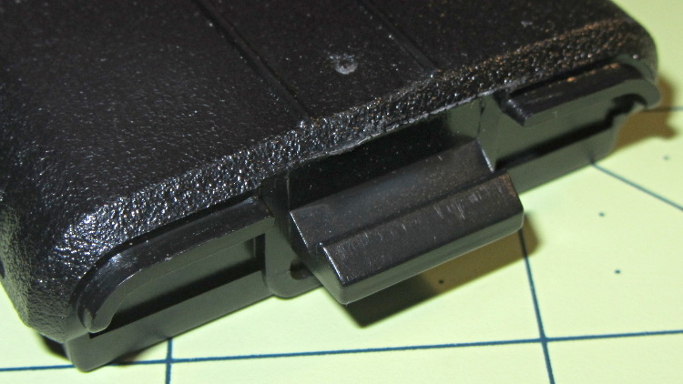
It has a latching tab with a ramp and a positive notch, with ridges around the edge that engage the radio shell:
Baofeng UV-5RE radio – battery latch tab
The radio body (which is what I must duplicate) has a movable latch tab above the battery contact pins, so the latch holds the battery into the compartment. The spring-loaded pin pairs are wired in parallel, presumably for redundant contact with each battery terminal:
Baofeng UV-5RE radio – battery compartment latch and contacts
The battery terminal pads are reasonably well protected by the tab:
Baofeng UV-5RE radio – battery contact pads
The battery slides into the radio compartment and latches with a snap. Two holes on the battery base engage a pair of pegs on the radio case:
Baofeng UV-5RE radio – battery base detail
The holes are rounded rectangles and the pegs have one corner sliced off. The pegs seem entirely too fragile and not well suited for 3D printing, so some metalwork may be in order. The pegs must resist only pulling forces perpendicular to the case back, not sliding forces, and the case constrains side-to-side motion.
The two square posts (with two others not shown) form the “feet” that support the radio when it’s standing on the desk or in the charger.
Now, to doodle up the dimensions and measure the actual capacity.
Speaking of capacity, BL-5 batteries on eBay range from $23 for “genuine Baofeng” that may or may not actually have that name on the label, all the way down to $8 for the usual no-name equivalent.
The horrible paint crazing came from “priming” the bare plywood scrap (yes, that’s a stray hole from its previous life) with a specialty white paint intended for plastic lawn furniture; it apparently gets along poorly with the forget-me-not fluorescent red topcoat. Doesn’t matter in this application and uses up more of both rattlecans, so it’s all good.
Of course, after tucking it in the bike’s underseat bag, I spotted the lost plate along the DCRT: now I have a spare!
A day or so after kvetching about that informal DCRT vehicle entrance to the head planner developing the Dutchess County Master Plan for bicycle & pedestrian facilities, this appeared:
DCRT Overocker Crossing – block on informal entrance
Notice the blue electrical junction box on the right? That can’t possibly be a Good Thing… but, so far, it doesn’t seem to bother anybody enough to repair it.
Those missing ADA strips at Grand have been swept out, converting them into rough-bottomed trenches across the trail. At least they’re not quite so slip-prone, even if they’re still a tripping hazard.
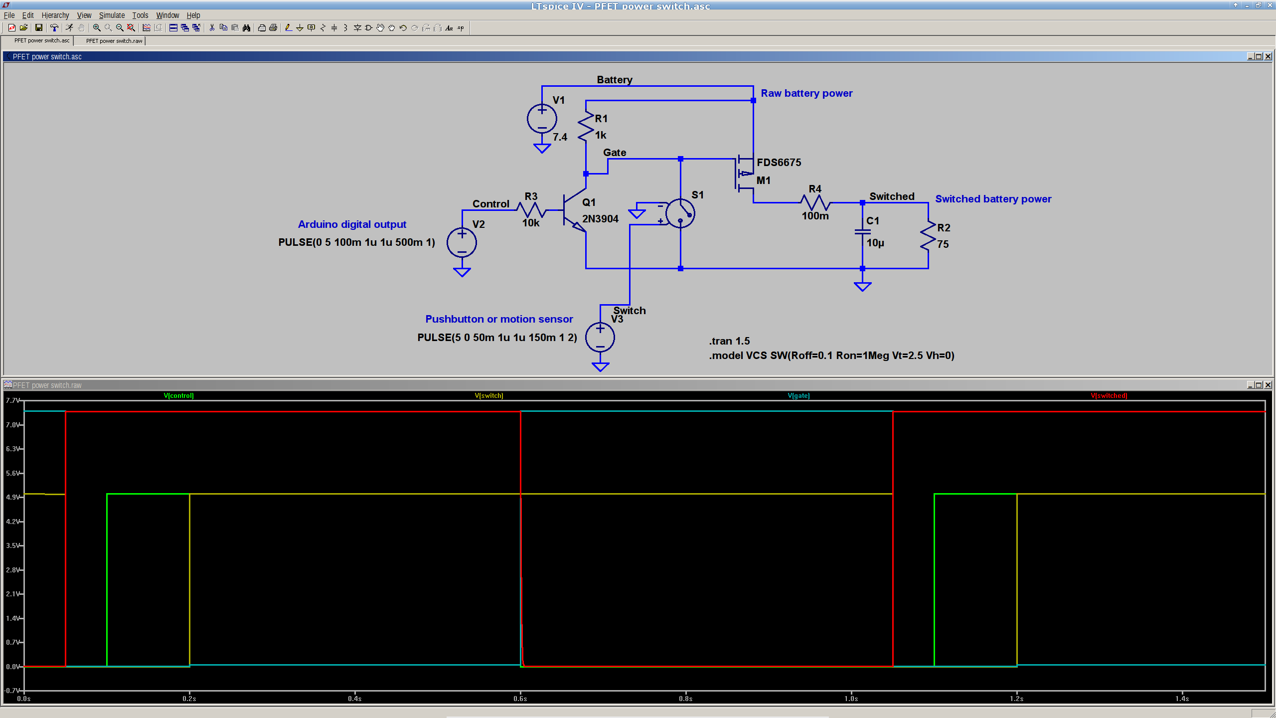
This is a simulation showing that a p-channel power MOSFET should work fine as a battery cutoff / switch for the bike taillight (clicky for many more dots):
P-MOSFET power switch
The general idea is to have a pushbutton or vibration sensor turn on the power, whereupon the Arduino wakes up and activates an output pin that holds the power on. When it’s time to shut down, the Arduino turns that output pin off, the power goes away, and everybody’s happy.
The MOSFET must be not only p-channel, but also have a logic-level gate, which is a rare and precious combination among cheap surplus MOSFETs. I’m hoping those FDS6675 MOSFETs work better than their package looks.
The capacitor and resistor over on the right simulate a reasonable load.
The voltage-controlled switch in the middle represents the vibration sensor, which is either shorted or open as determined by the voltage source at the bottom. There doesn’t seem to be any other Spice-ish way to do that.
The Arduino output, simulated by another voltage source drives the NPN transistor, which isolates the output pin from the 7.4 V (up to maybe 8.5 V when fully charged) Li-ion battery. It also isolates it from the switch, which would otherwise yank the output pin to ground if you pushed the button when the power was already on.
You’d want a few more pullup and pulldown resistors to ensure things stay where they’re put while the lights are out. I’d want to measure an actual vibration sensor; it may require a pulse stretcher to ensure the Arduino has enough time to wake up and smell the electrons.
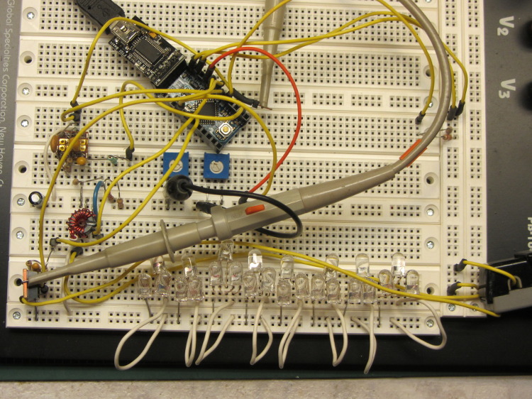
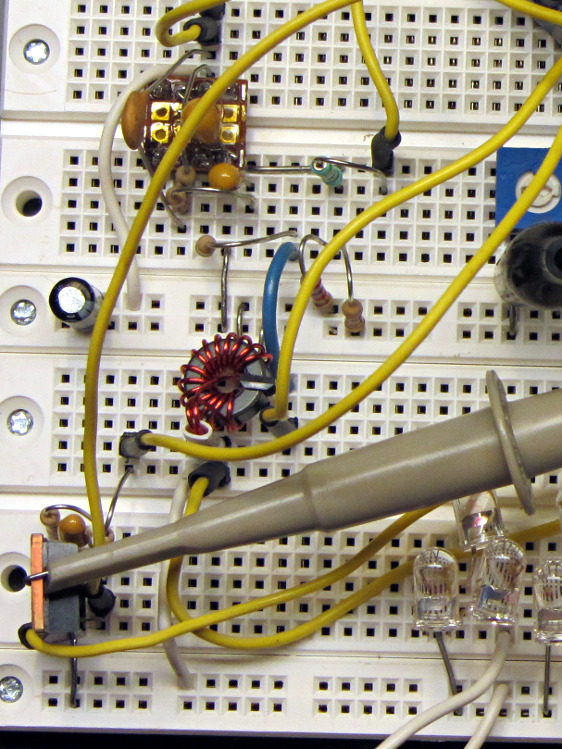
This hideous proof-of-concept lashup gathers a bunch of stuff I’ve been investigating into what’s definitely in the running for the most over-the-top LED blinky light ever:
Hall Effect LED Current Control – breadboard overview
The general idea:
A large-area bike taillight (tiny, narrow-beam, intense LEDs aren’t visible at a distance or off-axis)
Arduino Love closing the feedback loop (for programmatic blinkiness)
A closer look at the key analog parts:
Hall Effect LED Current Control – breadboard detail
The ferrite toroid near the middle surrounds that same “49E” Hall effect sensor. The ZVNL14 logic-level MOSFET in the lower right runs with about 2.4 V on the gate to put 120 mA through the LEDs. The cluster of parts just above it are the RC low-pass PWM filter, with the PWM running at 32 kHz. The snippet of perfboard near the top adapts a MAX4330 op amp to DIP pins. I used the twiddlepots to bring up the op amp and MOSFET circuitry by force-feeding bias and gate voltages.
The Arduino Pro Mini closes the feedback loop from current sensor to MOSFET gate. A knockoff Arduino Pro Mini is a $5 component, in onesies, delivered halfway around the planet. For low-volume stuff like this, you just build it right in and move on; there’s no reason to lay out a PCB with an ATmega328 chip and a handful of other parts. Unless you’re worried about power consumptions, as described below.
The schematic:
Hall Effect Current Feedback LED Driver – prototype schematic
The MAX4330 removes the Hall effect sensor’s VCC/2 bias, but it turns out the offset varies by enough from part to part and over temperature that a single twiddlepot setting won’t suffice. The RC filter near the middle of the schematic converts an Arduino PWM output into a voltage between 2.0 and 3.0 V, which puts more PWM resolution where it matters; the default 0.4% PWM steps are just too coarse. I think 16 bit PWM resolution would be A Very Good Thing here.
The first-pass program nulls the offset once, during the startup routine, but nulling whenever the LEDs turn off would be a Good Idea. The offset steps are 8 mV, about what you’d expect from 2/5 of the nominal 20 mV PWM increments. It ramps the offset up from zero, but you’d probably want to use a binary search.
The op amp has a voltage gain of about 28 that scales the toroid-plus-Hall-sensor output so that 500 mA in the winding produces 5 V. That gain isn’t quite high enough for the 120 mA I’m using for this collection of LEDs , but it makes the coefficient a nice round 0.10. It’d be good to have a calibrated current load, something around 100 mA, that would allow auto-calibration.
A 50% voltage divider lets the Arduino measure the nominal 7.4 V battery voltage and decide when to lower the current or change the blink pattern or kvetch about imminent blackout or something. Knowing both the battery voltage and the resistance of the current calibration load would let the program calculate the actual current for calibration. Given two calibration loads, then you could derive both the gain and the remaining offset; that’s likely too much trouble.
The Pro Mini board has a voltage regulator that provides +5 V for everything else in the circuit, which means putting the microcontroller into sleep mode won’t save any battery power. I think a p-channel MOSFET switch and a suicide output from the Arduino will be in order. A vibration sensor would give you auto power on and off, which would be a nice touch; MEMS sensors seem to want 3.3-ish V for supply and logic.
The entire lashup runs at about 60 mA with the LEDs turned off, which is way too high and may include some breadboard screwups; considerable reduction will be in order before this circuit makes any sense. The Hall effect sensor costs about 4 mA all by itself, plus another milliamp in the load resistor. The microcontroller should be around 10 – 20 mA, but the datasheet makes some assumptions that aren’t true for the Arduino runtime.
The program brute-forces the pulse timing, just to get this thing working. The main loop stalls while the LEDs are on, which is obviously a Bad Thing. The ADC conversions do some averaging, but I’m not confident it works well enough. The PWM output routine includes an entirely empirical delay to cover the filter time constants.
The blink pattern should be in a table. Given linear current control, you can have variable brightness; a “night taillight” mode that isn’t so shatteringly bright would be a Good Idea. The table might contain gate voltages for each current level, updated during the last pulse, so that the output would be Pretty Close at the beginning; you’d measure those values during startup.
A button or two for mode selection might be in order. Sealing buttons is always a problem, but this thing might not be totally waterproof anyway.
The first Wouxun (evidently pronounced “ocean”) KG-UV3D HT spent a month or two in my bike, lashed to a kludged version of the APRS+voice interface box and powered by its own lithium-ion pack. After I got the circuit worked out and built a duplicate, I picked up a second HT for Mary’s bike; as a result, that battery pack never got much use.
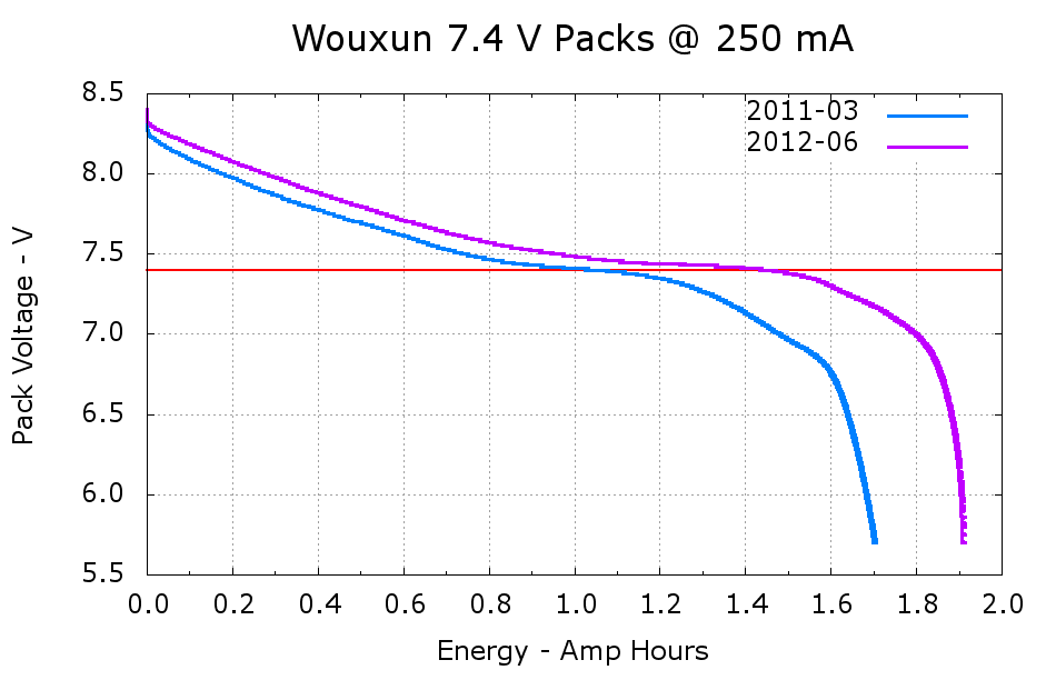
A pair of discharge tests shows the difference:
Wouxun 7.4 V Packs
The 2011-03 battery has almost exactly the rated 1.7 A·h capacity, at least if you’re willing to run it down to 6 V, and the 2012-06 pack delivers 1.9 A·h. Electronic gadgets measure state-of-charge using the battery voltage, so the older pack “looks” like it has much less capacity: it runs about 100 mV lower than the newer pack out to 1.2 A·h, then falls off the cliff. Looks to me like one of the two cells inside is fading faster than the other; so it goes.
I’m still thinking of using these to power some LED taillights, because they have a nice form factor and built-in latches: