The Smell of Molten Projects in the Morning

Ed Nisley's Blog: Shop notes, electronics, firmware, machinery, 3D printing, laser cuttery, and curiosities. Contents: 100% human thinking, 0% AI slop.

Category: Recumbent Bicycling

Cruisin’ the streets

  • Tour Easy Rear Running Light: First Light!

    Tour Easy Rear Running Light: First Light!

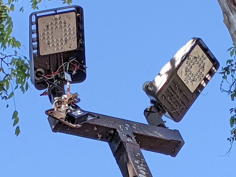
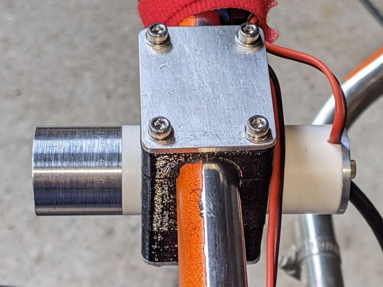
    The rear running light definitely has an industrial look:

    Tour Easy Rear Running Light - installed
    Tour Easy Rear Running Light – installed

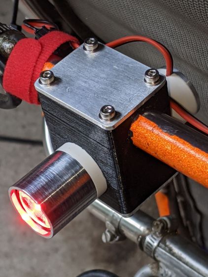
    The front of the light has plenty of clearance from the seat mesh:

    Tour Easy Rear Running Light - installed side view
    Tour Easy Rear Running Light – installed side view

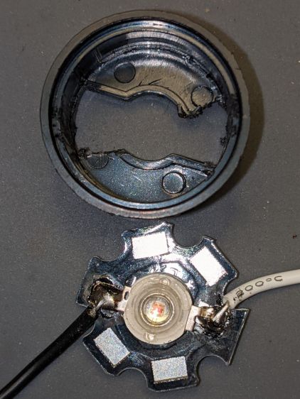
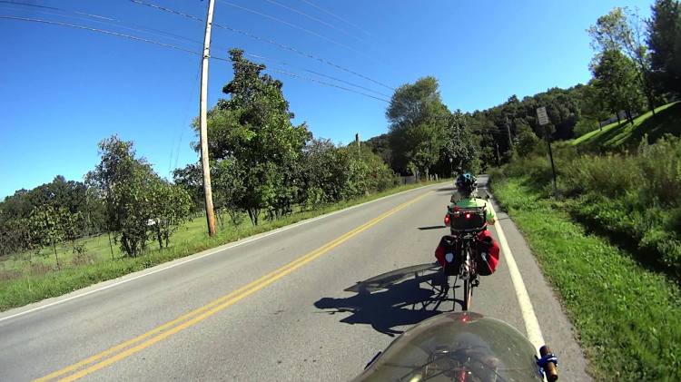
    Out on the road, the 1 W LED appears about as bright as automotive running lights:

    Tour Easy Rear Running Light - tunnel
    Tour Easy Rear Running Light – tunnel

    The blink pattern makes it perfectly visible in sunlight, although I’d prefer somewhat larger optics:

    Tour Easy Rear Running Light - sunlight
    Tour Easy Rear Running Light – sunlight

    In shaded conditions, it’s downright conspicuous:

    Tour Easy Rear Running Light - shade
    Tour Easy Rear Running Light – shade

    At any reasonable distance, the 10° beam covers much of the road behind the bike:

    Tour Easy Rear Running Light - distant
    Tour Easy Rear Running Light – distant

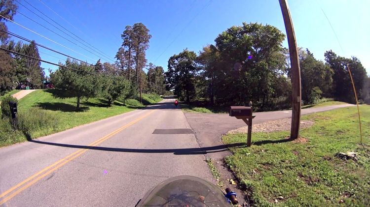
    You may not know what the occulting red light represents, but something ahead is worthy of your attention.

    The Arduino source code producing the two dits:

    // Tour Easy Running Light
    // Ed Nisley - KE4ZNU
    // September 2021
    
    #include <morse.h>
    
    #define PIN_OUTPUT  13
    
    // second param: true = active low output
    LEDMorseSender Morser(PIN_OUTPUT,true,(float)10.0);
    
    void setup()
    {
        Morser.setup();
    
        Morser.setMessage(String("qst de ke4znu "));
        Morser.sendBlocking();
    
    //    Morser.setWPM((float)3.0);
        Morser.setSpeed(75);
        Morser.setMessage(String("i   "));
    }
    
    void loop()
    {
        if (!Morser.continueSending())
            Morser.startSending();
    
    }
    

    Looks good to me, anyhow.

  • Beaver Lodge II

    Beaver Lodge II

    The beaver family living in their pond along the Dutchess Rail Trail near Titusville Rd is doing so well they’ve erected a second lodge:

    Second Beaver Lodge - near Titusville Rd - 2021-09-23
    Second Beaver Lodge – near Titusville Rd – 2021-09-23

    It’s 500 feet (-ish) upstream from the first lodge and seems somewhat smaller, so perhaps it’s for the kids.

  • Why LED Lamps Fail

    Why LED Lamps Fail

    Spotted over a fast food emporium’s parking lot:

    Disemboweled parking lot light
    Disemboweled parking lot light

    It’s hard to be sure, but I think there’s a paper wasp nest around the bundle of wires just above the transformer / ballast / whatever. Perhaps the repair tech departed with the job unfinished?

    As with traffic signals, flashlights, and automotive lighting, the LEDs surely work long after the driver circuitry has given up.

  • Tour Easy Rear Running Light: Circuit Support Plate

    Tour Easy Rear Running Light: Circuit Support Plate

    Building the circuit support plate for the amber front running light was entirely too fiddly:

    1 W LED Running Light - baseplate dry assembly
    1 W LED Running Light – baseplate dry assembly

    This was definitely easier:

    Running Light Circuit Plate - solid model
    Running Light Circuit Plate – solid model

    Two pins fit in the small holes to align it with the LED heatsink, with an M3 stud and brass insert holding it in place:

    Tour Easy Rear Running Light - circuit plate attachment
    Tour Easy Rear Running Light – circuit plate attachment

    The rectangular hole around the insert let me glop urethane adhesive over it to lock it into the plate, with more goop on the screw and pins to unify heatsink and plate.

    The LED wires now emerge from the heatsink on the same side of the plate, simplifying the connections to the MP1584 regulator and current-sense resistor:

    Tour Easy Rear Running Light - regulator wiring
    Tour Easy Rear Running Light – regulator wiring

    The paralleled 5.1 Ω and 3.3 Ω resistors form a 2.0 Ω resistor setting the LED current to 400 mA = 1 W at 2.6 V forward drop. They’re 1 W resistors dissipating a total of 320 mW and get barely warm.

    The resistors and wires are stuck in place with clear adhesive, so things shouldn’t rattle around too much.

    The OpenSCAD source code as a GitHub Gist:

    // Circuit plate for Tour Easy running lights
    // Ed Nisley – KE4ZNU – 2021-09
    /* [Hidden] */
    ThreadThick = 0.25;
    ThreadWidth = 0.40;
    HoleWindage = 0.2;
    Protrusion = 0.1; // make holes end cleanly
    function IntegerMultiple(Size,Unit) = Unit * ceil(Size / Unit);
    ID = 0;
    OD = 1;
    LENGTH = 2;
    inch = 25.4;
    //———————-
    // Dimensions
    // Light case along X axis
    LightID = 23.0;
    WallThick = 2.0;
    Screw = [3.0,6.8,4.0]; // M3 OD=washer, length=nut + washers
    Insert = [3.0,4.2,8.0]; // splined brass insert, minus splines
    InsertOffset = 10.0; // insert from heatsink end
    PinOD = 1.6; // alignment pins
    PinOC = 14.0;
    PinDepth = 5.0;
    Plate = [50.0,LightID,Insert[OD] + 4*ThreadThick]; // overall plate size
    WirePort = [10.0,3.0,2*Plate.z];
    NumSides = 2*3*4;
    //———————-
    // Useful routines
    module PolyCyl(Dia,Height,ForceSides=0) { // based on nophead's polyholes
    Sides = (ForceSides != 0) ? ForceSides : (ceil(Dia) + 2);
    FixDia = Dia / cos(180/Sides);
    cylinder(r=(FixDia + HoleWindage)/2,
    h=Height,
    $fn=Sides);
    }
    // Circuit plate
    module Plate() {
    difference() {
    intersection() {
    cube(Plate,center=true);
    rotate([0,90,0])
    cylinder(d=LightID,h=2*Plate.x,$fn=NumSides,center=true);
    }
    rotate([0,90,0]) rotate(180/6)
    translate([0,0,-Plate.x])
    PolyCyl(Screw[ID],2*Plate.x,6);
    rotate([0,90,0]) rotate(180/6)
    translate([0,0,-Plate.x/2 – Protrusion])
    PolyCyl(Insert[OD],Insert[LENGTH] + InsertOffset + Protrusion,6);
    translate([-Plate.x/2 + InsertOffset + Insert[LENGTH]/2,0,Plate.z/2])
    cube([Insert[LENGTH],Insert[OD],Plate.z],center=true);
    for (j=[-1,1])
    translate([-Plate.x/2,j*PinOC/2,0])
    rotate([0,90,0]) rotate(180/6)
    translate([0,0,-PinDepth])
    PolyCyl(PinOD,2*PinDepth,6);
    for (j=[-1,1])
    translate([0,j*(Plate.y/2 – WirePort.y/2),0])
    cube(WirePort,center=true);
    }
    }
    //- Build it
    Plate();

  • Tour Easy Rear Running Light: LED Lens Assembly

    Tour Easy Rear Running Light: LED Lens Assembly

    Having discovered the need for careful alignment of the LED PCB with the lens, I paid more attention to detail this time around.

    The LEDs arrive soldered to PCBs atop aluminum star heat spreaders, but the one I picked out of the bag looked slightly misaligned. Unsoldering it showed a smear of solder paste had melted across the central pad:

    1 W LED PCB - errant solder
    1 W LED PCB – errant solder

    The LED has a die contact slug on the bottom which, I suppose, could be directly soldered to the spreader. For my simple needs, removing the errant solder, plunking the LED atop a layer of heatsink compound, and resoldering the leads should suffice:

    1 W LED PCB - wire layout
    1 W LED PCB – wire layout

    The LED holder has a pair of slots aligning it with the LED leads on the PCB. The base of the holder sits flush against the PCB, so the wires must attach directly to the LED pads.

    I ran the wires for the amber light through holes close to the pads:

    1 W LED Running Light - heatsink fit
    1 W LED Running Light – heatsink fit

    Which required chewing two passages in the base of the holder:

    1 W LED Running Light - wiring
    1 W LED Running Light – wiring

    It turns out the 5° and 10° lenses are strongly conical and leave plenty of room around the LED to run a wire around the inside of the holder, so I drilled a pair of holes to put both wires on the same side of the circuit plate:

    Tour Easy Rear Running Light - circuit plate attachment
    Tour Easy Rear Running Light – circuit plate attachment

    The holder required minor surgery to let the wire double back on itself over the LED pad:

    1 W LED Holder - wire passage
    1 W LED Holder – wire passage

    The wires thread through two holes drilled in the plastic holder:

    Tour Easy Rear Running Light - clamped LED assembly
    Tour Easy Rear Running Light – clamped LED assembly

    More urethane adhesive glues the PCB to the LED holder, with the clamp applying pressure to the lens to ensure the lens seats properly around the LED. It turned out that worked well and the light has a nicely rounded beam.

    With the optics bonded together, metal-filled JB Weld epoxy attaches the heat spreader to the heatsink with good thermal conductivity:

    Tour Easy Rear Running Light - clamped LED heatsink
    Tour Easy Rear Running Light – clamped LED heatsink

    The LED holder is a slide fit in the heatsink, so the clamps can keep the PCB flat on the bottom of the recess while the epoxy gets a good grip on all parts.

    Now it’s just a matter of wiring everything up!

  • Tour Easy Rear Running Light: LED Heatsink

    Tour Easy Rear Running Light: LED Heatsink

    Because the rear running light will have a higher duty cycle than the front light, I made the (admittedly too small) heatsink slightly longer, with a deeper recess to protect the lens from cargo on the rear rack:

    Tour Easy Rear Running Light - boring LED recess
    Tour Easy Rear Running Light – boring LED recess

    Boring that nice flat bottom is tedious; I must lay in a stock of aluminum tubing to simplify the process.

    Drilling the holes went smoothly:

    Tour Easy Rear Running Light - drilling LED heatsink
    Tour Easy Rear Running Light – drilling LED heatsink

    Those two holes fit a pair of pins aligning the circuit plate, with a screw and brass insert holding it to the heatsink. Scuffing a strip across the aluminum might give the urethane adhesive (you can see uncured globs on the pins) a better grip:

    Tour Easy Rear Running Light - circuit plate attachment
    Tour Easy Rear Running Light – circuit plate attachment

    The screw / insert /pins are glued into the plate to permanently bond it to the heatsink. The screw occupies only half of the insert, with the longer screw from the end cap pulling the whole affair together.

    The two holes on the left pass both LED leads to one side of the circuit plate, where they connect to the current regulator and its sense resistor.

  • Rear Running Light: Too-aggressive Turning

    Rear Running Light: Too-aggressive Turning

    The same lathe fixture and double-sided duct tape trick I used for the amber running light’s end cap should have worked for this one, but only after I re-learned the lesson about taking sissy cuts:

    Tour Easy Rear Running Light - end cap fixture - swirled adhesive
    Tour Easy Rear Running Light – end cap fixture – swirled adhesive

    Yet another snippet of tape and sissy cuts produced a better result:

    Tour Easy Rear Running Light - end cap
    Tour Easy Rear Running Light – end cap

    Protip: when you affix an aluminum disk bandsawed from a scrap of nonstick griddle to a lathe fixture, the adhesive will grip the disk in only one orientation.