Ed Nisley's Blog: Shop notes, electronics, firmware, machinery, 3D printing, laser cuttery, and curiosities. Contents: 100% human thinking, 0% AI slop.
A licensed bird rescuer gave a talk before a showing of Pelican Dreams in Rhinebck and presented some of her patients…
A Red Tailed Hawk with a broken left wing, just out of its bandage:
Red Tailed Hawk – in hand
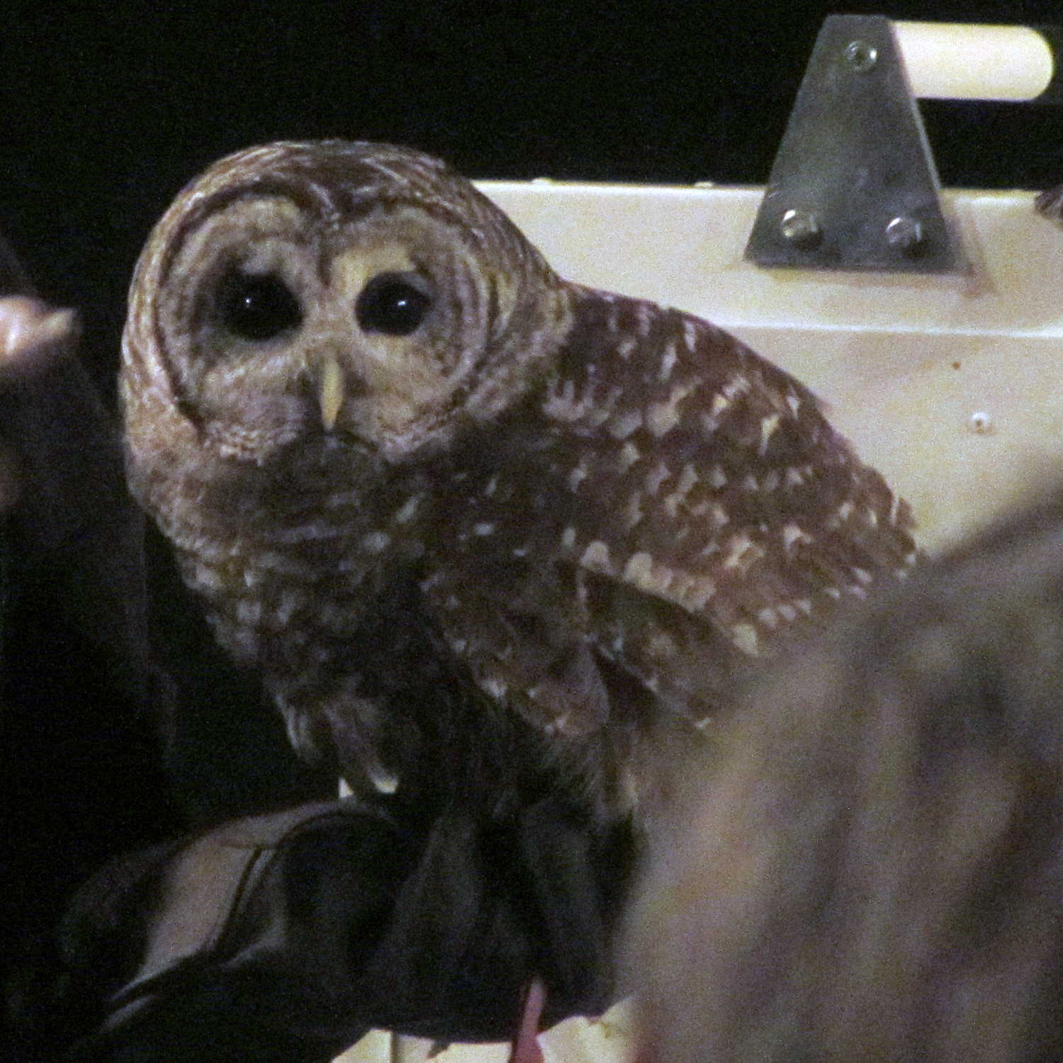
A Barred Owl who, despite having a left eye that no longer dilates, rapidly acquired weapons lock on my camera’s focus assist light:
Barred owl – eye contact
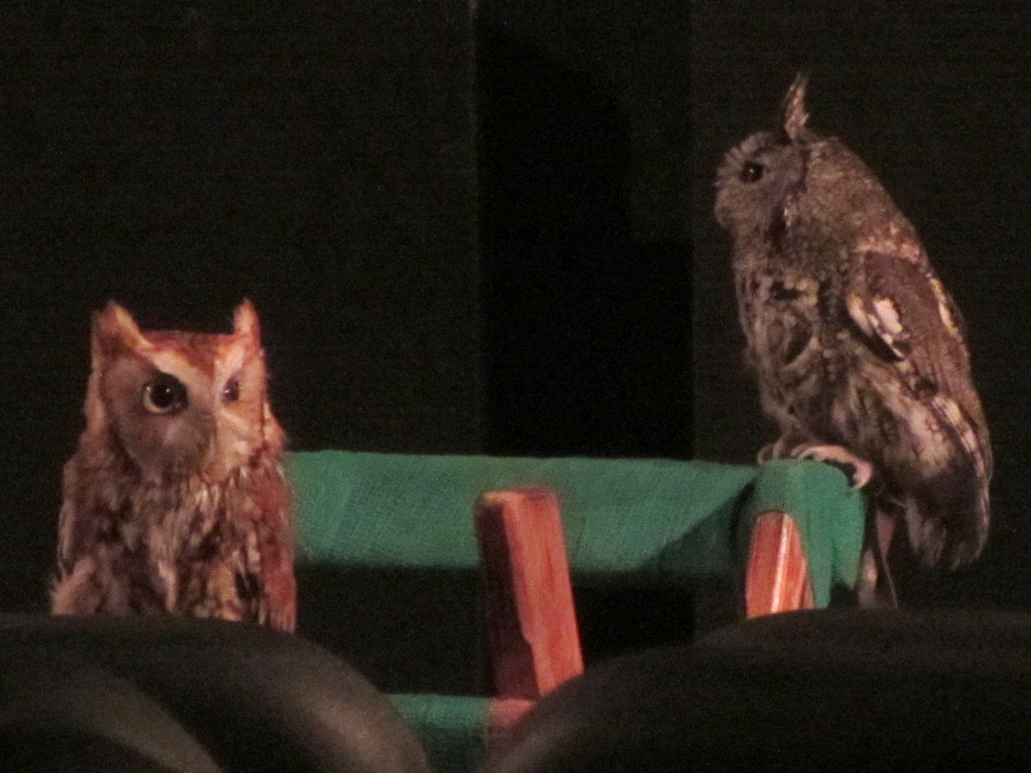
And a pair of insanely cute Screech Owls, both with eye damage, atop their padded perch:
Screech Owls – on stand
Most of her patients arrive after collisions with automobiles; it seems carnivorous birds don’t look both ways before pouncing on prey near the roadside.
Contrary to her impassioned claims, however, wind turbines kill essentially zero birds, at least compared to windows, HV power lines, and cats. Some reports with actual numbers that, obviously, won’t convince anybody who already knows what the results should be:
They’re hanging from the gutters over the patio. The house has six-foot soffits back there and nearly three feet elsewhere, plus the roofers installed rubber sheets along the walls, so we’re not worried about leaks…
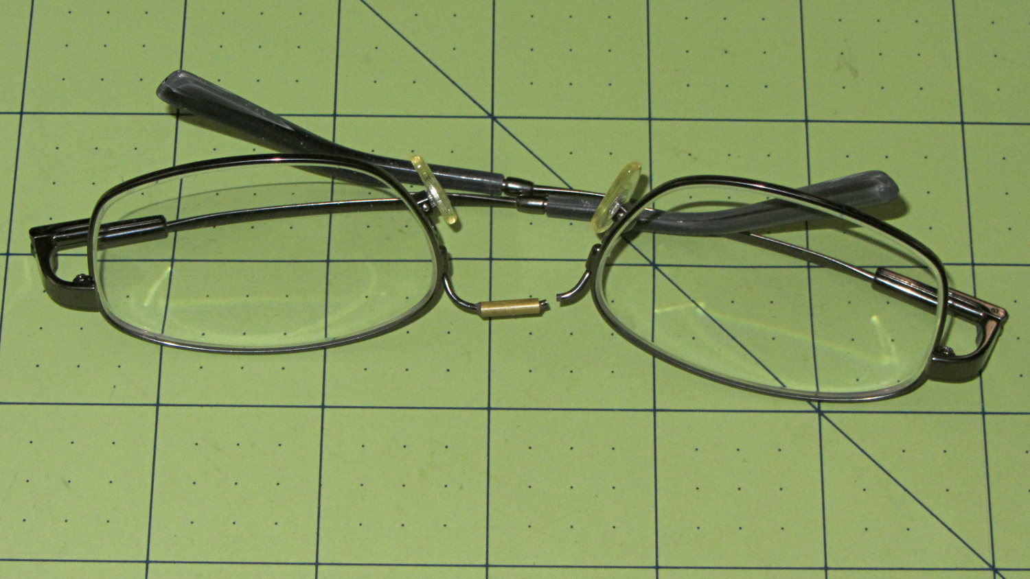
Having repaired these once before, I wasn’t too surprised when this happened:
Eyeglasses – broken nose bridge wire
Evidently the “titanium” has fatigued, because the repair lasted barely nine months.
Rather than try to fix them again, I sent my new prescriptions halfway around the planet and, a bit under two weeks later, had three glasses: normal, computer, and sun. This time, I went with 38 mm tall lenses, a heavier nose bridge, and traditional aviator sunglasses.
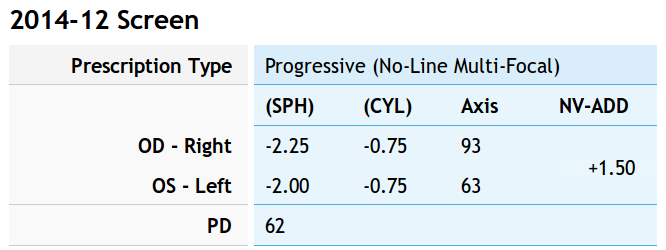
For the record, the regular prescription was:
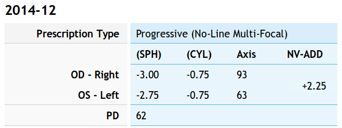
Tweaking that by +0.75 diopter on the sphere puts my far point focus on the monitors across the desk and backing -0.75 diopter from the adder keeps the same near-point reading correction:
Computer prescription – 2014-12
They’re all no-line progressive bifocals made from 1.57 high-index plastic with anti-reflection coating, for a grand total of $135 delivered.
Our Larval Engineer volunteered to convert the lens from a defunct magnifying desk lamp into a hand-held magnifier; there’s more to that story than is relevant here. I bulldozed her into making a solid model of the lens before starting on the hand-holdable design, thus providing a Thing to contemplate while working out the holder details.
That justified excavating a spherometer from the heap to determine the radius of curvature for the lens:
Student Sphereometer on lens
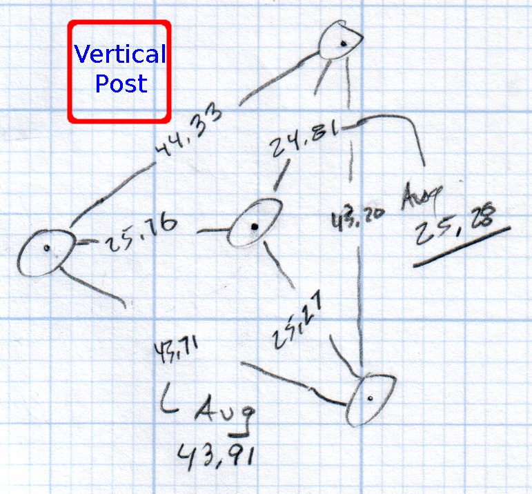
You must know either the average radius / diameter of the pins or the average pin-to-pin distance. We used a quick-and-dirty measurement for the radius, but after things settled down, I used a slightly more rigorous approach. Spotting the pins on carbon paper (!) produced these numbers:
Sphereometer Pin Radii
The vertical scale has hard-metric divisions: 1 mm on the post and 0.01 on the dial. You’d therefore expect the pins to be a hard metric distance apart, but the 25.28 mm average radius suggests a crappy hard-inch layout. It was, of course, a long-ago surplus find without provenance.
The 43.91 mm average pin-to-pin distance works out to a 50.7 mm bolt circle diameter = 25.35 mm radius, which is kinda-sorta close to the 25.28 mm average radius. I suppose averaging the averages would slightly improve things, but …
The vertical distance for the lens in question was 0.90 mm, at least for our purposes. That’s the sagitta, which sounds cool enough to justify this whole exercise right there. It’s 100 mm in diameter and the ground edge is 2.8 mm thick, although the latter is subject to some debate.
Using the BCD, the chord equation applies:
Height m = 0.90 mm
Base c = 50.7 mm
Lens radius r = (m2 + c2/4) / 2m = 357.46 mm
Using the pin-to-pin distance, the spherometer equation applies:
Pin-to-pin a = 43.91 mm
Sagitta h = 0.90 mm
Lens radius R = (h/2) + (a2 / 6h) = 357.50 mm
Close enough, methinks.
Solving the chord equation for the total height of each convex side above the edge:
Base c = 100 mm
Lens radius r = 357.5 mm
Height m = r – sqrt(r2 -c2/4) = 3.5 mm
So the whole lens should be 2 · 3.5 + 2.8 = 9.8 mm thick. It’s actually 10.15 mm, which says they were probably trying for 10.0 mm and I’m measuring the edge thickness wrong.
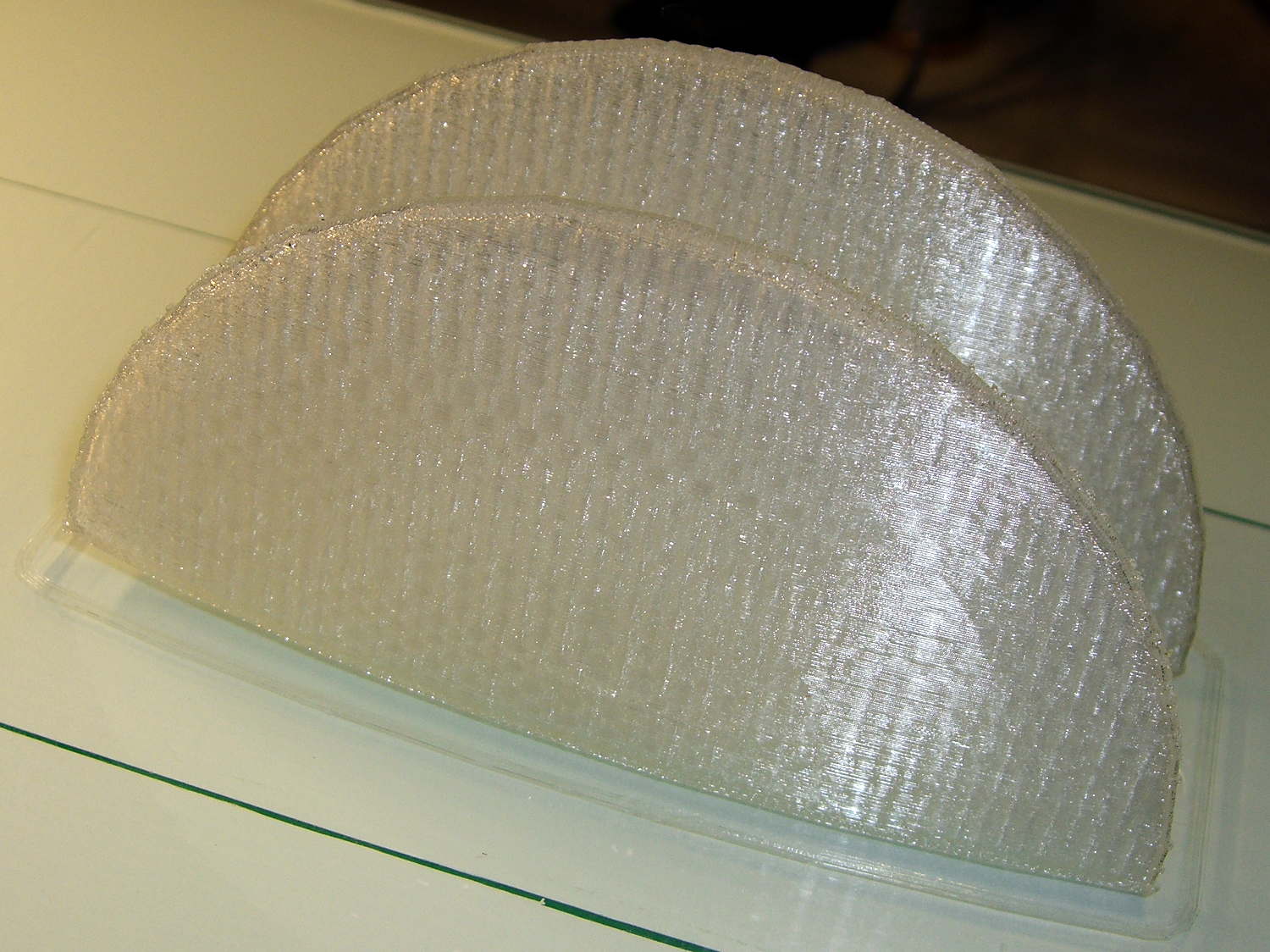
She submitted to all this nonsense with good grace and cooked up an OpenSCAD model that prints the “lens” in two halves:
Printed Lens – halves on platform
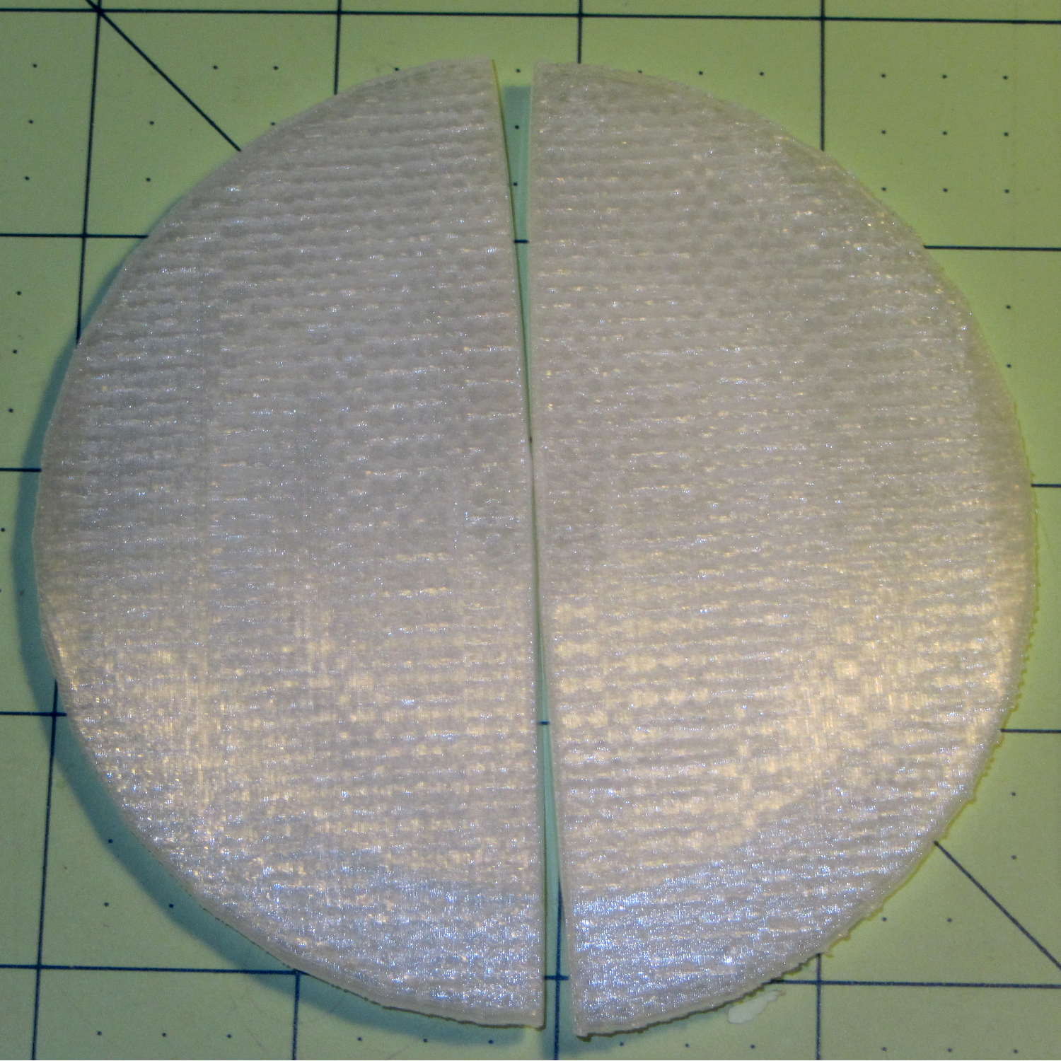
Alas, those thin flanges have too little area on the platform to resist the contraction of the plastic above, so they didn’t fit together very well at all:
Printed Lens – base distortion
We figured a large brim would solve that problem, but then it was time for her to return to the hot, fast core of college life…