The Smell of Molten Projects in the Morning

Ed Nisley's Blog: Shop notes, electronics, firmware, machinery, 3D printing, laser cuttery, and curiosities. Contents: 100% human thinking, 0% AI slop.

Category: Photography & Images

Taking & making images.

  • Anker MicroSD Card Adapter Speeds

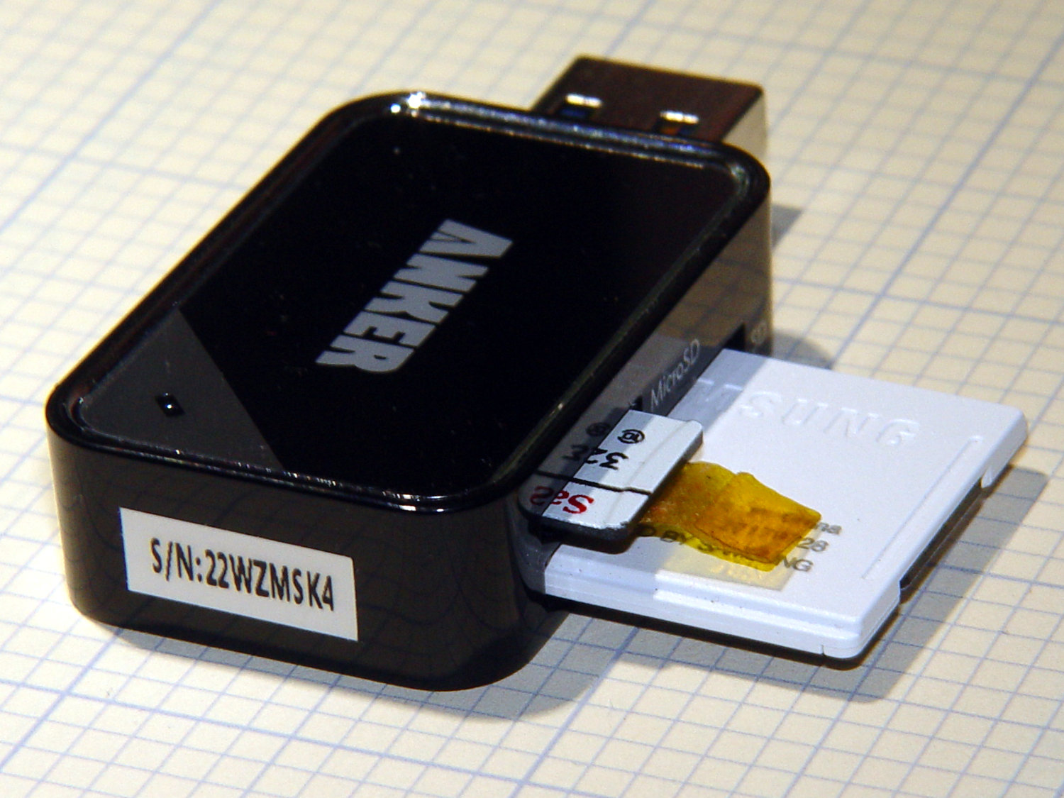
    According to its description, the Anker USB 3.0 card reader can handle both a MicroSD and a standard SD card at once:

    Simultaneously read and write on two cards to save yourself the effort of constant unplugging and re-plugging.

    Which looks like this:

    Anker USB Reader - dual card
    Anker USB Reader – dual card

    After you get used to inserting the SD card downside-up, it fits perfectly. The Kapton tape on the MicroSD card eases extraction from the still finger-dent-less M20 camera mount on the back of my Tour Easy ‘bent.

    Plugged into a USB 3.0 port, my file extractor script chugs along at 25.9 MB/s, taking about 18 minutes to transfer 28 GB of video data.

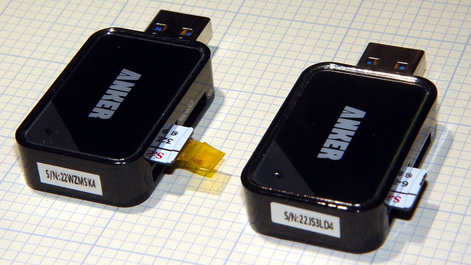
    Splurging another eleven bucks for a second reader produces this setup:

    Anker USB Reader - single card
    Anker USB Reader – single card

    After plugging both readers into adjacent USB 3.0 ports, the script transfers files at 46.6 MB/s and copies 28 GB in 10 minutes.

    So, yes, the reader can handle two cards at once, but at half the speed.

    Not life-changing, but it shows why I like measurements so much …

  • Wyze V2 Camera: Tear-In

    One of my Wyze V2 cameras either arrived with dead IR hardware or failed early on in its tenure here, but it simply didn’t work in night-vision mode: the IR LEDs didn’t turn on and the IR-cut filter didn’t move. Neither the Official Wyze App nor the Xiaomi-Dafang Hacks firmware had any effect, so I expected a (possibly simple) hardware problem.

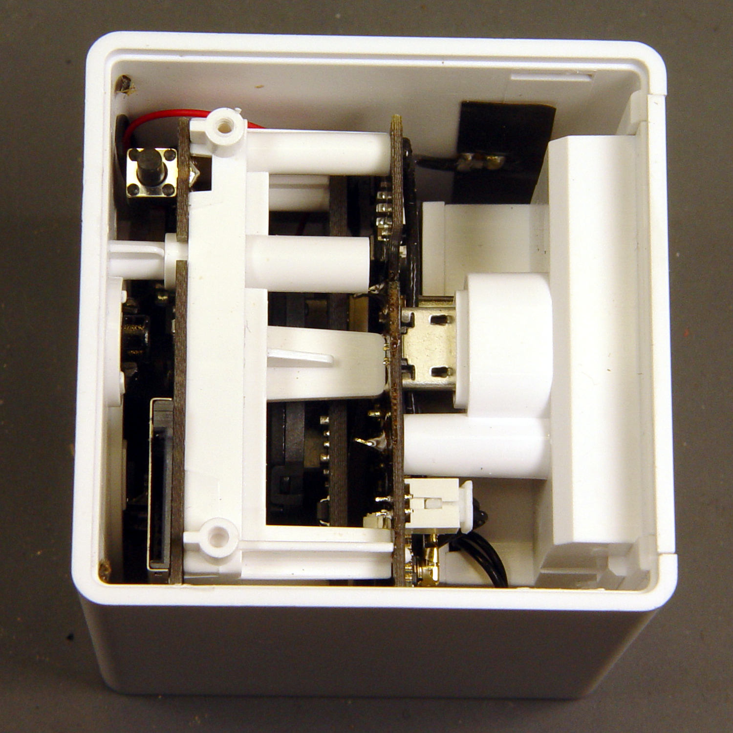
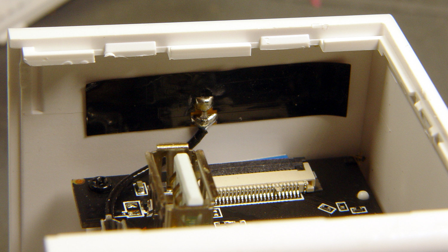
    The first hint of trouble was finding the case had only one of the two screws securing its bottom lid, with the missing screw having never been installed. Removing the single screw and prying a bit popped the lid, revealing the innards:

    Wyze V2 - interior bottom view
    Wyze V2 – interior bottom view

    The rear panel (on the right) comes off after abusing the snaps holding it to the main case:

    Wyze V2 - rear panel snaps
    Wyze V2 – rear panel snaps

    That’s best done with a small, designated Prydriver, rather than a screwdriver to which you have a deep emotional attachment.

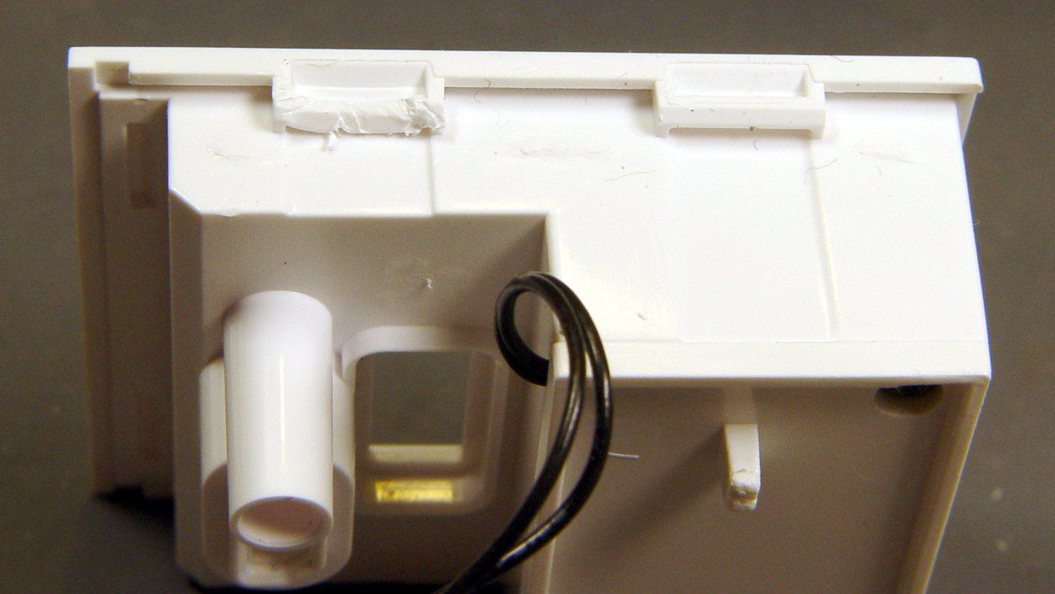
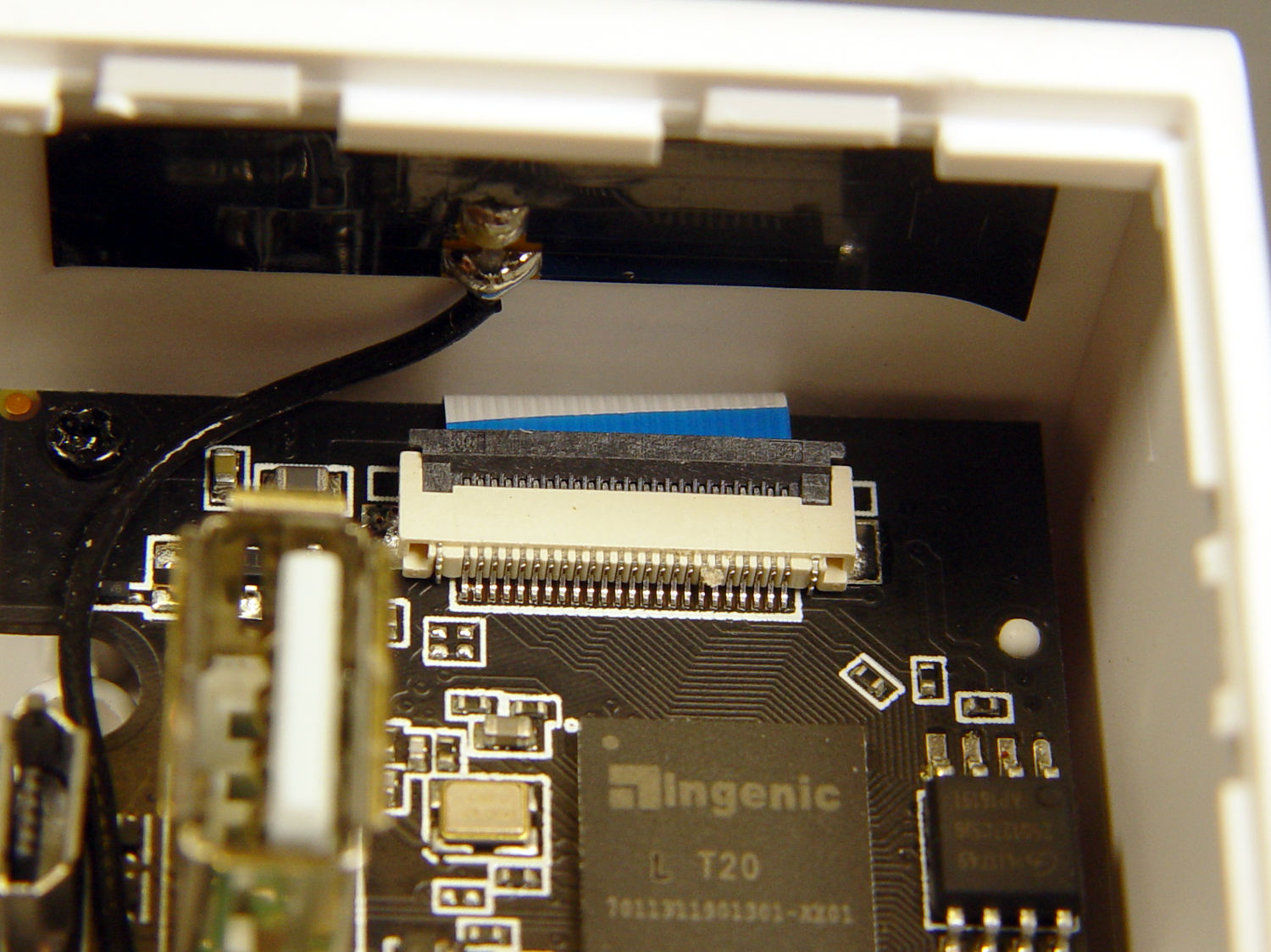
    The corresponding part of the main body shows less abuse:

    Wyze V2 - case snaps - WiFi antenna
    Wyze V2 – case snaps – WiFi antenna

    The black patch is the WiFi antenna, which you must unplug from the top board before going much further.

    The small blue wedge below the antenna gave me hope I’d found the root of the IR problem:

    Wyze V2 - mis-closed ribbon cable
    Wyze V2 – mis-closed ribbon cable

    Everybody has trouble with those delicate ribbon cable socket clamps!

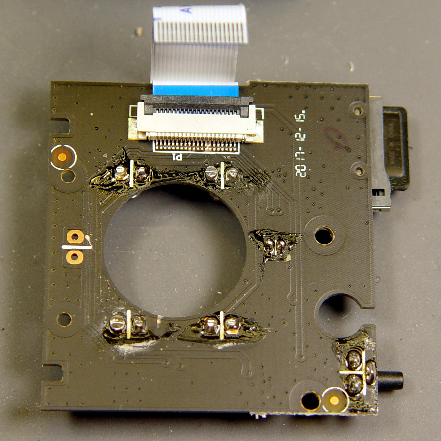
    While I had the case open, I extracted everything and looked it over:

    Wyze V2 - front PCB - LED pin soldering
    Wyze V2 – front PCB – LED pin soldering

    The IR LED soldering left a bit to be desired, so I touched up those joints and washed off most of the flux.

    Alas, the IR hardware still didn’t work with everything stuffed back in the case. There are worse things than having a small daylight-only IP camera, though.

    So it goes …

  • Wyze V2 Cameras: Xiaomi-Dafang Hacks, Round 2

    Another attempt at replacing the Wyze camera firmware went much more smoothly, producing a pair of small cameras with better network manners:

    Wyze Camera hacks - Cam 1 overhead workbench
    Wyze Camera hacks – Cam 1 overhead workbench

    That’s a VLC screen capture from the RTSP stream; obviously, I must up my clutter control game.

    I formatted a 32 GB MicroSD card with a 512 MB partition, which may not be strictly necessary, copied the MicroSD CFW bootloader (as demo.bin, sheesh), and it installed without drama.

    I resized the partition to 32 GB, installed the firmware (per the FAQ) into the root directory, tweaked the configuration files to match my situation, popped it in the camera, plugged the power cable, and It Just Worked™.

    Herewith, a checklist of config directory files requiring tweakage:

    • wpa_supplicant – WiFi SSID and password
    • timezone.conf – America/New_York for us
    • osd.conf – can be tweaked through the Web interface
    • staticip.conf – 192.168.1.11x, as you like
    • resolve.confpihole or router IP, as needed
    • defaultgw.conf – router IP
    • rtspserver.conf – different ports for additional cameras

    It would be possible to have the pihole’s DHCP server assign a fixed IP address to each camera, based on its MAC address, but this way the camera knows who it is right from the start and what it’s supposed to be doing.

    The router isn’t bright enough to route different port numbers on its Internet side to different LAN IP addresses with the same port address, so each camera must stream from a different port number. I don’t plan many world-available video streams, but a friend does enjoy watching the birds during feeder season.

    With the RTSP stream up & running, I flashed the U-Boot bootloader (again, minus drama) and tweaked its uEnv.txt configuration file:

    • Change the memory layout to allow 1920×1080 video
    • ethaddr – set to match hardware MAC address
    • gateway – router IP
    • ipaddr – match the staticip.conf value
    • serverip – router IP (unclear what this does)

    The cameras now produce no objectionable network activity, dramatically down from the Wyze firmware’s desperate attempts to contact various servers, every five minutes, around the clock. I have no way of tracking connections made with direct dotted-quad IP addresses, rather than through the pihole, but … this is a distinct improvement.

  • Sony NP-FM50 Battery Disassembly

    Having won an eBay action for a known-dead Sony DSC-F717 at $0.99 (plus $15 shipping, the seller being no fool), I now have a possibly salvageable camera, a Genuine Sony AC supply, and two more NP-FM50 batteries for about the price of any one of the components.

    One battery arrived stone-cold dead, suggesting the camera had been put away with the battery installed for a very long time and they died companionably. The camera still charges a (good) battery, even though it doesn’t turn on, and perusing the schematics suggests checking the power switch, because it’s always the switch contacts. That’s for another day, though.

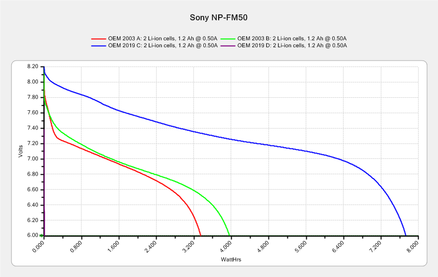
    For the record, the battery status:

    NP-FM50 - 2019-03-30
    NP-FM50 – 2019-03-30

    The red and green traces come from the two batteries I’ve been cycling through the camera since, um, 2003, so they’re getting on in years and correspondingly low in capacity.

    The fourth battery (2019 D, the date showing when it arrived, not its manufacturing date) went from “fully charged” to “dead” in about three seconds with a 500 mA load, producing the nearly invisible purple trace dropping straight down along the Y axis.

    Sawing the dead battery case around its welded joint at a depth of 0.75 mm, then prying with a small chisel, exposed the contents without histrionics:

    Sony NP-FM50 battery - cell label
    Sony NP-FM50 battery – cell label

    Now, there’s a name to conjure with. Turns out Sony sold off its Fukushima battery business a while back, so these must be collectibles. Who knew?

    The lower cell is lifeless, the upper cell may still have some capacity. Three pairs of 18500 lithium cells are on their way, in the expectation of rebuilding the weakest packs.

    After desoldering the battery tab on the right from the PCB, it occurred to me I needed pictures:

    Sony NP-FM50 battery - PCB exposed
    Sony NP-FM50 battery – PCB exposed

    Yeah, that’s a nasty melted spot on the case, due to inept solder-wickage.

    Unsoldering the three tabs closest to the case releases the cells + PCB from confinement:

    Sony NP-FM50 battery - PCB overview
    Sony NP-FM50 battery – PCB overview

    I’m still bemused by battery packs with a microcontroller, even though all lithium packs require serious charge controllers. At least this is an Atmel 8-bitter, rather than 32-bit ARM hotness with, yo, WiFi.

    The cells have shaped tabs which will require some gimmicking to reproduce:

    Sony NP-FM50 battery - cell tabs
    Sony NP-FM50 battery – cell tabs

    Now, if only I could reboot the camera …

  • Desk Lamp Conversion: Photo Light Cold Shoe

    Having recently acquired a pair of photo lights and desirous of eliminating some desktop clutter, I decided this ancient incandescent (!) magnifying desk lamp had outlived its usefulness:

    Desk Lamp - original magnifiying head
    Desk Lamp – original magnifiying head

    The styrene plastic shell isn’t quite so yellowed in real life, but it’s close.

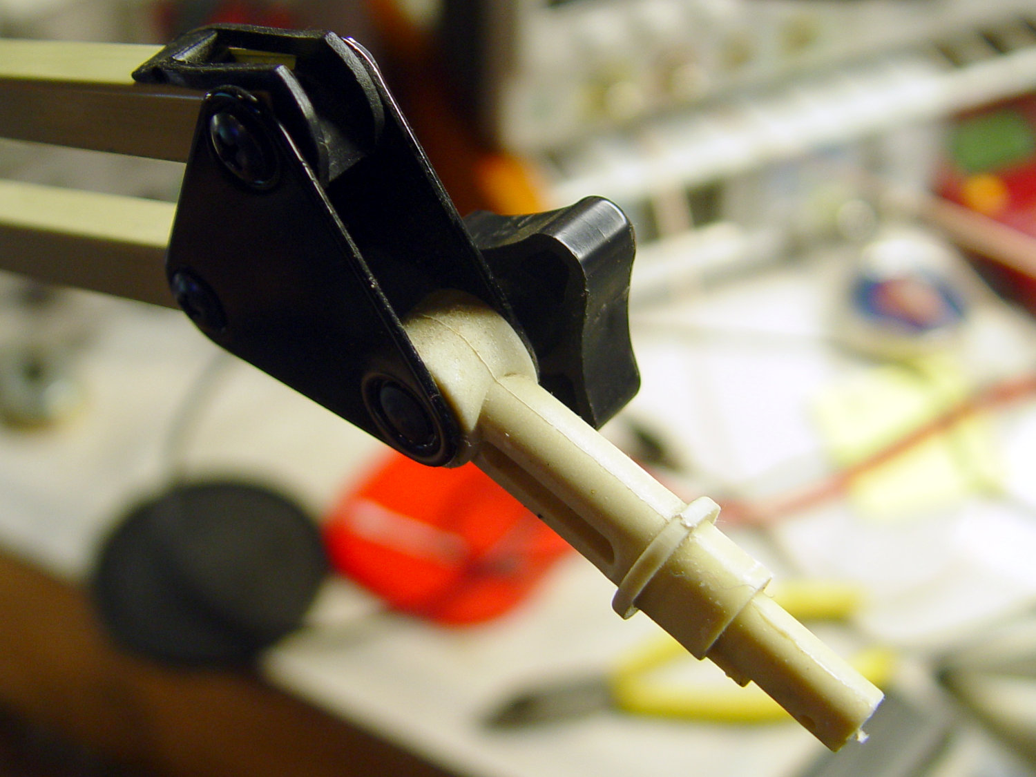
    Stripping off the frippery reveals the tilt stem on the arm:

    Desk Lamp - OEM mount arm
    Desk Lamp – OEM mount arm

    The photo lights have a tilt-pan mount intended for a camera’s cold (or hot) shoe, so I conjured an adapter from the vasty digital deep:

    Photo Light Bracket for Desk Lamp Arm - solid model
    Photo Light Bracket for Desk Lamp Arm – solid model

    Printing with a brim improved platform griptivity:

    Photo Light Bracket for Desk Lamp Arm - Slic3r preview
    Photo Light Bracket for Desk Lamp Arm – Slic3r preview

    Fortunately, the photo lights aren’t very heavy and shouldn’t apply too much stress to the layers across the joint between the stem and the cold shoe. Enlarging the stem perpendicular to the shoe probably didn’t make much difference, but it was easy enough.

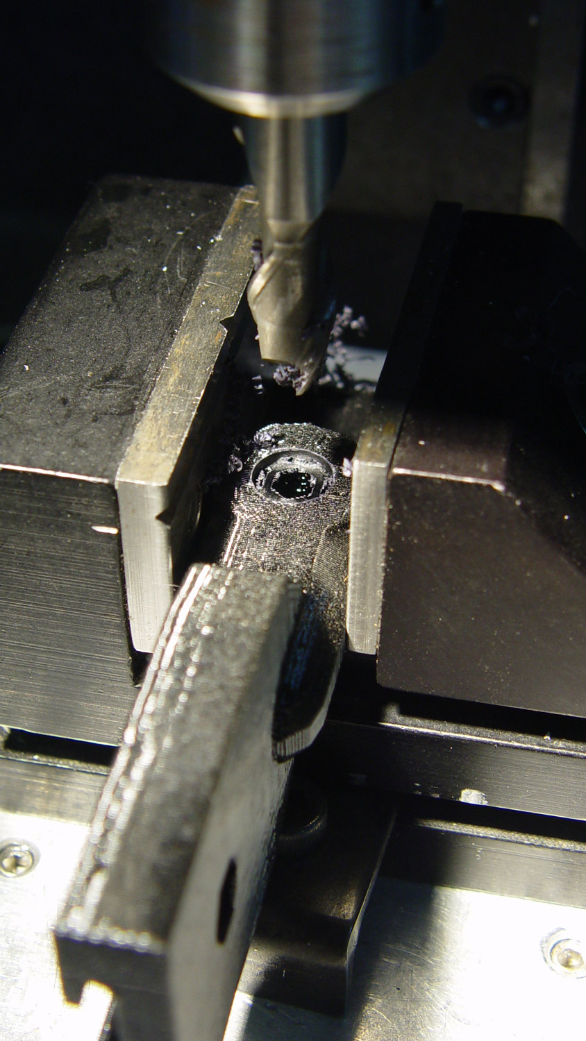
    Of course, you (well, I) always forget a detail in the first solid model, so I had to mill recesses around the screw hole to clear the centering bosses in the metal arm plates:

    Photo Lamp - bracket recess milling
    Photo Lamp – bracket recess milling

    Which let it fit perfectly into the arm:

    Desk Lamp - photo lamp mount installed
    Desk Lamp – photo lamp mount installed

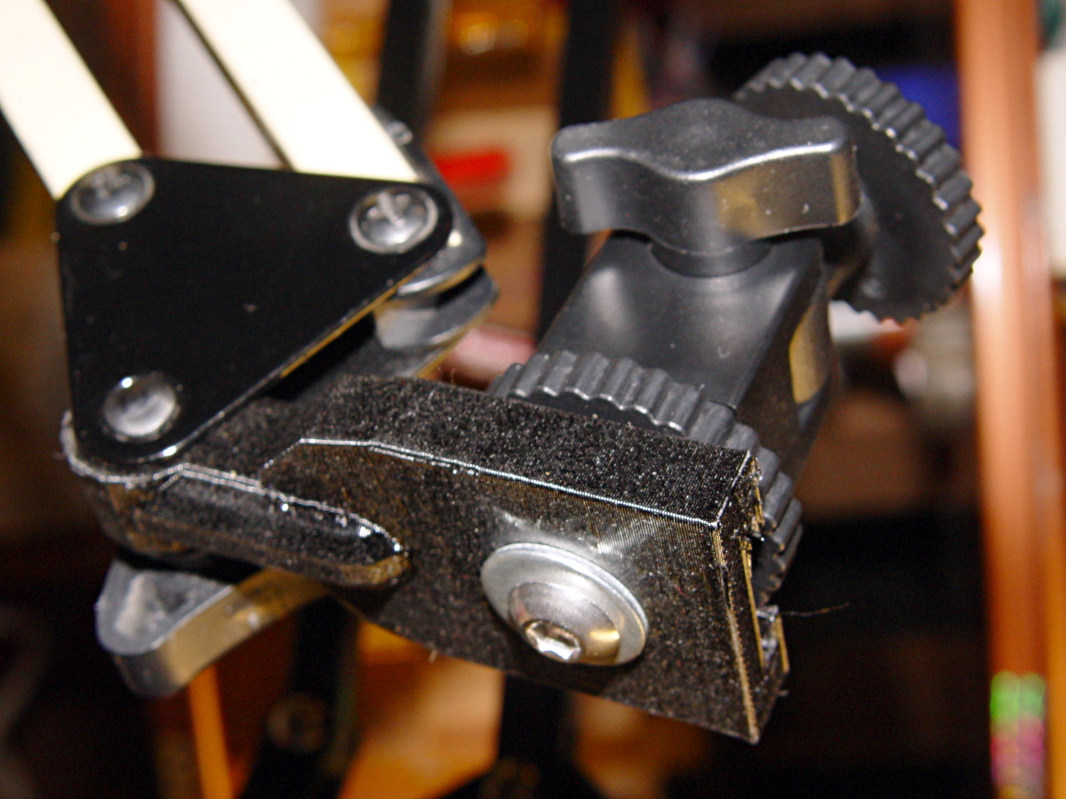
    The grody threads on the upper surface around the end of the slot came from poor bridging across a hexagon, so the new version has a simple and tity flat end. The slot is mostly invisible with the tilt-pan adapter in place, anyway.

    There being no need for a quick-disconnect fitting, a 1/4-20 button head screw locks the adapter in place:

    Photo Lamp - screw detail
    Photo Lamp – screw detail

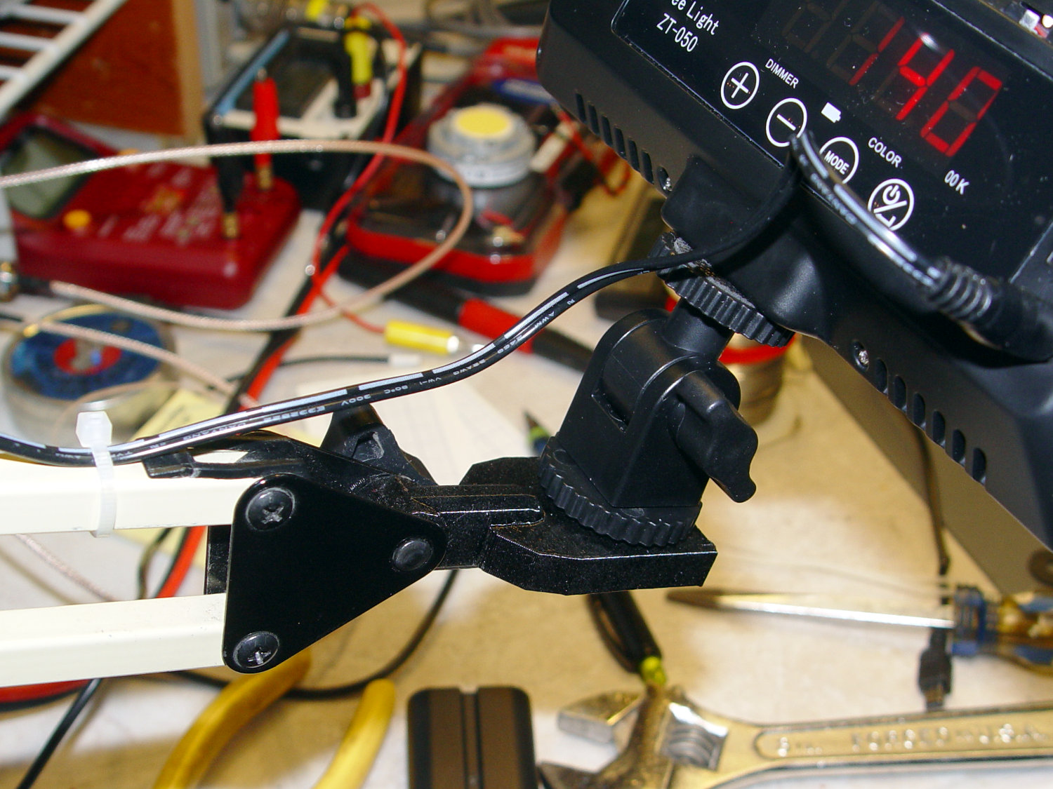
    I stripped the line cord from inside the arm struts and zip-tied the photo lamp’s wall wart cable to the outside:

    Photo Lamp - installed
    Photo Lamp – installed

    And then It Just Works™:

    Photo Lamp - test image
    Photo Lamp – test image

    The lens and its retaining clips now live in the Big Box o’ Optical parts, where it may come in handy some day.

    The OpenSCAD source code as a GitHub Gist:

    // Photo light mount for desk lamp arm
    // Ed Nisley – KE4ZNU
    // 2019-03
    /* [Layout Options] */
    Layout = "Build"; // [Show,Build]
    Part = "Mount"; // [LampArm,ShoeSocket,Mount]
    /* [Extrusion Parameters] */
    ThreadWidth = 0.40;
    ThreadThick = 0.25;
    HoleWindage = 0.2;
    Protrusion = 0.1;
    //—–
    // Dimensions
    /* [Hidden] */
    ID = 0;
    OD = 1;
    LENGTH = 2;
    /* [Dimensions] */
    FrictionDisk = [4.0,16.5,11.0]; // squashed inside desk lamp arm frame
    Divots = [4.0,9.5,0.75]; // recesses for frame alignment bumps
    ArmLength = 30.0; // attached to disk
    ShoeWheelOD = 32.0; // lock wheel on photo lamp
    ShoeBase = [18.5,18.5,2.0] + [HoleWindage,HoleWindage,2*ThreadWidth]; // square base on photo lamp gimbal
    ShoeStem = [6.3,12.0,1.5]; // top slide clearance, ID = 1/4 inch screw
    ShoeBlock = [ShoeWheelOD,ShoeWheelOD,2*(ShoeBase.z + ShoeStem.z)]; // overall shoe block
    NumSides = 3*4;
    //—–
    // Useful routines
    function IntegerMultiple(Size,Unit) = Unit * ceil(Size / Unit);
    module PolyCyl(Dia,Height,ForceSides=0,Center=false) { // based on nophead's polyholes
    Sides = (ForceSides != 0) ? ForceSides : (ceil(Dia) + 2);
    FixDia = Dia / cos(180/Sides);
    cylinder(r=(FixDia + HoleWindage)/2,h=Height,$fn=Sides,center=Center);
    }
    //—–
    // Various Parts
    // Arm captured in disk lamp
    module LampArm() {
    difference() {
    union() {
    cylinder(d=FrictionDisk[OD],h=FrictionDisk[LENGTH],$fn=NumSides,center=true);
    hull()
    for (j=[-1,1])
    translate([0,j*(FrictionDisk[OD]/2 – FrictionDisk[LENGTH]/2),0]) {
    rotate([0,90,0]) rotate(180/NumSides)
    cylinder(d=FrictionDisk[LENGTH]/cos(180/NumSides),h=ArmLength/2,$fn=NumSides);
    translate([ArmLength – FrictionDisk[LENGTH]/2,0,0])
    sphere(d=FrictionDisk[LENGTH],$fn=NumSides);
    }
    }
    rotate(180/6) {
    PolyCyl(FrictionDisk[ID],FrictionDisk[LENGTH] + 2*Protrusion,6,Center=true);
    for (k=[-1,1])
    translate([0,0,k*(FrictionDisk[LENGTH]/2 – Divots[LENGTH]/2)])
    PolyCyl(Divots[OD],Divots[LENGTH] + Protrusion,6,Center=true);
    }
    }
    }
    // Basic hot shoe socket
    module ShoeSocket() {
    difference() {
    union() {
    cube(ShoeBlock,center=true); // overall blocky retainer
    translate([-ShoeBlock.x/2,0,0])
    cylinder(d=ShoeBlock.x,h=ShoeBlock.z,$fn=NumSides,center=true);
    }
    translate([0,0,-2*ShoeBlock.z]) // screw hole throughout
    rotate(180/6)
    PolyCyl(ShoeStem[ID],4*ShoeBlock.z,6);
    translate([0,0,ShoeBase.z/2]) // base slot under pillar
    cube([ShoeBase.x,ShoeBase.y,ShoeBase.z],center=true);
    translate([ShoeBase.x/2,0,ShoeBase.z/2]) // base slot opening
    cube([ShoeBase.x,ShoeBase.y,ShoeBase.z],center=true);
    translate([ShoeStem[OD]/2,0,ShoeBase.z/2 + ShoeStem[LENGTH]]) // stem slot
    cube([2*ShoeStem[OD],ShoeStem[OD],2*ShoeStem[LENGTH]],center=true);
    }
    }
    // Stick parts together
    module Mount() {
    rotate([90,0,0])
    LampArm();
    translate([ArmLength + ShoeBlock.x/2 – Protrusion,0,0])
    ShoeSocket();
    }
    //—–
    // Build things
    if (Layout == "Build") {
    rotate([0,90,0])
    translate([-(ArmLength + ShoeBlock.x),0,0])
    Mount();
    }
    if (Layout == "Show")
    if (Part == "LampArm")
    LampArm();
    else if (Part == "ShoeSocket")
    ShoeSocket();
    else if (Part == "Mount")
    Mount();

    The original dimension doodles, made before I removed the stem and discovered the recesses around the screw hole:

    Photo Light - Desk Lamp Arm Dimensions
    Photo Light – Desk Lamp Arm Dimensions
  • Pileated Woodpecker At Work

    A loud rat-a-tat-a-tat drew our attention to a Pileated Woodpecker excavating a tree along Rt 376:

    Pileated woodpecker
    Pileated woodpecker

    Pileated woodpeckers sculpt their holes with great care, often inspecting their work for smoothness and, perhaps, lunch:

    Pileated woodpecker - exploring hole
    Pileated woodpecker – exploring hole

    Those holes go deep enough inside the tree to serve as shelters for smaller birds during storms.

    We occasionally see and hear them, as well as their smaller relatives, remodeling trees around the house. Good hunting!

    Taken with the Pixel XL zoomed all the way tight, cropped and sharpened a smidge.

  • Sony DSC-F717 Memory Stick Socket Cable Re-Rework

    Once again, the Memory Stick socket cable in my trusty DSC-F717 camera became erratic, leading to continuous C:13:01 “format error” crashes, so I tore it apart. Proceed as before, until the camera carcass disgorges the socket:

    DSC-F717 - Memory Stick socket - side latches
    DSC-F717 – Memory Stick socket – side latches

    Gently pry the metal cover outward to clear the latches along the sides:

    DSC-F717 - Memory Stick socket cover latches
    DSC-F717 – Memory Stick socket cover latches

    The cover remains held in place by two tabs inside the holes on either side of the Memory Stick contacts, one of which is already free in the previous photo:

    DSC-F717 - Memory Stick socket - bottom
    DSC-F717 – Memory Stick socket – bottom

    The small spring on the left ejects the Memory Stick and will, if suitably provoked, launch itself across the bench. Be prepared!

    Use a pointy instrument to ease those tabs away from their latches and pop the top:

    DSC-F717 - opened Memory Stick socket
    DSC-F717 – opened Memory Stick socket

    I cleaned the contacts, not that they appeared particularly filthy, gently bent them upward by three micro-smidgens to apply a bit more pressure to the card’s contacts, and reassembled the socket in reverse order.

    I put a strip of Kapton tape on the back of the cable termination paddle (shown here during the previous repair) to ensure a snug fit:

    DSC-F717 Memory Stick socket - cable entry
    DSC-F717 Memory Stick socket – cable entry

    Unfortunately, I snapped off a locking tab on one of the ribbon cable connections to the main board:

    DSC-F717 - broken cable clamp
    DSC-F717 – broken cable clamp

    The cable threads through the middle of the clamp, which then slides into the socket and applies pressure to the contacts through the cable: no clamp, no pressure, no good.

    For lack of anything smarter, I tamped the clamp into the socket and applied a strip of Kapton tape to maintain everything in more-or-less the right position:

    DSC-F717 - tape-anchored cable
    DSC-F717 – tape-anchored cable

    Definitely unpretty, but better than nothing. While I was in there, I reinforced the other connections with similar clamps.

    Reassemble the camera in reverse order and it’s all good:

    DSC-F717 - repaired - first image
    DSC-F717 – repaired – first image

    It probably won’t last another decade, but ya never know …