So this device showed up in an envelope with a letter telling us we’d won a contest if, of course, the number on the device matched the number in the letter:
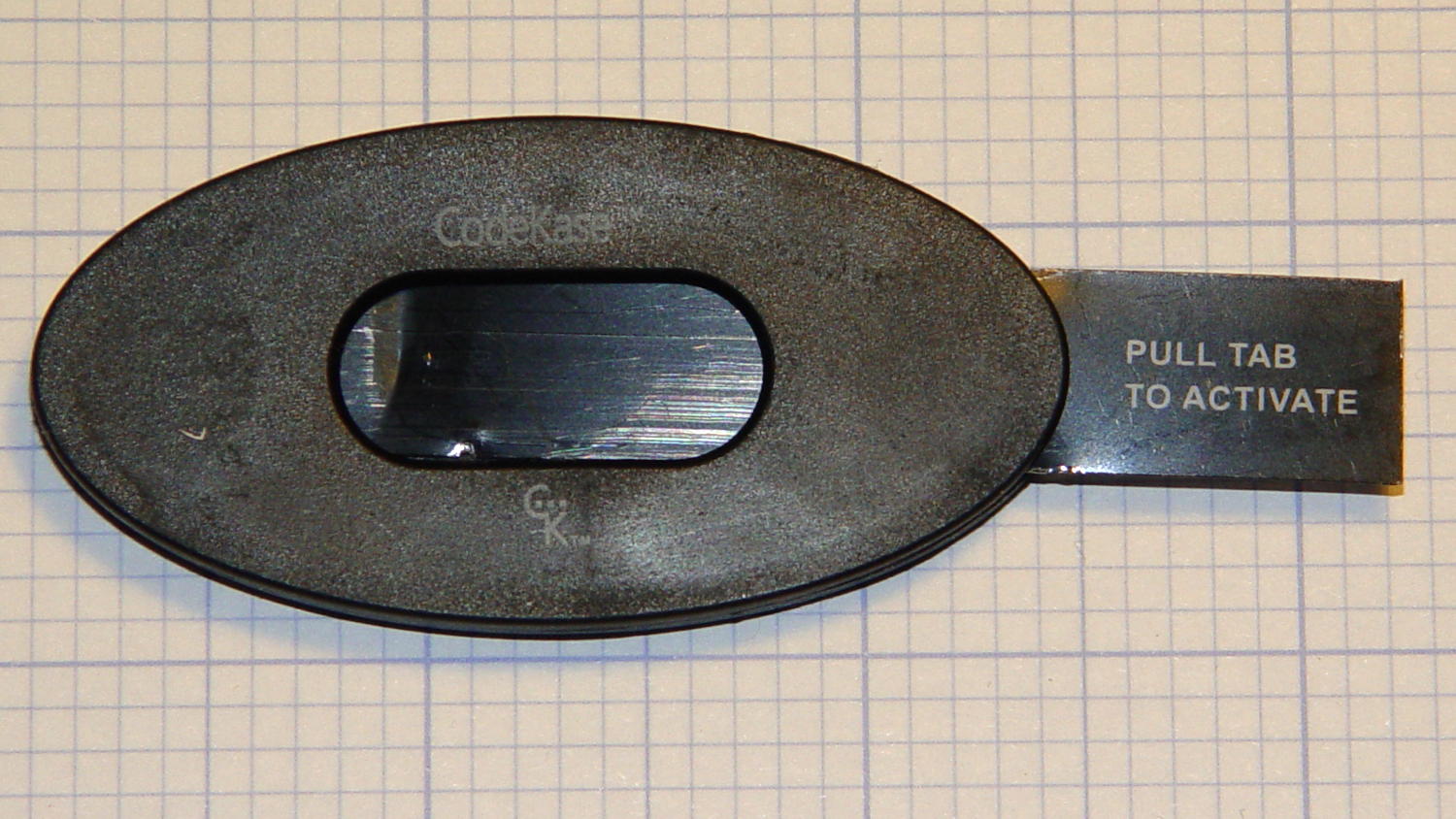
I wonder if anybody else had second thoughts about pulling what’s obviously an insulating sheet holding two contacts apart? In this day and age, getting the victim to blow his own fingers off probably counts as a win.
Maybe it comes from having read The White Plague at an impressionable age. Who could resist getting a Nice Thing in the mail?
The number matched, of course, but the letter’s finer print said the prize would be one of:
- A new car of some sort
- A flat screen TV
- A cheap electronic trinket
- A three-day / two night vacation
In order to claim your prize, you had to call an 800 number. The much finer print revealed the odds of winning the first three of those prizes was somewhere around 300,000:1. “Winning” the vacation was essentially a slam-dunk proposition, of course, and probably tells you everything you need to know about the course of the phone call.
It’s apparently economical to send out this much hardware to reel in new “customers”:

Using the metal disk from a membrane switch as a spring to push the coin cell against the contact wires is a nice touch. This is apparently the optimized version that uses a single lithium cell in place of two alkaline buttons; the cell “socket” on the other end consists of vestigial lumps.
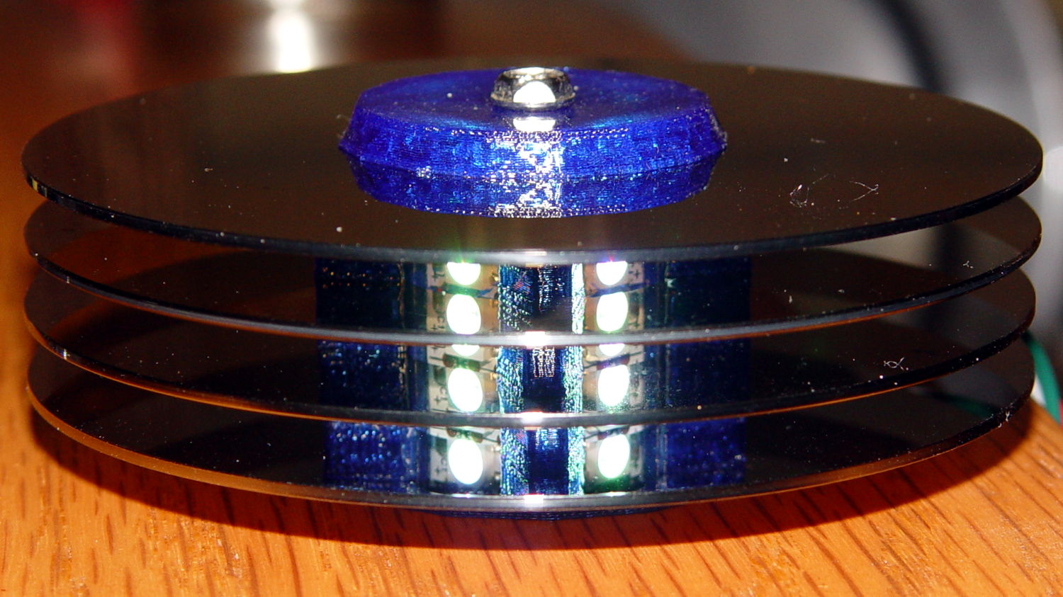
I harvested the lithium cell and the blue LED, of course…
More about CodeKase, direct from the source. I like “Step Five: Recycle Your CodeKase”…