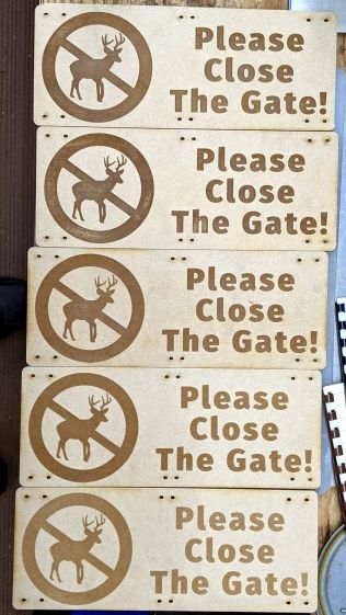
Making signs for the gates surrounding the Vassar Community Gardens provided an opportunity to test laser engraving power on MDF:
The alert reader will observe MDF is totally the wrong material for outdoor signage, which is correct. I’ll be producing different signs as these disintegrate, with an emphasis on engraving different materials and applying different finishes along the way; nobody pays attention to signs, anyway.
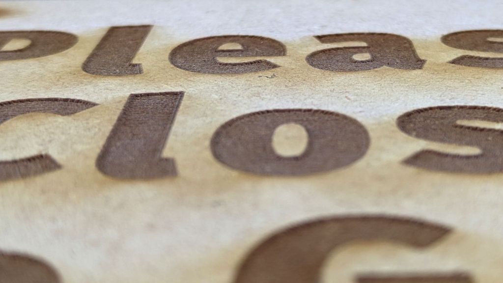
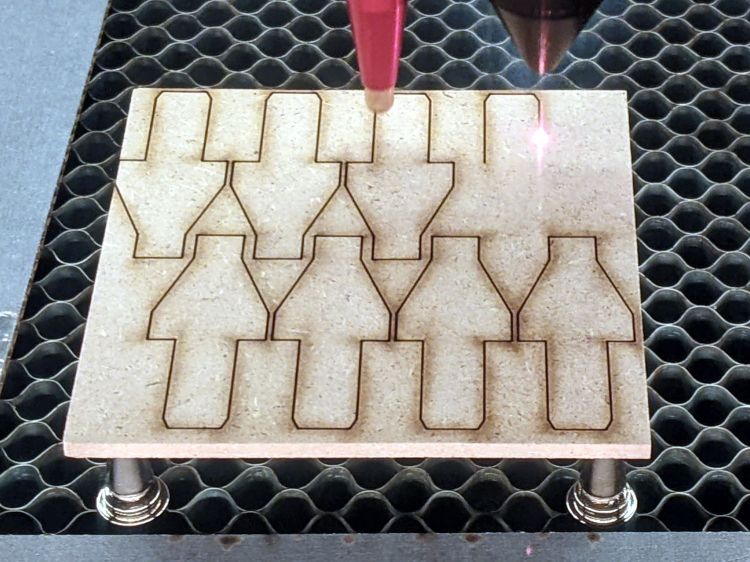
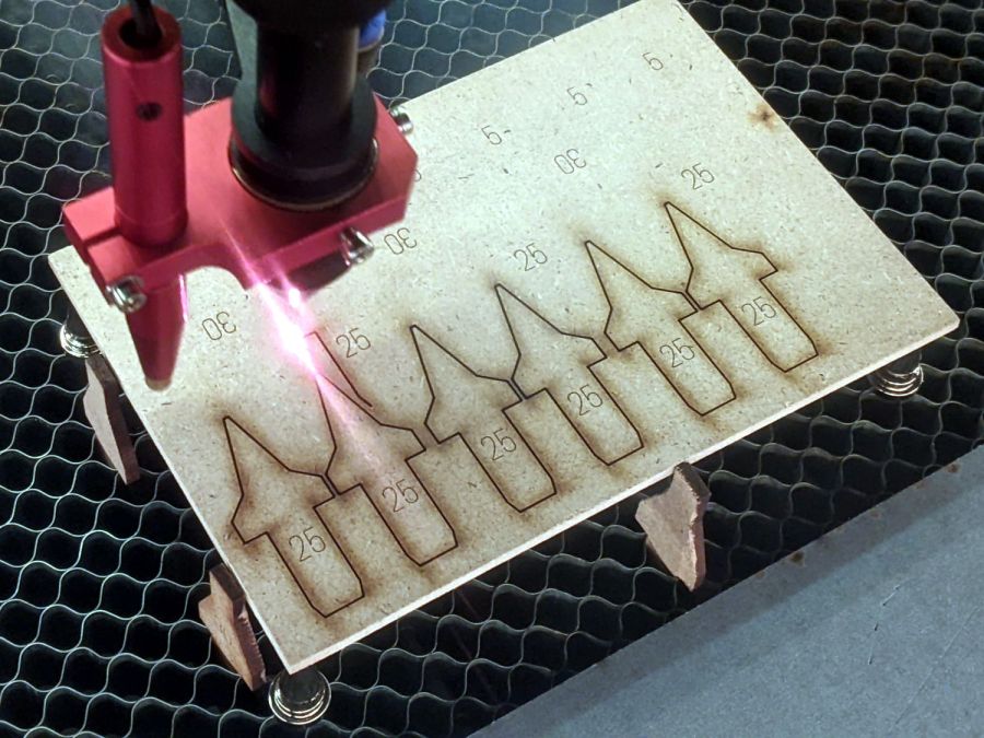
With that in mind, the engraving power ranged from 60% on the top sign to 20% at the bottom, perhaps 40 W to 10 W, with a scanning speed of 500 mm/s. The highest power punched the engraving about 0.5 mm below the surface:

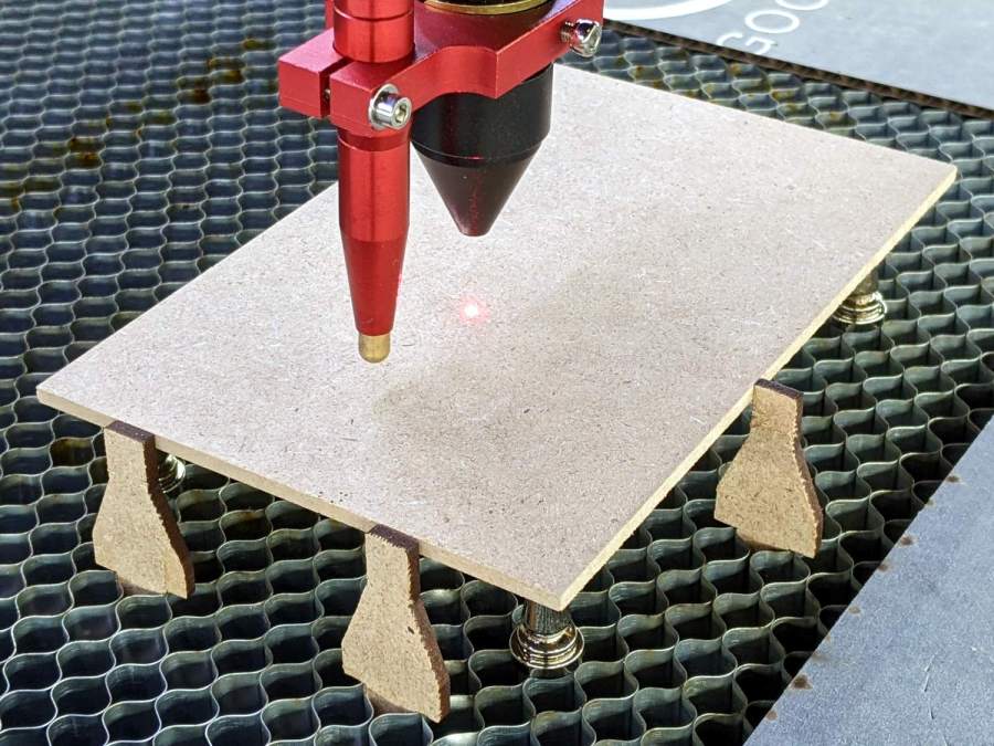
They’re engraved on both sides, so those MDF locating pins came in handy:
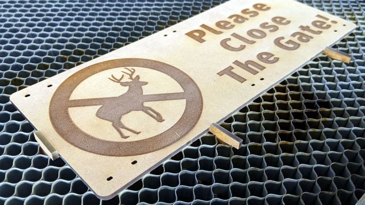
Alignment was obviously not critical.
Slathering the signs with polyurethane finish rated for indoor use improved the contrast on the deeper engraving:
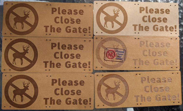
The bare sign (upper right) went on a distant / locked / rarely-used vehicle gate, where it will serve as an exposure control while turning into mush.
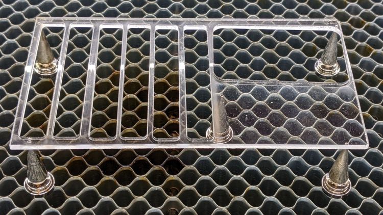
The small acrylic sign, a prototype for amusement value, clearly shows the need for offset correction at such high scan speeds:

The MDF signs fit inside one vertical space of the “four inch” wire mesh on the gates, where they rest on the lower wire, and span three wires horizontally, so I could attempt to control the inevitable warping:
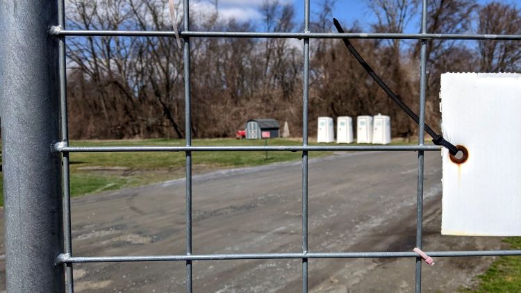
The mesh wire spacing is not mmmm a closely controlled manufacturing parameter, so the next iteration must be a few millimeters shorter to fit the smallest openings.


