Ed Nisley's Blog: Shop notes, electronics, firmware, machinery, 3D printing, laser cuttery, and curiosities. Contents: 100% human thinking, 0% AI slop.
While I was puttering around inside the laser cabinet, I figured it was time to check the mirrors for cleanliness. The first two mirrors looked fine, but Mirror 3 needed help:
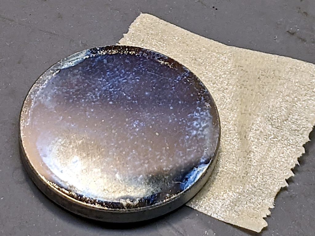
A first pass with an optical wipe removed most of the crud:
OMTech 60W laser mirror 3 cleaning – during
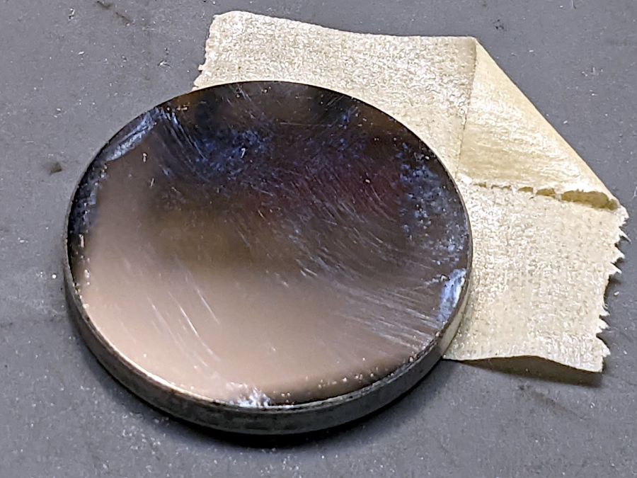
Gentle touch-up with a little more isopropyl alcohol cleared the rest:
OMTech 60W laser mirror 3 cleaning – after
The focus lens required similar attention, but there is no way to get meaningful pictures of a transparent lens.
Realigning the mirrors went well (top before, middle during, lower after):
Beam Alignment Targets- 2022-08-06
The diagonal results at Mirror 3 show the XY axes aren’t quite square, but AFAICT it’s close enough. The rightmost tape shows good beam centering in the nozzle and the Focus target shows excellent Z alignment over about 50 mm of travel.
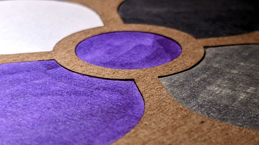
A long-forgotten pad of Art Paper in assorted colors came to the surface:
Layered Coaster – tweaked
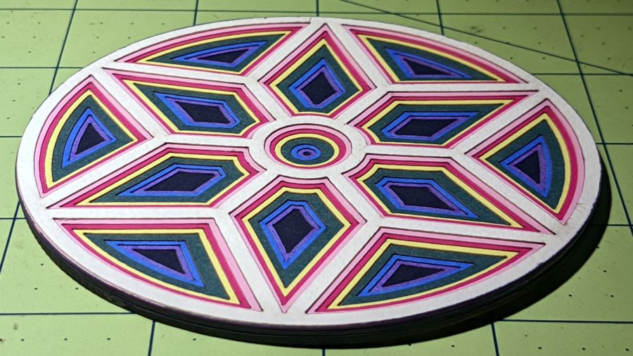
An angled view shows off the layering a little better:
Layered coaster – side view
Done manually with LightBurn’s Offset tool: shrink the frame’s interior openings (which lie outside the frame) by 1 mm per step, then cut each shape into a different color. The black layer is a complete disk, stuck atop a plain chipboard disk for stiffening.
In the cold light of day, I think I offset the green layer by 2 mm.
It’s not a particularly useful coaster, because you want a flat surface under your drink, but it does look pretty. Nowhere close to that good, but I like it.
The next time around, I’ll automate the process by stepping the sash width by 1 mm and saving each SVG image separately.
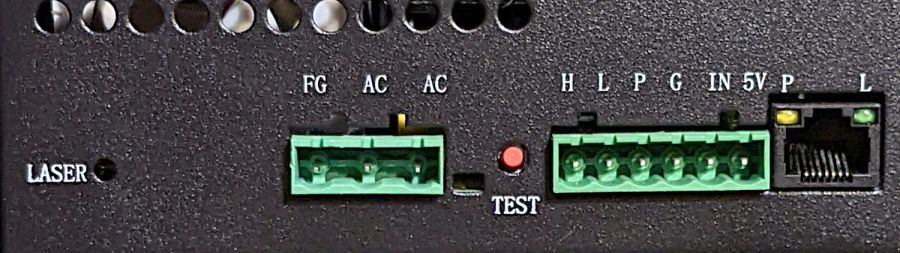
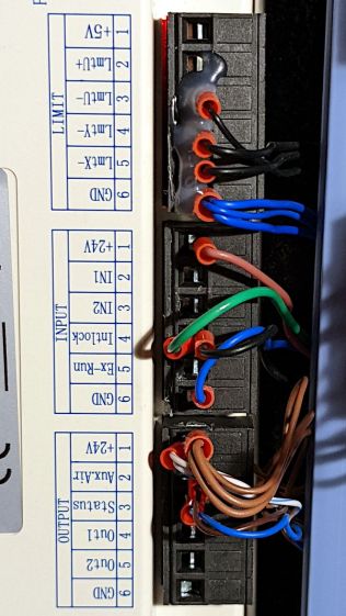
AFAICT, that’s the default layout for all similar power supplies.
The H and L pins are the High- and Low-active enable inputs that, when it’s working right, control the laser output. The KT332 controller (and, most likely, all RuiDa controllers) produce a low-active output, so you just wire the controller’s output to the L input and you’re done.
That was the original failure that got me to this point: the power supply ignored its L input and turned the beam on at whatever power the PWM signal on the IN terminal called for. Having that happen was surprising, having it happen with the cabinet lid open was … disturbing.
The P input is intended for the Water Protect signal from the flow sensor on the laser cooling plumbing. When the water is flowing, the IN terminal will be low and the power supply will pay attention to the L input.
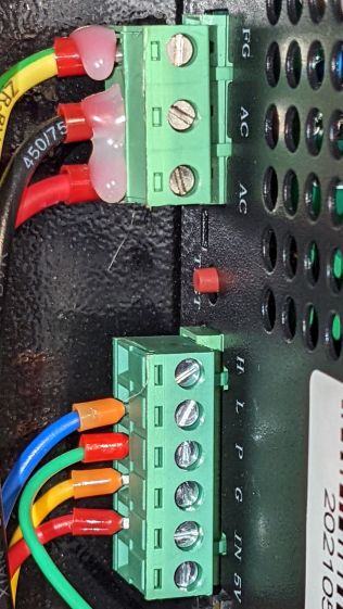
The power supply arrived with a jumper between the P input and the G ground / common terminal:
OMTech 60W HV power supply – Water Protect jumper
The jumper holds the P input low = active, meaning the power supply thinks the water is always flowing.
It turns out that the Water Protect signal goes only to the controller. When it’s inactive = no water flowing, the controller will refuse to fire the laser and also sound an alarm. Running the signal directly to the power supply would result in a puzzling failure-to-fire with no diagnostic from the controller.
I removed that jumper and added a (green) wire from the Lid Interlock signal at the controller:
OMTech KT332 controller – Lid Interlock input – added wire
To the power supply’s P input:
OMTech 60W HV power supply – Water Protect as Lid Interlock
In principle, if this power supply fails the same way as the previous one (with its L input always active), then at least it won’t fire with the lid up.
Believing that may display a childish naivety, but at least the thing seems marginally safer than it was before.
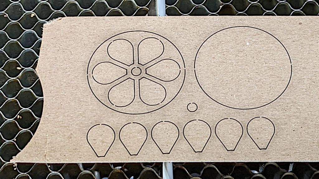
That’s the top and bottom of a 40 mm diameter chipboard dollhouse coaster. I made it that small to emphasize the laser kerf: a scant 3 mm across the scorched path on the top and barely 1 mm wide through the bottom, with tabs holding the pieces in place.
The SVG images include the overall frame, as seen above, and the separate pieces for kerf compensation:
Miniature Coaster – on platform
Embiggening the pieces by 0.15 mm all around produces a very snug fit:
Chipboard Kerfs – compensated – composite
I must eventually try that trick with wood, but at least I managed to get the process down without wasting entire veneer sheets.
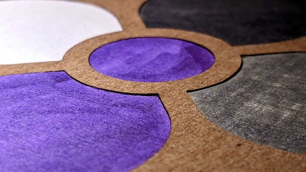
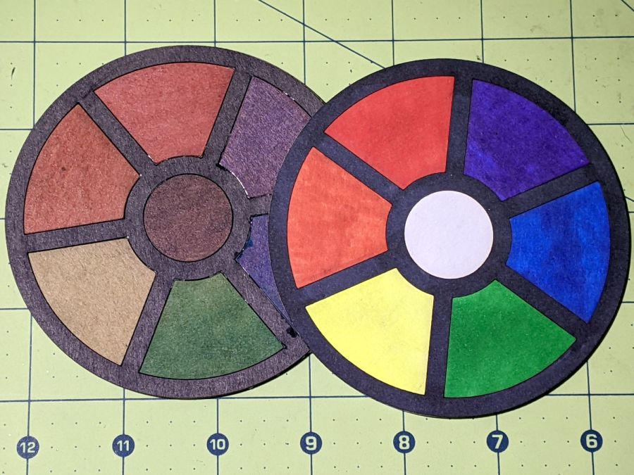
Yes, there really is a difference between 35 mil and 57 mil chipboard:
Chipboard coaster – 35 mil white vs 57 mil kraft
The thinner leaves (0.92 mm) have one delicate white surface that presents much better color when scribbled with fat-tip colored markers. The thicker frame (1.45 mm) is ordinary kraft chipboard which seems much more durable and looks terrible when colored.
Although it may be a case of gilding the dandelion, a durable kraft frame sets off the petal colors and, being slightly thicker, may also protect them from immediate destruction by sweaty drinks.
We’re talking artsy coasters here, not cheap disposable junk. Right?
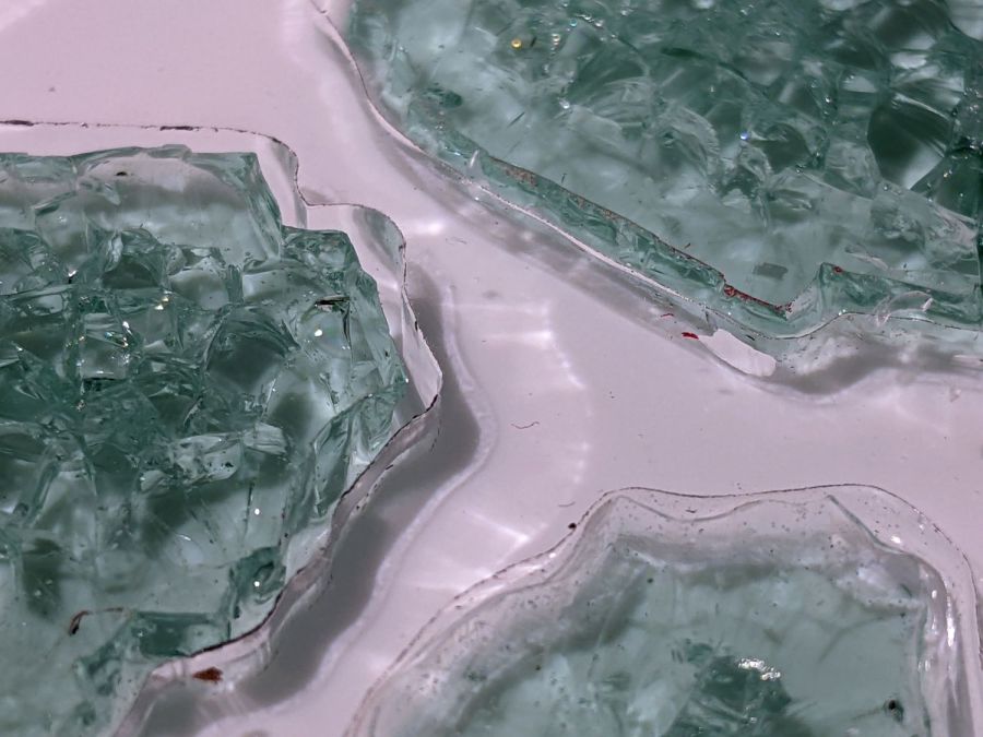
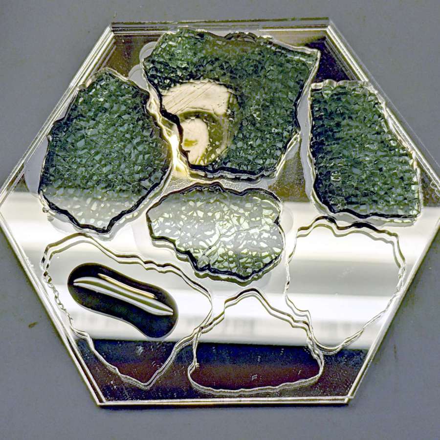
So I assembled a coaster from shattered glass in a clear surround with black epoxy atop a mirror base:
Smashed Glass Coaster 2 – mid-layer glass pour
Each fragment sits on a blob of black epoxy that eventually oozed out to fill the gap between the mirror and the transparent layer. You can see the oozing start around the two fragments in the upper left.
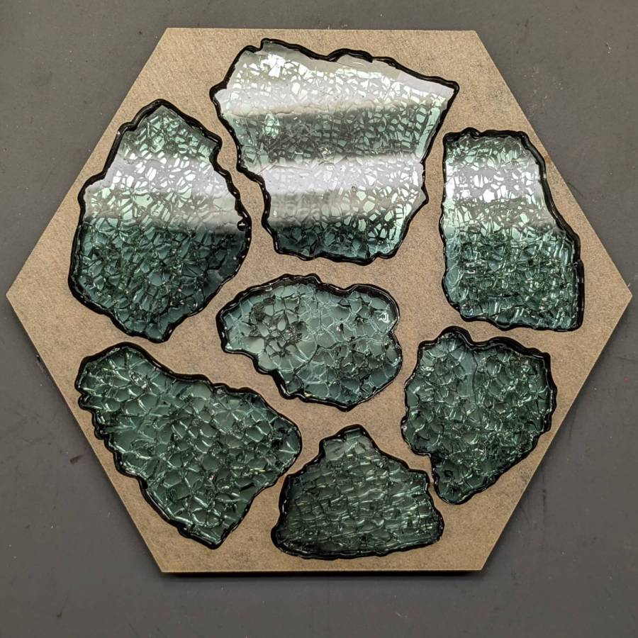
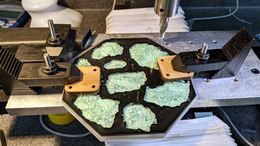
A top layer of black acrylic sits flush with the upper surface of the glass, seen here with the protective paper in place before pouring black epoxy into the gap around the perimeter of each fragment:
Smashed Glass Coaster 2 – masked top
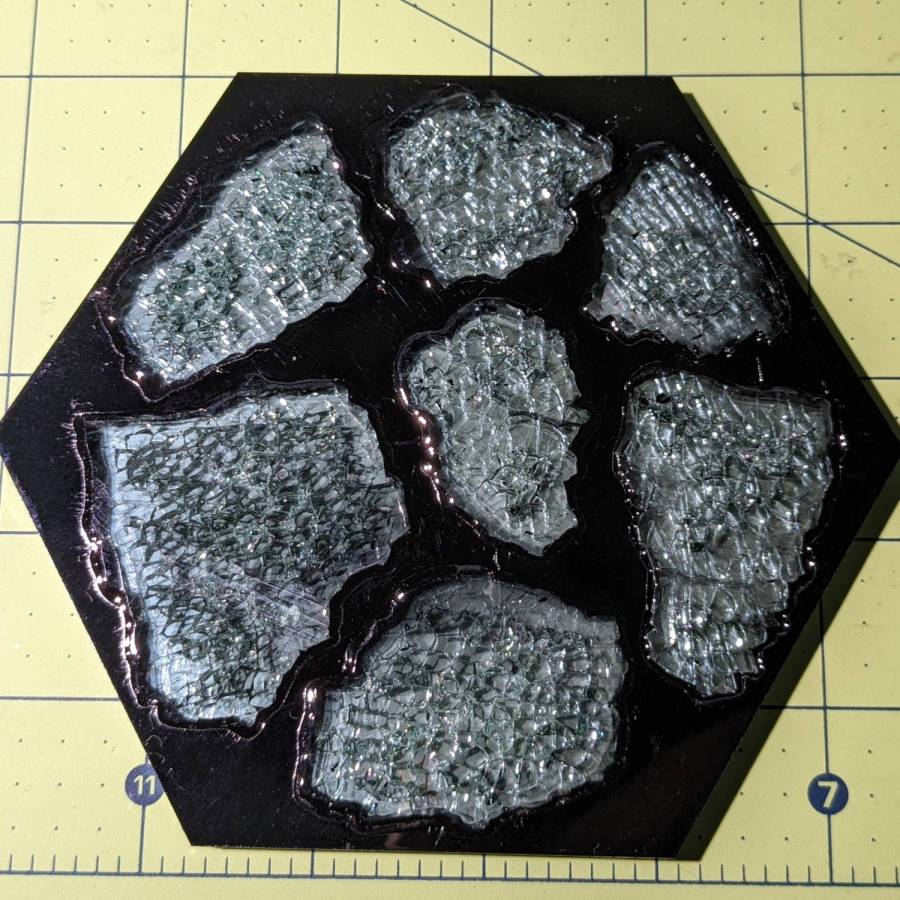
Peeling the paper away exposes an almost perfect surface, with the epoxy forming a slight curve between the black acrylic and the glass:
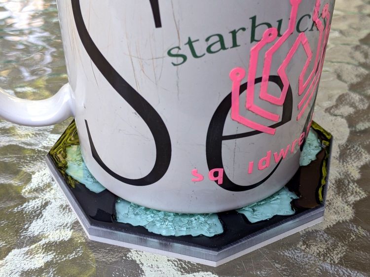
Smashed Glass Coaster 2 – overview
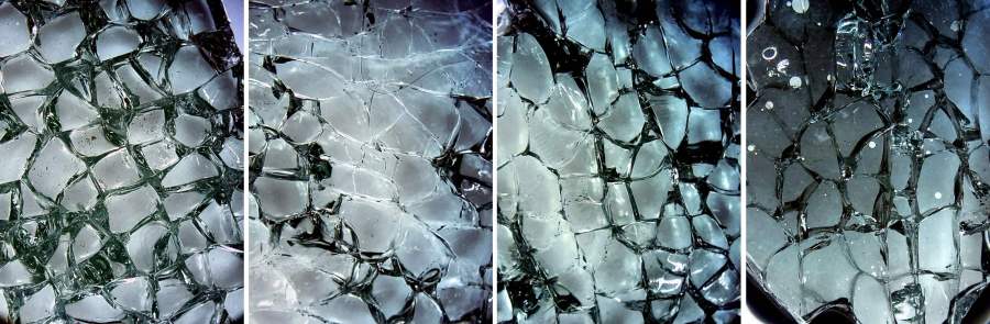
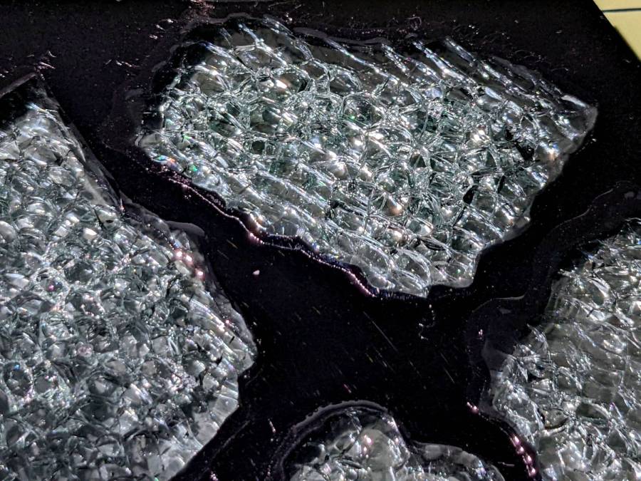
The mirror doubles the number of glass cuboids and their glittery gaps:
Smashed Glass Coaster 2 – fragment detail
All in all, it turned out well, but the epoxy pouring and leveling is tedious.
It might be possible to assemble a coaster upside-down, with the black layer stuck to something like Kapton tape and the fragments carefully aligned in their openings to make the entire top surface a plane. The tape should keep the epoxy from oozing out of the gaps, although a perfect seal may be impossible.
Then fill the gaps with black epoxy, lay the clear middle layer in place, run a dollop of epoxy on each fragment, lay the mirror in place, and hope there’s enough epoxy to fill all the gaps and not enough to make a mess around the perimeter.
With a bit of luck, that wouldn’t require so much hand finishing.
The next coaster must have a perimeter shrinkwrapped around the fragments, if only to break the low-vertex-count polygon tradition.
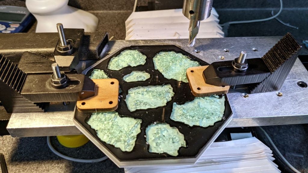
So I clamped it to the Sherline’s tooling plate and milled off the rim:
Smashed Glass Coaster – meniscus removal
Given the Sherline’s cramped work envelope, all the action took place along the rearmost edge, requiring eight reclampings indexed parallel to the table with a step clamp.
The cutter cleared off everything more than 0.3 mm above the surface of the glass chunks. I could probably have gone another 0.1 mm lower, but chopping the bit into the edge of a shattered glass fragment surely wouldn’t end well.
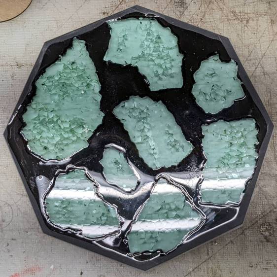
Polishing the dark gray milled surface might improve it slightly, at the risk of scuffing whatever poured epoxy stands slightly proud of the glass:
Smashed Glass Coaster – leveled edge
Perhaps if I define it to be a border, everybody will think it was intentional.