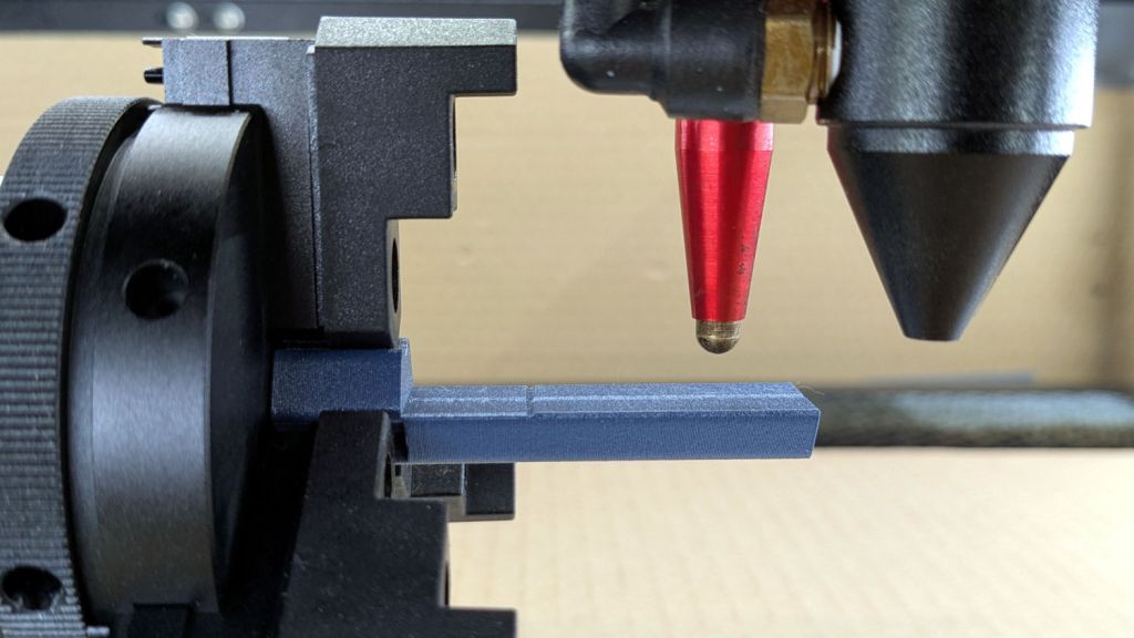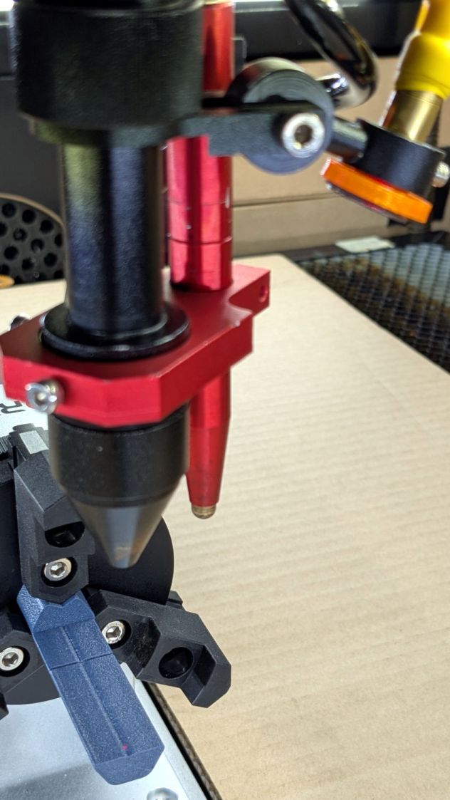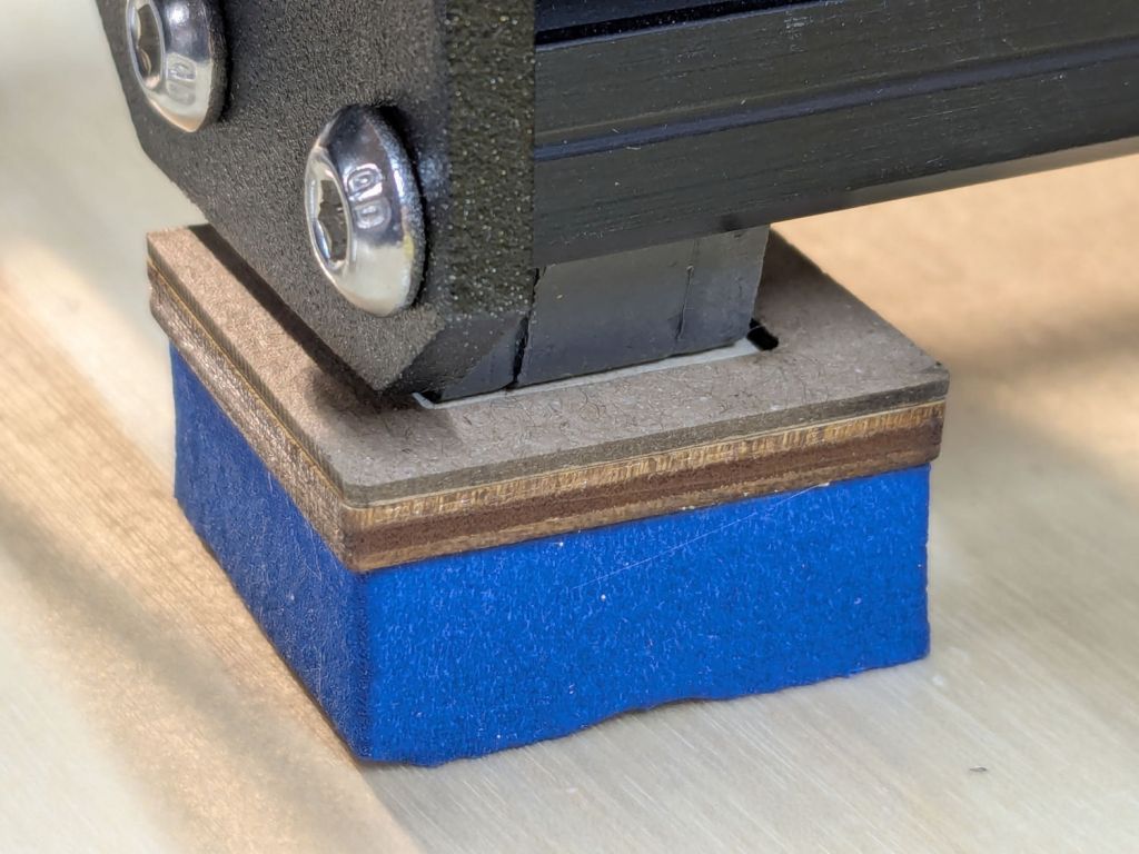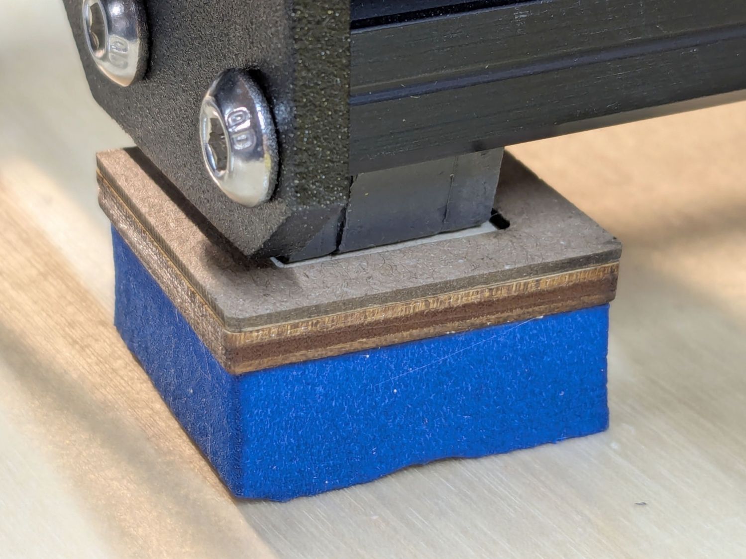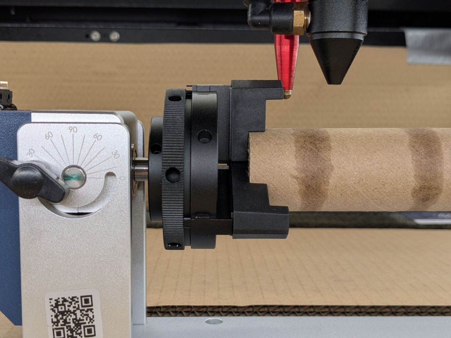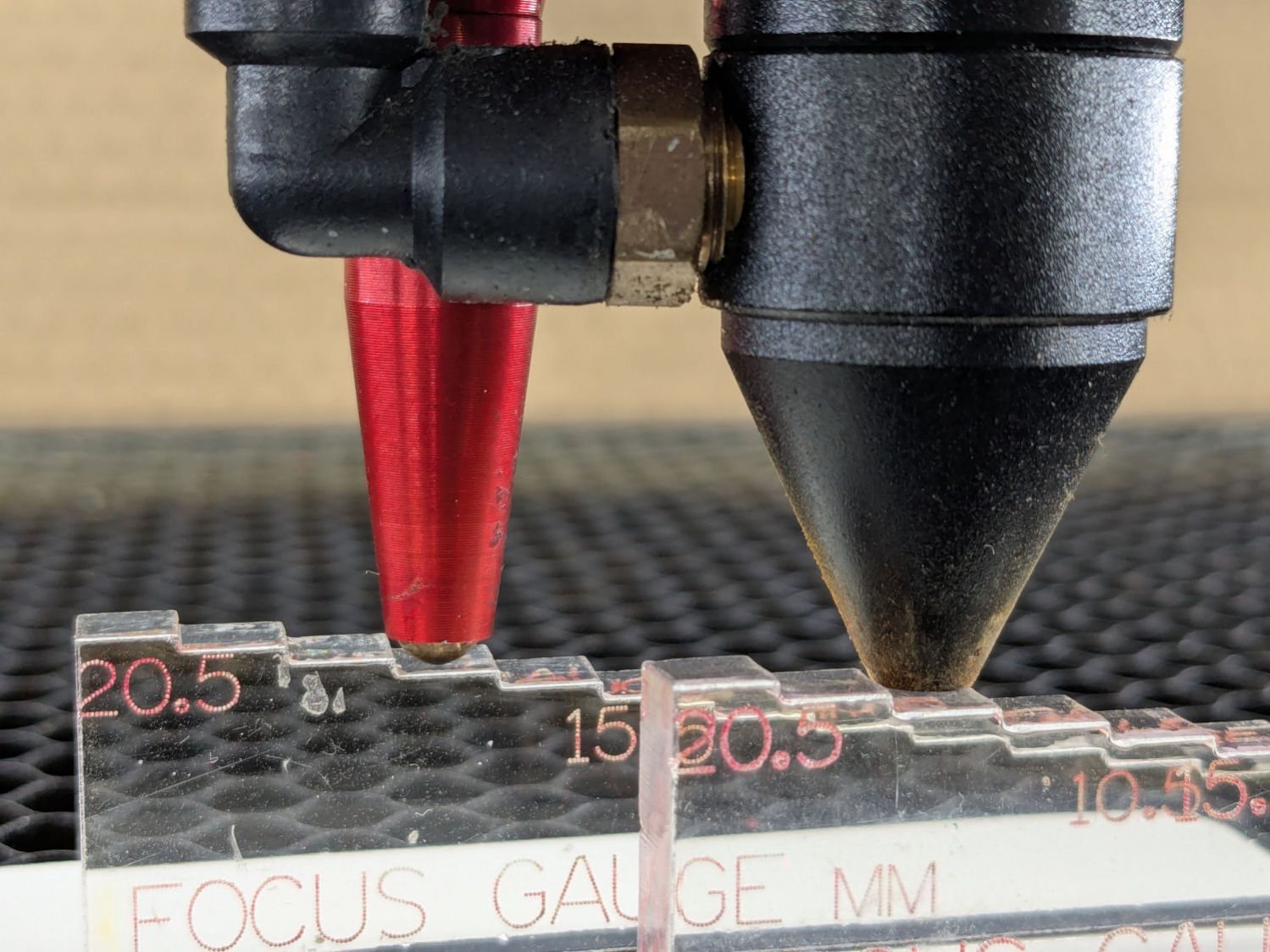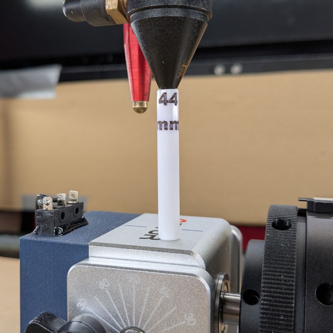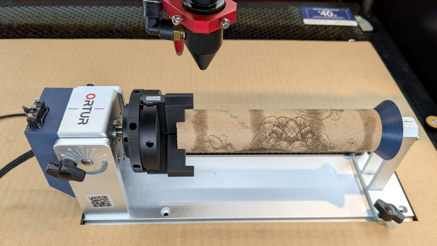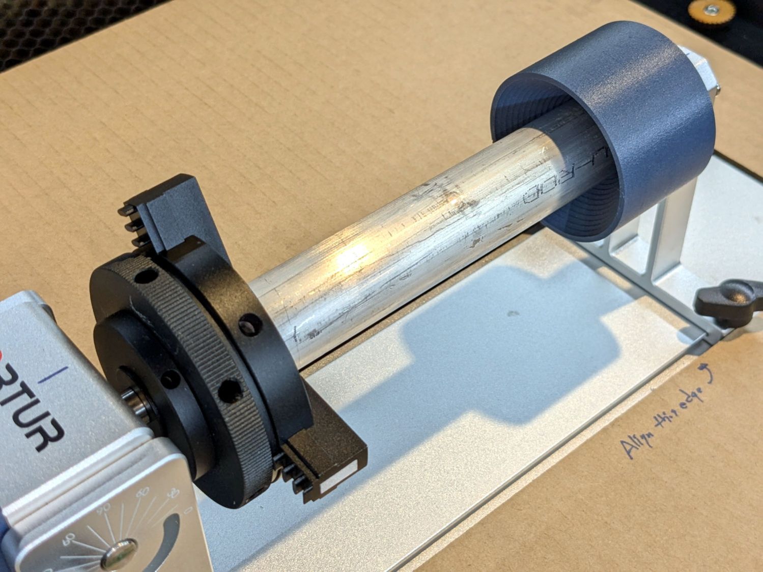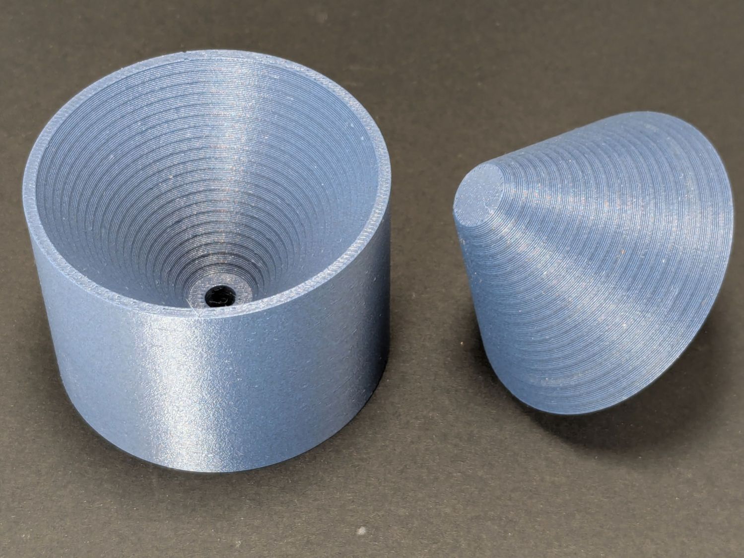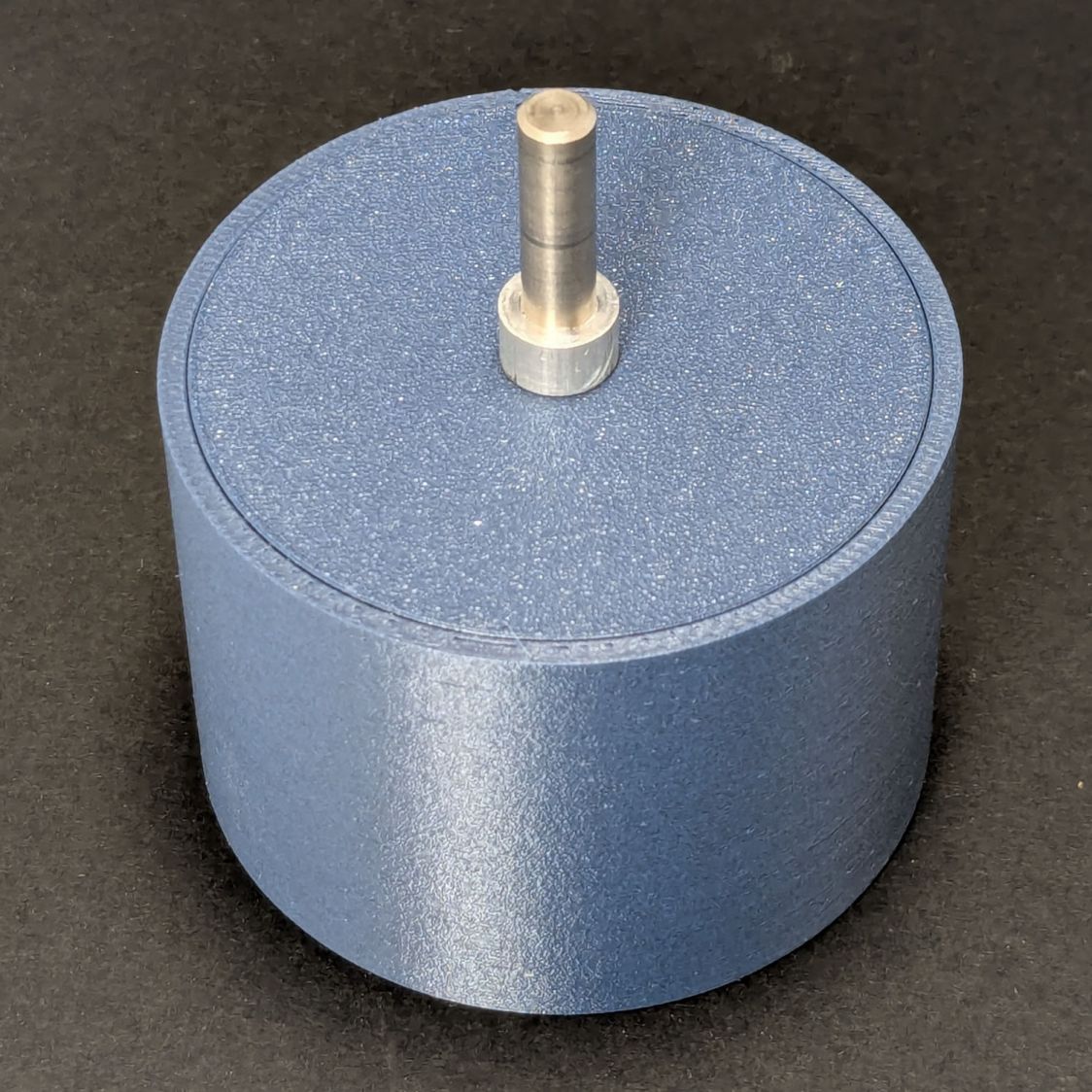
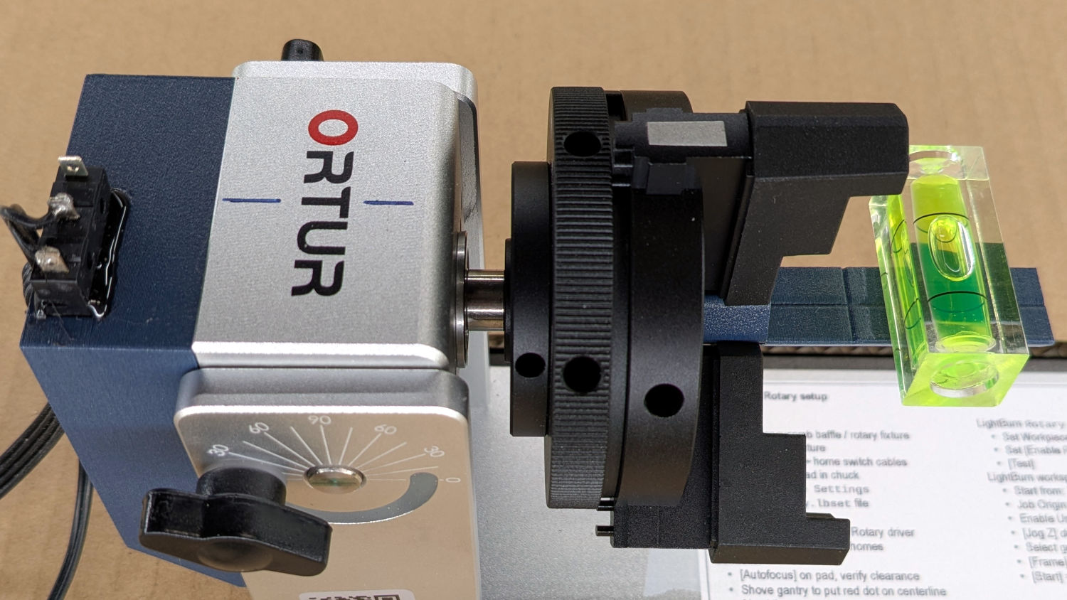
The standard jaws for the Ortur Rotary loom over small-diameter workpieces:
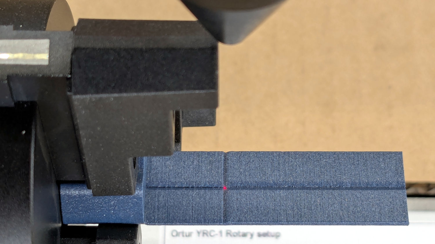
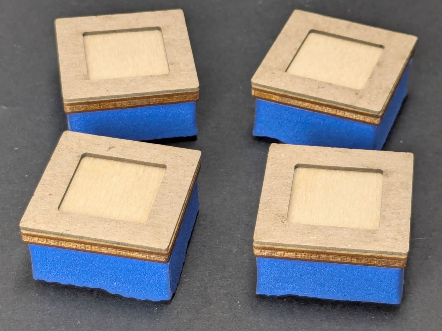
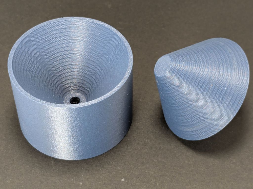
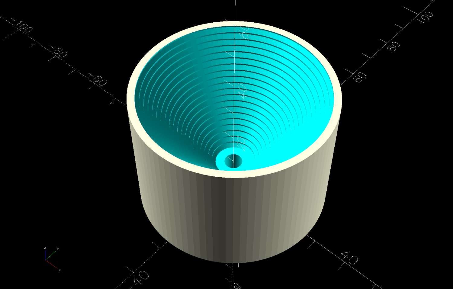
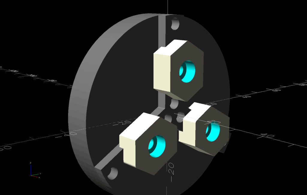
Some measuring and modeling produced petite 3D printed jaws:
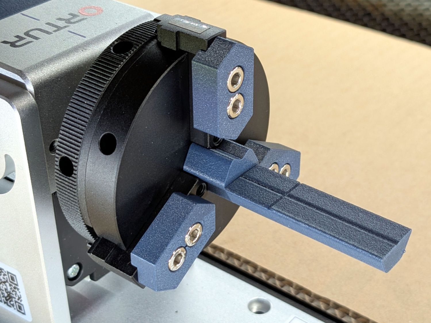
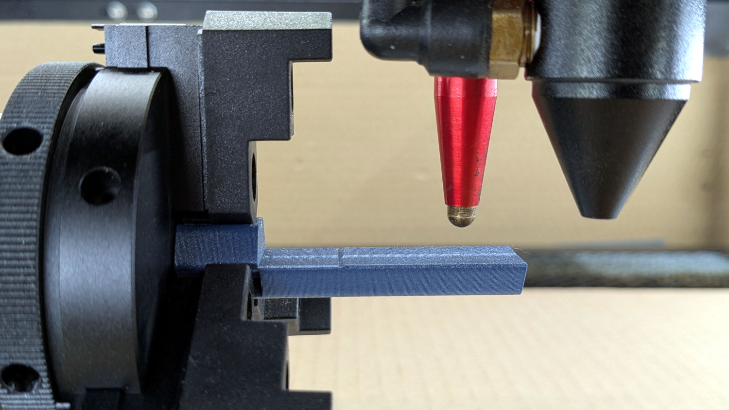
Admittedly, those jaws aren’t doing much of anything, but they’re not nearly as much in the way. You (well, I) can screw them in closer to the center to overlap the chuck jaws or another hole outward for slightly larger cylinders.
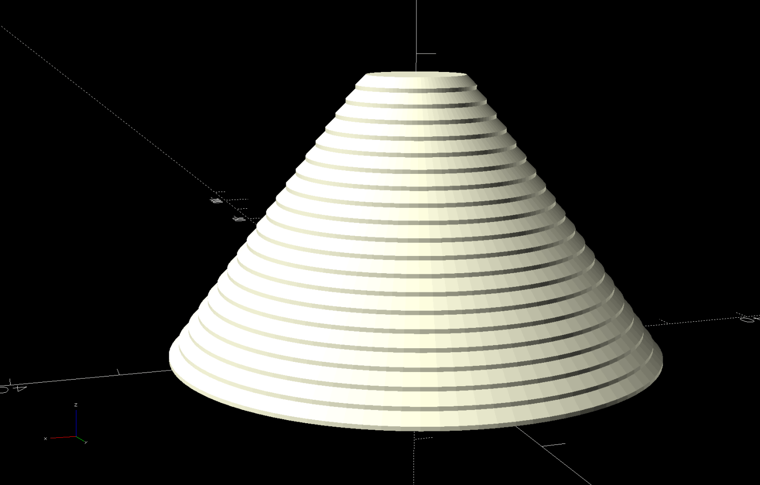
The solid model looks about the same:

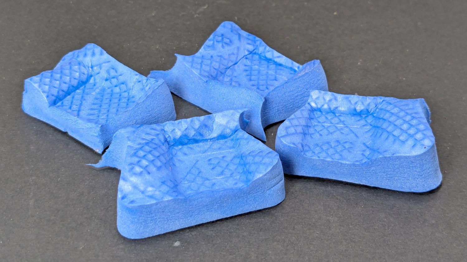
They build face-down with a little support under the screw recesses for a clean fit on the chuck:

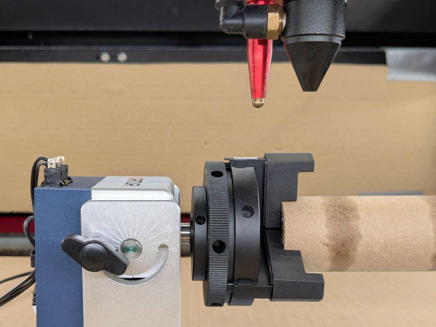
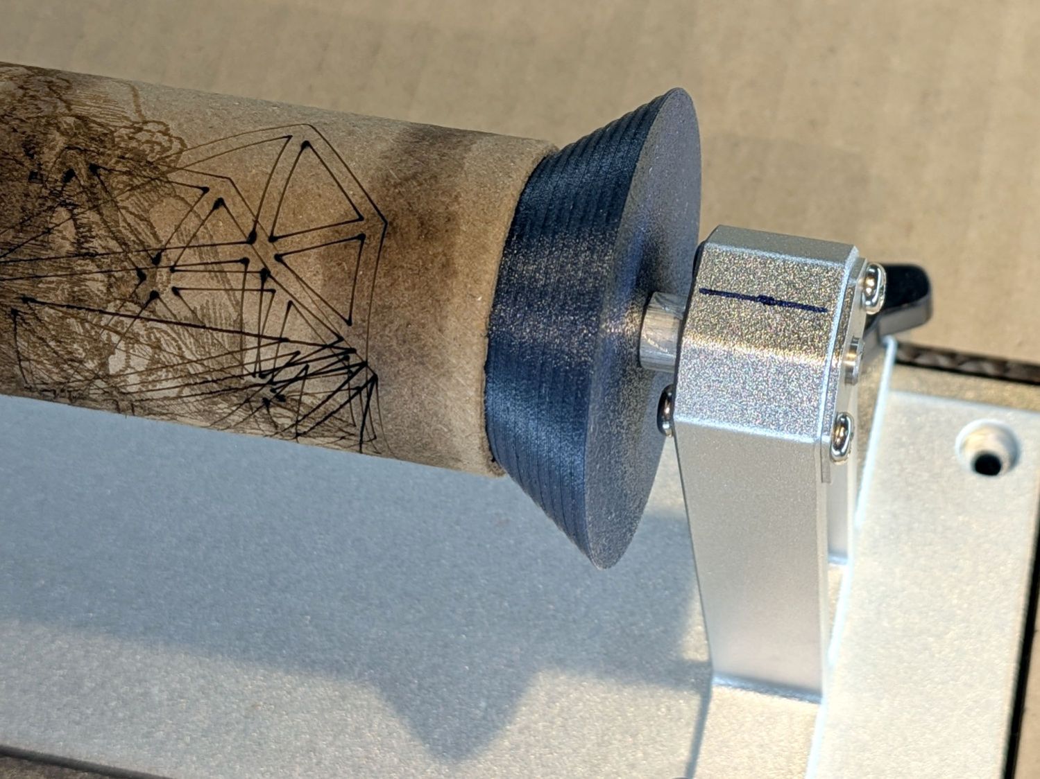
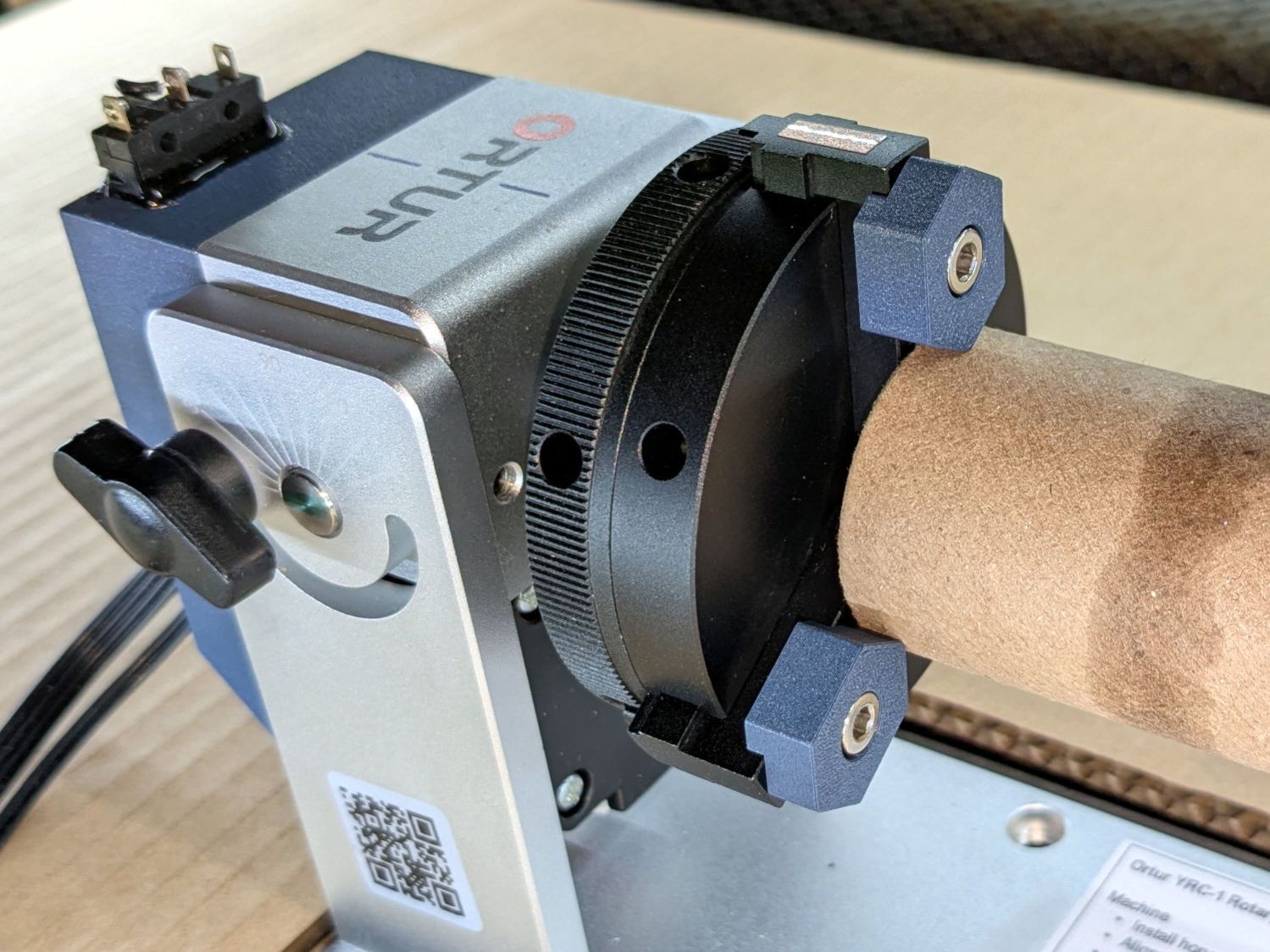
Teeny jaws might be handy:

Screwing them in one hole outward lets them grip medium cylinders without sticking out from the chuck jaws:
The OpenSCAD code lets you pick which screw holes you want, but it does not error-check the perverse choices.
The OpenSCAD source code as a GitHub Gist:
| // Ortur Rotary Focus Pad | |
| // Ed Nisley – KE4ZNU | |
| // 2026-01-04 | |
| include <BOSL2/std.scad> | |
| Style = "Show"; // [Build,Show,Chuck,ChuckJaw,Jaw] | |
| InnerScrew = 1; // [0:3] | |
| OuterScrew = 3; // [2:4] | |
| /* [Hidden] */ | |
| ID = 0; | |
| OD = 1; | |
| LENGTH = 2; | |
| HoleWindage = 0.2; | |
| Protrusion = 0.1; | |
| Gap = 5.0; | |
| NumSides = 8*3*4; | |
| $fn=NumSides; | |
| WallThick = 2.0; | |
| ScrewHead = [4.0 + HoleWindage,7.0 + HoleWindage,4.0]; | |
| ChuckOD = 66.0; | |
| ChuckThick = 10.0; | |
| ChuckBCR = [3.5,7.5,15.0,22.5,30.0]; // M4 tapped in chuck jaws | |
| ChuckJawOA = [ChuckOD/2,8.0 + HoleWindage,3.5]; | |
| JawBlock = [0,15.0,2*WallThick + ScrewHead[LENGTH]]; // .x will be variable | |
| JawRound = 1.0; // tip rounding | |
| //—– | |
| // Single chuck jaw with holes | |
| module ChuckJaw(Holes=true) { | |
| difference() { | |
| intersection() { | |
| cuboid(ChuckJawOA,anchor=BOTTOM+LEFT); | |
| cyl(ChuckJawOA.z,d=ChuckOD,anchor=BOTTOM); | |
| linear_extrude(h=ChuckJawOA.z) | |
| hexagon(od=ChuckOD,rounding=2.0,anchor=LEFT); | |
| } | |
| if (Holes) | |
| for (i = [0:len(ChuckBCR)-1]) | |
| right(ChuckBCR[i]) | |
| down(Protrusion) | |
| cyl(2*ChuckJawOA.z,d=ScrewHead[ID],anchor=BOTTOM); | |
| } | |
| } | |
| // Chuck layout | |
| module Chuck(Holes=true) { | |
| cyl(ChuckThick,d=ChuckOD,anchor=TOP) position(TOP) | |
| for (a = [0:120:360]) | |
| zrot(a) | |
| ChuckJaw(Holes); | |
| } | |
| // Gripping jaw | |
| module Jaw(Screws=[1,3]) { | |
| HoleOC = ChuckBCR[Screws[1]] – ChuckBCR[Screws[0]]; | |
| JawOAL = HoleOC + ScrewHead[OD] + 2*WallThick + (JawBlock.y/2)/cos(30); | |
| difference() { | |
| left(JawOAL/2) | |
| intersection() { | |
| cuboid(JawBlock + [JawOAL,0,0],anchor=BOTTOM+LEFT); | |
| linear_extrude(h=JawBlock.z) | |
| hexagon(od=ChuckOD,rounding=JawRound,anchor=LEFT); | |
| right(JawOAL) | |
| linear_extrude(h=JawBlock.z) | |
| hexagon(od=ChuckOD,rounding=JawRound,anchor=RIGHT); | |
| } | |
| right(0*JawOAL/2) | |
| for (i=[-1,1]) | |
| right(i*HoleOC/2) { | |
| down(Protrusion) | |
| cyl(JawBlock.z,d=ScrewHead[ID],anchor=BOTTOM); | |
| up(2*WallThick) | |
| cyl(JawBlock.z,d=ScrewHead[OD],anchor=BOTTOM); | |
| } | |
| down(Protrusion) | |
| cuboid([JawOAL,ChuckJawOA.y,WallThick + Protrusion],anchor=BOTTOM); | |
| } | |
| } | |
| //—– | |
| // Build things | |
| if (Style == "Chuck") { | |
| Chuck(); | |
| } | |
| if (Style == "Show") { | |
| xrot(180) | |
| yrot(90) { | |
| color("Gray",0.8) | |
| Chuck(); | |
| up(ChuckJawOA.z – WallThick) | |
| for (a = [0:120:360]) | |
| zrot(a) | |
| right((ChuckBCR[InnerScrew] + ChuckBCR[OuterScrew])/2) | |
| Jaw(Screws=[InnerScrew,OuterScrew]); | |
| } | |
| } | |
| if (Style == "ChuckJaw") | |
| ChuckJaw(); | |
| if (Style == "Jaw") { | |
| Jaw(Screws=[InnerScrew,OuterScrew]); | |
| } | |
| if (Style == "Build") | |
| for (j=[-1:1]) | |
| fwd(j*(JawBlock.y + Gap)) | |
| up(JawBlock.z) xrot(180) | |
| Jaw(Screws=[InnerScrew,OuterScrew]); | |