Ed Nisley's Blog: Shop notes, electronics, firmware, machinery, 3D printing, laser cuttery, and curiosities. Contents: 100% human thinking, 0% AI slop.
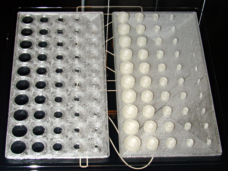
Despite the profusion of surface-finish and print quality test objects, I really care about the dimensions of a 3D printed object, because I tend to build widgets rather than art objects. These two objects, from walter’s Hole and Column Test Print, produce calibrated holes and columns from 0.20 mm to 10.00 mm in diameter, incrementing by 0.20 mm, that should slip neatly together:
M2 – walter hole-column test
Of course, they didn’t, but they came surprisingly close for a first attempt.
The 0.20 and 0.40 posts simply aren’t there, because they’re too small to print with a 0.35 mm diameter nozzle. The 0.60 through 1.40 mm posts were present, albeit fugly, and posts larger than that looked increasingly better.
Although all the holes were present, in the sense that you could see a disturbance in the top and bottom infill pattern, the first visibly open hole appeared at the 0.80 mm spot… and it was immeasurably small. Some holes had misplaced perimeter strands stretching across the openings, which is probably due to excessive speed from my fiddling around with the numbers.
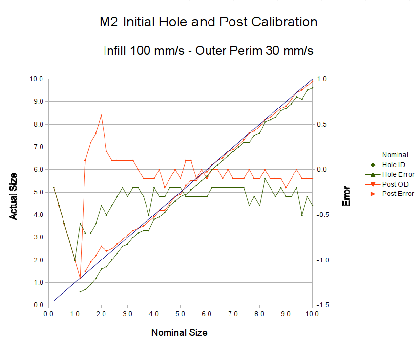
Measuring them with a digital caliper, with no effort at finding the best orientation, then slapping the data into a Libreoffice spreadsheet, produces an interesting graph:
M2 – Initial Hole and Post Diameter Calibration
Above about 3 mm diameter: posts are 0.1 mm too small and holes are 0.3 mm too small. Around 2 mm, posts are too big and holes are way too small. What’s important: above maybe 2.5 mm, the error is essentially constant and does not scale with diameter, so a simple Finagle Constant (or two) can solve (most of) the problem.
Some experiments involving slic3r’s small-perimeter speed seem in order; it was 25 mm/s for these pieces.
More care in measurement would produce better answers, but the real question is whether you can produce holes and columns with known sizes; the answer (as expected) remains “with some care”. That’s not surprising; I expect to have an M2 + PLA version of the small hole diameter Finagle Constant that I’ve been using with Skeinforge + Thing-O-Matic; the correction will certainly fall in the same ballpark.
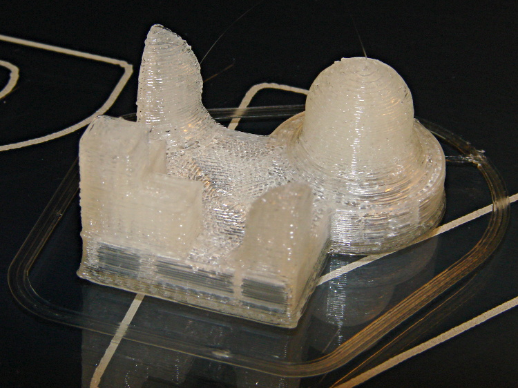
This object from whpthomas’s collection exercises the deprime operation in Sailfish, but it seemed like it’d be useful to verify the Marlin settings in the M2:
M2 – whpthomas deprime test
From the other side:
M2 – whpthomas deprime test – view 2
Yes, that was rather anticlimactic. No ooze, no stringing, no surface finish blemishes, just the finished object on the build platform’s glass sheet.
I like that!
The slight bumps on the sharp corner edges seem to be due to the crazy-high perimeter and infill speeds I’ve been playing with, although (I think) those are also where layer changes occurred. The first layer height came out a bit short, so there’s a small flange around the object’s bottom edge; I was figuring out how to get a precise level across the entire surface and stabilize the Z-min switch operation.
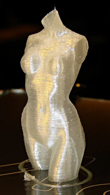
The M2 and slic3r produced this, with the conspicuous vertical bars coming from the 0.10 infill:
M2 – Pink Panther Woman – front
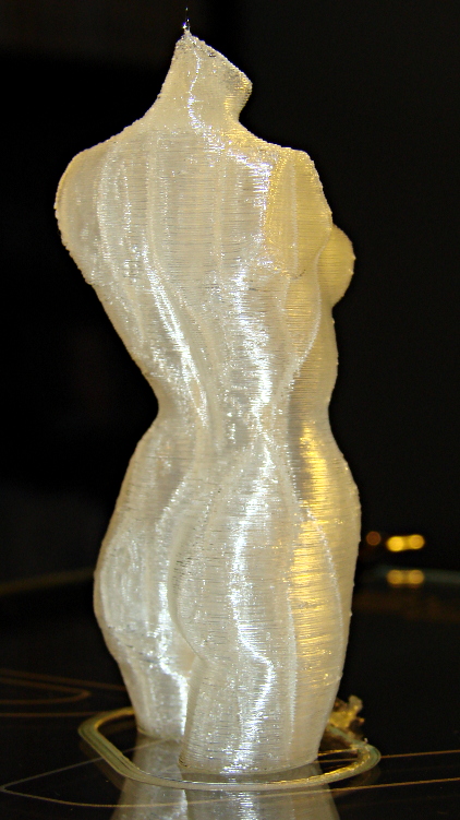
From the rear:
M2 – Pink Panther Woman – rear
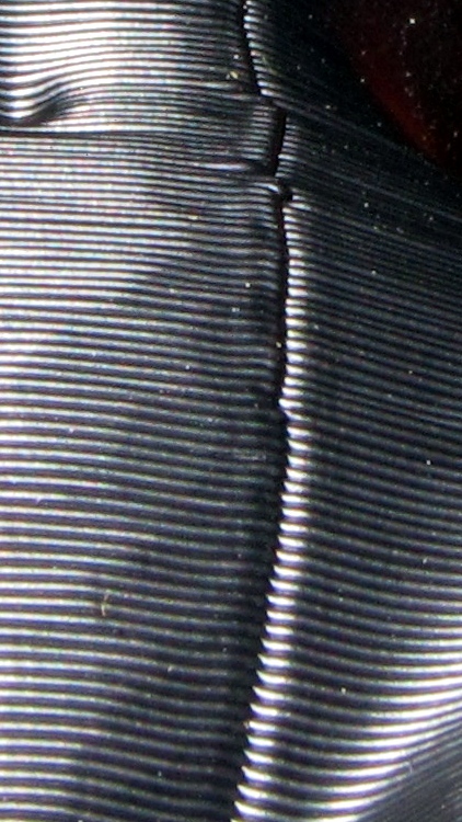
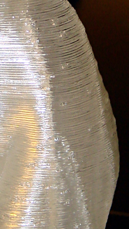
A detail of the left hip shows that slic3r distributes the reversal zits, rather than lining them up in neat columns, and the M2 does a much better job of not depositing blobs at reversals:
M2 – Pink Panther Woman – hip detail
I picked 1.0 mm retraction at either 100 or 300 mm/s, pretty much out of thin air, but even some fine tuning can’t improve that very much. The zits are recessed, so the retraction may be slightly too enthusiastic.
You’ve seen the overview pictures of the half-scale cushwa Owlearlier, so here are some details…
The front view:
M2 – cushwa Owl – half scale
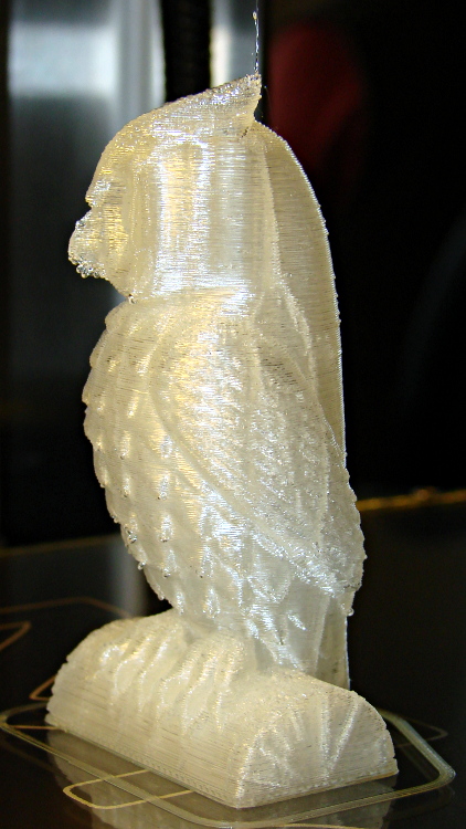
The left side view:
Owl – half size – left
The conspicuous vertical lines come from the 0.10 infill honeycomb; there are no visible retraction zippers and the surface is smooth to the touch.
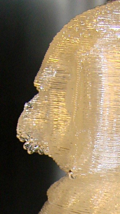
A closeup of the beak shows the crystal-clear drooping filament; a similar effect happened on the downward-pointing feather tips. Generally, this is a sign of too-hot extrusion, but at 165 °C I’m not convinced that’s applicable. It may simply be too much overhang at this scale:
M2 – cushwa Owl – beak detail
Overall, it’s pretty good. The config info doesn’t include the external perimeter speed, which I’ve been dialing back from an insanely high value. I think it was 75 for this one, which might be flinging the filament off the edge of the beak below that steep overhang.
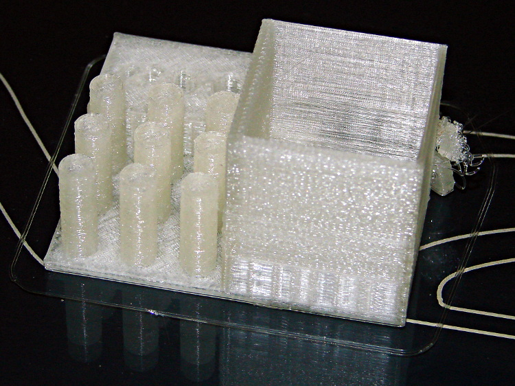
The arch foot broke loose from the platform after it grew to about 8 mm, but that seems to happen with most of the DIY printers. Apart from the tangle produced by that flaw, the rest of the object came out essentially perfect:
M2 – MAKE Magazine Torture Test – box and pillars
The surface finish is rougher than I think it should be, but the dense zigzag infill on the two thicker solid walls of the box seems to disturb their outer finish; the two thinner walls have linear fill and are fine.
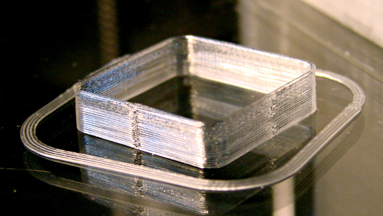
Building these things seems to be the simplest and best way to figure out whether you have all the pieces flying in formation:
Thinwall box – first success
I took that picture after cracking them off the glass plate, then putting them back: the box really does line up with the skirt while printing. There’s another object visible in the background; that little box really was the first completely successful object.
It’s adapted from Coasterman’s classic calibration set, redone in OpenSCAD so it’s easy to modify. A pair of Minkowski sums produce two shapes that ensure the wall remains exactly one thread wide all the way around the perimeter.
When your printer can print one of these, then you can move on to more complex objects, secure in the knowledge that you’ve established:
Proper bed leveling and height setting: measure the skirt thickness
Both the layer thickness and width match your settings
Extrusion temperature: not too hot, not too cold
Printing speed / acceleration for all layers
First layer adhesion to platform
Minimum layer time to prevent melting / slumping
Filament diameter
Extrusion “packing density” multiplier: the fundamental fudge factor
Accurate steps/mm for all axes to get exact XYZ dimensions
Mechanical stability and rigidity
Basically, this object leaves no place for errors to hide. It doesn’t check infill, the various perimeter speeds, solid layers, and suchlike, but all the fundamentals must be correct or you’ll see painfully obvious flaws.
For example, there’s a bit of a zipper at the layer changes. It’s better than the Thing-O-Matic ever was, but it improved as I twiddled the Retraction settings on later objects.
No, the first few didn’t work quite that well:
M2 – Thinwall box with previous attempts
For what it’s worth, the last problem turned out to be a loose setscrew in the X axis motor pulley that produced a layer shift that closely resembled a stepper motor losing steps. All of the setscrews now sport a dab of low-strength Loctite, so that problem shouldn’t happen again.
Being that type of guy, my Start and End G-Code routines are somewhat more elaborate than usual…
The Start routine handles homing, which is more dangerous than you might think, and wiping the drool off the nozzle:
;-- Slic3r Start G-Code for M2 starts --
;  Ed Nisley KE4NZU - March 2013
M140 S[first_layer_bed_temperature]	; start bed heating
G90				; absolute coordinates
G21				; millimeters
M83				; relative extrusion distance
M84				; disable stepper current
G4 S3			; allow Z stage to freefall to the floor
G28 X0			; home X
G92 X-95		; set origin to 0 = center of plate
G1 X0 F30000    ; origin = clear clamps on Y
G28 Y0			; home Y
G92 Y-125		; set origin to 0 = center of plate
G1 Y-122 F30000    ; set up for prime near front edge
G28 Z0			; home Z
G92 Z1.0		; set origin to measured z offset
M190 S[first_layer_bed_temperature]	; wait for bed to finish heating
M109 S[first_layer_temperature]		; set extruder temperature and wait
G1 Z0.0 F2500	; plug extruder on plate
G1 E10 F300		; prime to get pressure
G1 Z5 F2500		; rise above blob
G1 Y-115 F30000	; move away
G1 Z0.0 F2500	; dab nozzle to remove outer snot
G4 P1			; pause to clear
G1 Z0.1			; clear bed for travel
;-- Slic3r Start G-Code ends --
The fundamental problem with homing is that you don’t know where the nozzle stands in relation to the build platform and the bulldog clips clamping the glass plate to the aluminum heater. If you simply home X and Y with Z unchanged, you will eventually plow the nozzle directly across a clip. Trust me on this, you do not want to do that.
So Line 7 disables the stepper motors. In an ideal world, the Z axis stage would then free-fall to the bottom of the chassis during the 4 second pause produced by the G4 S3 instruction. In the real world, that works most of the time, but the platform sometimes sticks where it is. You don’t want to home the Z axis to the top of its travel, because that will eventually crunch the nozzle into those clips, so I plan to add a bottom limit switch so I can drive the platform to a known location away from everything else.
The default M2 Start G-Code puts the XY origin at the front left side of the platform, following the RepRap convention. Maybe it’s just me, but having the origin in the middle of the platform makes more sense for my objects; most of my OpenSCAD models are more-or-less symmetric, so putting the XY origin at their center works well. Ultimately, it doesn’t matter as long as you’re consistent, but my Start G-Code doesn’t produce the same results as the Makergear setup.
Line 9 homes the X axis and Line 10 sets the coordinate to -95. The X axis home position is about 5 mm from the left edge of the glass plate, so the nozzle has about 195 mm of travel to the right edge of the 200 mm plate. The X=0 origin will be in the middle of the printable range, with -95 mm to the left limit (the home position) and +95 to the right edge; the nozzle can travel another 30 mm beyond the right edge to about +125. Line 11 puts the nozzle in the middle of its travel at X=0.
Line 12 homes the Y axis and Line 13 sets the coordinate to -125. The Y axis home position is almost exactly on the front edge of the 250 mm glass plate, so the Y=0 origin is centered on the plate. The nozzle can travel an additional 10 mm off the rear edge of the plate. Note that you must position the nozzle somewhere on the X axis that avoids the bulldog clips; any of X=±95 or X=0 will work. Line 14 puts the nozzle in the middle of the plate at Y=0; it’s already at X=0, so the plate is now centered.
Line 15 homes the Z axis. I’ve set the limit switch so that the home position leaves exactly 1.0 mm between the nozzle and the glass plate, which I find easier to measure than the Makergear suggestion of 0.1 mm. Of course, that’s because I have a Starret taper gauge in my tool cabinet. Use what you have, but use it consistently.
Line 16 sets the Z axis coordinate position to +1.0 mm, matching the measured height, so that Z=0 corresponds to the nozzle exactly kissing the glass plate. The Makergear defaults put Z=0 about 0.1 mm above the platform; I’d rather apply model- and material-dependent offsets to “natural” machine positions.
All of that ignores Z axis backlash. Some preliminary guesstimates put that around 0.1 mm, far better than my Sherline, but still large with respect to the layer thickness. I need more measurements of that, plus some measurements of the actual glass flatness. I think the glass bows upward by about 0.1 mm in the middle, but that requires better probing that will be easier under LinuxCNC control where I can do automated platform mapping.
With the nozzle parked 1.0 mm over the platform, the next two lines wait for everything to reach the proper temperature. I preheat the platform and crank up the extruder temperature before starting the program , so these steps don’t take too long.
However, the nozzle cools off as the drool contacts the much colder platform (it’s heated to 70 °C, but that’s cooler than 150-ish °C by a considerable margin) and the PID loop struggles to reheat it. I think that’s due to the default I term being only 0.1, which reduces integral windup during preheating, but also slows recovery from a sudden thermal load. It helps to preheat the nozzle about 10 °C over the desired temperature, then let it cool during this step.
M2 – Wipe blobs on glass platform
Line 19 uses Nophead’s trick (which I cannot find now) of planting the nozzle on the plate at Z=0.0 to reduce drool, although I do that after the nozzle reaches extruding temperature. The drool forms a blob on the platform as the nozzle heats, but the nozzle punches directly through it on the way to Z=0.0.
Line 20 runs 10 mm of filament into the hot end to pressurize the extruder. Some of the molten goo oozes out around the nozzle, enlarging the blob on the glass plate. The object of the game is to leave all that behind: having a generous contact patch on the glass helps.
The larger blob on the left of the picture (at Y=-125) comes from that process.
Line 21 starts the wiping dance:
Raise the nozzle above the blob to Z=5 mm
Move away from the blob by 5 mm. I’ll probably change this to move in the +X direction.
Tap the nozzle on the platform, so (almost all of) the molten PLA slides away from the orifice
Get 0.1 mm of clearance from the platform, directly over the new blob
Scoot off to print a Skirt extrusion around the object
The smaller, rather flat, blob on the right comes from the nozzle tap. A thin hair may stretch from the blob to the start of the skirt, but it doesn’t amount to much.
Sometimes, of course, the blobs don’t adhere to the glass plate and accompany the nozzle to the start of the skirt. By the conservation of perversity, that’s also when the skirt starts on the far side of the origin, so the blob smears all over the object’s first layers. The Makergear wipe process extrudes the waste filament over the side of the plate, then shears it off as the nozzle returns to the surface; I’ll try blending that in with my startup sequence at some point.
My slic3r configuration extrudes at least 15 mm of filament into the skirt, giving the extruder plenty of time to reach a steady state before starting the actual object. Generally that’s far more than enough filament, but sometimes … well, it’s a good idea to watch what’s going on.
On the other end of the printing process, the End G-Code routine handles shutdown with the object on the platform:
;-- Slic3r End G-Code for M2 starts --
;  Ed Nisley KE4NZU - March 2013
M104 S0		; drop extruder temperature
M140 S0		; drop bed temperature
M106 S0		; bed fan off
G1 Z195	F2500	; lower bed
G1 X0 Y0 F30000	; center nozzle
M84     	; disable motors
;-- Slic3r End G-Code ends --
Line 3 begins turning the heaters and bed fan off. I’ve unplugged the fan for now, so Line 5 is just for completeness.
Line 6 lowers the bed to the bottom under power, because that’s faster that a free fall and it’s guaranteed to work.
With the object safely out of the way, Line 7 centers the nozzle over the platform.
Finally, Line 8 turns off the steppers off; the platform drops another few millimeters
Then everything cools down. Because I run the platform at well above PLA’s glass transition temperature, it must cool for quite a while until the object stiffens up.