Ed Nisley's Blog: Shop notes, electronics, firmware, machinery, 3D printing, laser cuttery, and curiosities. Contents: 100% human thinking, 0% AI slop.
Which small spot on this hot-air furnace heat exchanger isn’t like all the other small spots?
Pinhole in furnace heat exchanger
Correct! The orange one at the corner of the rectangular exhaust gas flue that’s lit up like the sun, because you’re looking directly into the oil burner flame.
With the fire off and everything cooled down, it looked like this:
Pinhole in furnace heat exchanger – detail
Now, this calls for a new furnace (because replacing the heat exchanger costs as much as a new furnace), but as it turns out this was in an unoccupied house during the week before Christmas. So I scrubbed off the debris with a steel brush, bent up a snippet of 2 mil brass shimstock to fit the corner, applied a layer of JB Industro-Weld epoxy to the problem, and positioned 200 W of incandescent bulbs to help it cure slightly sooner than forever:
Furnace heat exchanger – temporary fix
That is most certainly not a final repair, not just because the heat exchanger’s normal operating temperature exceeds the epoxy’s 500 °F rating, but because where there’s one pinhole there’s bound to be more. The goal was to let us keep the furnace running until we could schedule the replacement after the holidays. Remember, the building isn’t occupied and neither of the smoke / CO detectors went off at any point in the proceedings.
When the second hinge on my father-in-law’s scanner broke, he asked if I could fix it:
HP3970 Scanjet Lid – broken hinge
It’s a flatbed scanner, so the lid is nearly 18 inches long and weighs 2.2 pounds with the slide / negative backlight illuminator. The stress raiser notches, located exactly where the cracks started, look like a perfect example of how not to do these things.
I solvent-glued the hinges back together, with a square brass tube applying clamping force to the joint overnight, but this certainly won’t last for long:
HP3970 Scanjet Lid – crude repair
HP used to have some really smart engineers, but this looks like it was done by a Newkid (I was one, once, so I know the type) after a solid modeling and simulation session convinced him that those two thin plastic webs had enough strength for the job.
No. They. Do. Not.
Of course, HP provides no Official Way to repair that failure, as the hinges emerge seamlessly from the injection-molded plastic lid frame: you must scrap the scanner and buy a new one, because the lid would cost more than a new scanner. Equally of course, the fact that they don’t have a Windows driver beyond XP makes replacement a foregone conclusion.
It runs under Xubuntu 12.04, mostly, which is what I set him up with after the XP PC got compromised.
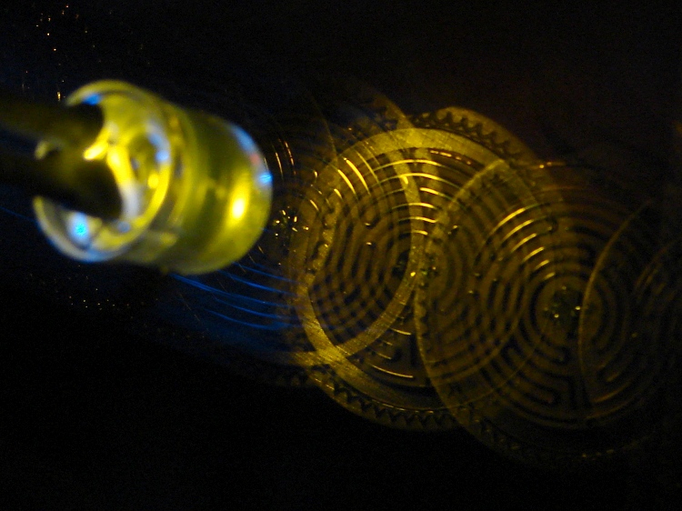
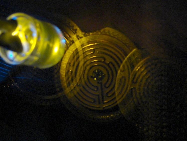
A bit of fiddling with the Arduino PWM hardware can turn a white LED into a stroboscopic tachometer to chop smooth motion into chunks:
Strobe – Maze 1 – 50 Hz 100 us
I was moving that pendant by hand and slight speed changes were easily visible:
Strobe – Maze 2 – 50 Hz 100 us
IBMers of a certain era may recognize the test object; the rest of you can go there.
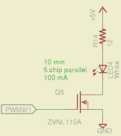
That’s a 10 mm warm-white LED with 5 parallel chips, running at about 100 mA from a 5 V supply, and driven from the same PWM channel and MOSFET that used to drive also drives the red channel of the RGB LED Mood Light:
White LED Strobe
The ZVNL110A MOSFET has a 3 Ω drain resistance, which becomes a significant part of the resistance; you’d want a bigger, better, lower resistance MOSFET to wring more light out of the LED. In fact, I ran the LED from 12 V with the same resistor at a few hundred mA.
The reason you need more light is to make up for the minuscule duty cycle. In order to “stop motion”, you want a very short pulse; I picked a 100 μs pulse. At 50 Hz, that works out to a 0.5% duty cycle: not much light at 100 mA, but OK for a demo.
You can’t do this with the standard Arduino PWM setup, because it produces a constant frequency (about 488 Hz) and varies the duty cycle; we need a variable frequency with a constant pulse length. Because a stroboscope needs fine-grained control over the frequency, in order to stop the motion of rotating objects, it should run from one of the 16 bit Timer1 PWM outputs, which means either PWM9 or PWM10. Note that simply changing the timer’s clock prescaler as described there won’t suffice, because that gives very coarse control of the PWM frequency.
It’s probably worth noting that trying to do precise timing purely in software with, say, the millis() and micros() functions, produces terrible results…
The Arduino timer hardware includes control over both the period and the duration of the output pulses. The Fine Manual describes all the timer configuration registers starting on page 109; see that post for a push-pull PWM driver that formed the basis of this one.
Fast PWM (Mode 14) has some useful characteristics:
Single-slope operation: timer counts only upward
Output PWM9 goes high when TCNT1 resets to 0
Output PWM9 goes low when TCNT1 = OCR1A
TCNT1 resets when TCNT1 = ICR1
The lowest possible output frequency occurs with ICR1 = 0xffff, so that Timer1 counts from 0x0000 to 0xffff before resetting (which, in that case, is indistinguishable from simply wrapping). The wrap period = ICR1 * tick period and the corresponding frequency = 1 / period.
The clock prescaler determines the overall range of Timer1 by setting the tick period. The Clock Select bit field can take on 6 useful, albeit widely separated, values (the other two select the external clock pin):
0 – stop timer
1 – prescale 1:1 = 62.5 ns tick → 244 Hz
2 – prescale 1:8 = 500 ns tick → 30 Hz
3 – prescale 1:64 = 4 μs tick → 3.8 Hz
4 – prescale 1:256 = 16 μs tick → 0.95 Hz
5 – prescale 1:1024 = 64 μs tick → 0.24 Hz
For my purposes, a lower limit around 4 Hz seemed about right. That means CS = 3, the prescaler runs at 1:64, and the timer ticks at 4 μs.
The frequency upper limit could be just under 1/(pulse width), which would produce a very high duty cycle. I arbitrarily set the limit to 1/(4 × pulse width), for a 25% duty cycle that works out to 1/(4 × 100 μs) = 2.5 kHz = 150 k flash/min. If you’re using very high current drive, then limit the duty cycle to prevent toasting the LED.
Because a strobe tach needs quick & easy adjustment, the encoder knob tweaks the pulse frequency in 1 Hz steps. Pushing the knob to close the shaft switch (if you have such a knob, of course, otherwise use another button; they all do the same thing here) reduces the step size to 0.01 Hz, which is more useful for fine tuning when you’re close to the goal. A real application requires better control over the numeric values (probably using integer values); I used floating point and simply ignored all the usual roundoff issues:
Shut off interrupts to prevent interference with the high byte storage register
Stop the timer: CS=0
Load the new upper limit in ICR1
Force TCNT1 to be just below IRC1 to terminate the current pulse
Start the timer: CS=3
Enable interrupts again
You’d probably plunk that into a separate function in a real program…
Printing the frequency becomes a hassle without floating point formatting in printf(). It should appear on the character LED display, too. Optionally / additionally showing the value in rev/min would be very nice.
You’d want to increment the frequency by some reasonable fraction of the current value, perhaps rounded to 1 / 2 / 5 / 10 percent steps. Larger steps by pushbutton? Truncate the current value to a multiple of the step size?
You would also want some way to adjust the flash duration, but that’s definitely in the nature of fine tuning.
As it stands, a 100 μs pulse really does stop motion:
Fan stopped at 2500 rpm
That’s a fan running at about 2500 rpm, with the LED flashing at 41.86 Hz. The camera exposure is 1/2 sec @ f/3.5, handheld, which means the camera integrated about 20 flashes. Ambient light accounts for the background blur: I boosted the grossly underexposed image right out of darkness. The square on the hub is retroreflective tape for a laser tachometer that verified the speed.
Yes, half a second handheld. The morning tea wears off during the day…
In round numbers, 41.86 Hz = 23.9 ms / rev. The fan diameter is 86 mm, so the blade tips travel 1.1 mm = (270 mm / 23.9 ms) × 100 μs during each flash. The tips seem slightly blurred when you (well, I) look very closely in real life, but I think this lashup worked pretty well right off the sketchpad.
The Arduino source code:
// Stroboscopic Tachometer
// Ed Nisley - KE4ANU - December 2012

//----------
// Pin assignments

const byte PIN_KNOB_A = 2;			// knob A switch - must be on ext interrupt 2
const byte PIN_KNOB_B = 4;			//  .. B switch
const byte PIN_BUTTONS = A5;		//  .. push-close momentary switches

const byte PIN_STROBE = 9;			// LED drive, must be PWM9 = OCR1A using Timer1

const byte PIN_PWM10 = 10;			// drivers for LED strip, must turn these off...
const byte PIN_PWM11 = 11;

const byte PIN_SYNC = 13;			// scope sync

//----------
// Constants

const int UPDATEMS = 10;				// update LEDs only this many ms apart

#define TCCRxB_CS 0x03					// Timer prescaler CS=3 -> 1:64 division

const float TICKPD = 64.0 * 62.5e-9;	// basic Timer1 tick rate: prescaler * clock

enum KNOB_STATES {KNOB_CLICK_0,KNOB_CLICK_1};

// ButtonThreshold must have N_BUTTONS elements, last = 1024

enum BUTTONS {SW_KNOB, B_1, B_2, B_3, B_4, N_BUTTONS};
const word ButtonThreshold[] = {265/2, (475+265)/2, (658+475)/2, (834+658)/2, (1023+834)/2, 1024};

//----------
// Globals

float FlashLength = 0.1e-3;						// strobe flash duration in seconds
word FlashLengthCt = FlashLength / TICKPD;		//  ... in Timer1 ticks

float FlashFreq = 20.0;							// strobe flash frequency in Hz
float FlashPd = 1.0 / FlashFreq;				//  ... period in sec
word FlashPdCt = FlashPd / TICKPD;				//  ... period in Timer1 ticks

float FreqIncr = 1.0;							// default frequency increment
const float FreqMin = 4.0;
const float FreqMax = 1.0/(4.0*FlashLength);

volatile char KnobCounter = 0;
volatile char KnobState;

byte Button, PrevButton;

unsigned long MillisNow;
unsigned long MillisThen;

//-- Helper routine for printf()

int s_putc(char c, FILE *t) {
  Serial.write(c);
}

//-- Knob interrupt handler

void KnobHandler(void)
{
	byte Inputs;
	Inputs = digitalRead(PIN_KNOB_B) << 1 | digitalRead(PIN_KNOB_A);  // align raw inputs
//	Inputs ^= 0x02;                             // fix direction

	switch (KnobState << 2 | Inputs) {
	case 0x00 : 				// 0 00 - glitch
        break;
	case 0x01 : 				 // 0 01 - UP to 1
        KnobCounter++;
		KnobState = KNOB_CLICK_1;
		break;
	case 0x03 : 				 // 0 11 - DOWN to 1
        KnobCounter--;
		KnobState = KNOB_CLICK_1;
		break;
	case 0x02 : 				 // 0 10 - glitch
        break;
	case 0x04 : 				 // 1 00 - DOWN to 0
        KnobCounter--;
		KnobState = KNOB_CLICK_0;
		break;
	case 0x05 : 				 // 1 01 - glitch
        break;
	case 0x07 : 				 // 1 11 - glitch
        break;
	case 0x06 : 				 // 1 10 - UP to 0
        KnobCounter++;
		KnobState = KNOB_CLICK_0;
		break;
	default :  					// something is broken!
        KnobCounter = 0;
		KnobState = KNOB_CLICK_0;
	}
}

//-- Read and decipher analog switch inputs
//		returns N_BUTTONS if no buttons pressed

byte ReadButtons(int PinNumber) {

word RawButton;
byte ButtonNum;

	RawButton = analogRead(PinNumber);

	for (ButtonNum = 0; ButtonNum <= N_BUTTONS; ButtonNum++){
		if (RawButton < ButtonThreshold[ButtonNum])
			break;
	}

	return ButtonNum;

}

//------------------
// Set things up

void setup() {
	pinMode(PIN_SYNC,OUTPUT);
	digitalWrite(PIN_SYNC,LOW);	// show we arrived

	analogWrite(PIN_PWM10,0);			// turn off other PWM outputs
	analogWrite(PIN_PWM11,0);

	analogWrite(PIN_STROBE,1);			// let Arduino set up default Timer1 PWM
	TCCR1B = 0;							// turn off Timer1 for strobe setup
	TCCR1A = 0x82;						// clear OCR1A on match, Fast PWM, lower WGM1x = 14
	ICR1 = FlashPdCt;
	OCR1A = FlashLengthCt;
	TCNT1 = FlashLengthCt - 1;
	TCCR1B = 0x18 | TCCRxB_CS;			// upper WGM1x = 14, Prescale 1:64, start Timer1

	pinMode(PIN_KNOB_B,INPUT_PULLUP);
	pinMode(PIN_KNOB_A,INPUT_PULLUP);

	KnobState = digitalRead(PIN_KNOB_A);
	Button = PrevButton = ReadButtons(PIN_BUTTONS);

	attachInterrupt((PIN_KNOB_A - 2),KnobHandler,CHANGE);

	Serial.begin(9600);
	fdevopen(&s_putc,0);				// set up serial output for printf()

	printf("Stroboscope Tachometer\r\nEd Nisley - KE4ZNU - December 2012\r\n");

	printf("Frequency: %d.%02d\nPulse duration: %d us\n",
		   (int)FlashFreq,(int)(100.0 * (FlashFreq - trunc(FlashFreq))),
		   (int)(1e6 * FlashLength));

	MillisThen = millis();

}

//------------------
// Run the test loop

void loop() {

	MillisNow = millis();

	if ((MillisNow - MillisThen) > UPDATEMS) {

		digitalWrite(PIN_SYNC,HIGH);

		Button = ReadButtons(PIN_BUTTONS);
		if (PrevButton != Button) {
			if (Button == N_BUTTONS) {
//				printf("Button %d released\n",PrevButton);
				FreqIncr = 1.0;
			}
			else
//				printf("Button %d pressed\n",Button);
//				if (Button == SW_KNOB)
					FreqIncr = 0.01;
			PrevButton = Button;
		}

		if (KnobCounter) {
			FlashFreq += (float)KnobCounter * FreqIncr;
			KnobCounter = 0;

			FlashFreq = constrain(FlashFreq,FreqMin,FreqMax);
			FlashFreq = round(100.0 * FlashFreq) / 100.0;

			FlashPd = 1.0 / FlashFreq;
			FlashPdCt = FlashPd / TICKPD;

			noInterrupts();
			TCCR1B &= 0xf8;				// stop Timer1
			ICR1 = FlashPdCt;			// set new period
			TCNT1 = FlashPdCt - 1;		// force immediate update
			TCCR1B |= TCCRxB_CS;		// start Timer1
			interrupts();

			printf("Frequency: %d.%02d\n",
				   (int)FlashFreq,(int)(100.0 * (FlashFreq - trunc(FlashFreq))));
		}

		digitalWrite(PIN_SYNC,LOW);

		MillisThen = MillisNow;
	}

}
That’s a grandiose name for a blinking LED, if I ever saw one…
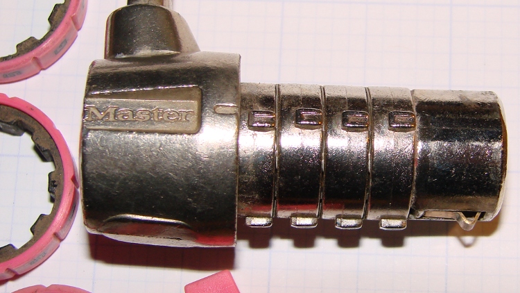
A Master Combination Lock emerged in locked condition from a box o’ stuff I handled during Mad Phil’s Great Cleanout. It’s not the highest security lock you’ll ever meet; about 15 minutes of fiddling produces the desired result:
Master Combo Padlock – opened
A bit of searching suggests it’s similar to the Master No. 1523D Combination Padlock, although this one came in pink. The doc describes how to change the combination:
Unlock (or crack) the lock
Pull off the spring-loaded endcap (I had to pry with a screwdriver)
Slide off the combination wheels
Reinstall in desired orientation
After removing the cap and wheels, it looks like this:
Master Combo Padlock – wheels off
Each wheel fits onto a rotating metal disk and engages three teeth, one of which has a notch. Align all four notches with the Master logo / index line and the lock opens:
Master Combo Padlock – dial alignment marks
Given just that picture, I think you can figure out how to get past one of these in a hurry. Right?
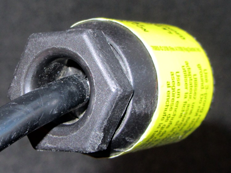
Driven by forces beyond my control, I had to rent a carpet cleaner from a local Big Box home repair store. The rugged line cord plug had an unusual (to me, anyway) strain relief fitting on the back, consisting of a circumferential clamp around the cord and a large diameter, deeply recessed opening on the nut to prevent the cord from flexing sharply:
AC Line Cord Plug – clamp nut
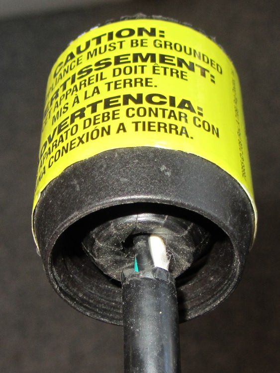
But something seemed odd, so I unscrewed the finger-tight clamping nut:
AC Line Cord Plug – clamp fingers
Whoever installed the cord cut the insulation back far too much, as those fingers should close on the insulation jacket, not the conductors.
I fought down my instinctive response, took a deep breath, clicked my heels together three times, repeated “This is not my problem”, and suddenly it wasn’t my problem any more. I tried reporting it to the harried clerk at the Big Box Store, but she instantly fluttered off to help somebody else after noting my return in the Big Book of Rental Contracts.
Suddenly a resonant thwup-thwup-thwup-thwup fills the house, but no helicoptersfill the skies; in fact, most of the noise seems to be inside the house and … it’s coming from the shop. We look at each other and dash toward the basement door, knowing perfectly well that this is the part of the movie where the audience chants “Don’t open the door!Don’t open the door!”
Come to find out that it’s the pair of old Harman-Kardon powered speakers attached to the PC attached to the Thing-O-Matic; the PC is off, but I left the speakers turned on. Quick diagnostics: turning the volume down doesn’t reduce the motorboating, pulling the audio cable out of the PC doesn’t change anything, the only cure is to turn them off.
Under normal circumstances, they’re pretty good-sounding speakers, at least to my deflicted ears, although I have my doubts about the effectiveness of that reflex port. I plugged in a pair of unpowered speakers as subwoofers down near the floor, just because they were lying around; a pair of 75 mm drivers does not a subwoofer make, fer shure.
Pop quiz: what’s wrong?
Need a hint? Looky here:
HK Powered Speakers – wall wart
Disassembly:
The front cloth grille has four snap mount posts, two secured by hot-melt glue blobs: pry harder than you think necessary
Two screws near the top of the bezel thus revealed hold it to the back
The bottom two screws holding the driver frame in place also hold the bezel to the back
Remove two screws from the grooves in the bottom of the back
Amazingly, the driver has two different size quick-disconnect tabs; the neatly polarized wires slide right off
Cut the audio cable just behind the back panel, then push the two-piece cable clamp outward from the inside:
HK Powered Speakers – cable grommet
The bottom of the circuit board shows considerable attention to detail. Note the excellent single-point ground at the negative terminal of the big filter capacitor:
HK Powered Speakers – PCB foil side
And, of course, that’s the problem: most of the electrolytic capacitors were dried out. My ESR tester reported the big filter cap (downstream of the bridge rectifiers) as Open and several of the smaller caps were around 10 Ω. Replacing them with similarly sized caps from the heap solved the problem.
The hard-floor brush for our old Samsung VAC-9048R vacuum cleaner began scratching the hardwood floor, which called for some investigation & repair. The Fine Manual doesn’t even mention the hard floor brush, so it’s obvious I’m on my own (as is usually the case). Believe it or not, we actually discussed buying a vacuum cleaner, but the new ones have poor reviews, bulky & awkward plastic widgets on the handle, or suffer from other glaringly obvious faults; although this one is aging poorly, it’s at least workable. Plus, I bought a lifetime supply of bags when it was new and it’s not dead yet.
So, we begin…
The rollers that used to support the front of the brush have worn down, allowing the bottom cover to erode on the floor. The right side ran through something sticky in the recent past:
Samsung 9048 – worn roller – right
The left side may not be sticky, but it’s in no better shape:
Samsung 9048 – worn roller – left
Remove the two obvious screws, pry the front edge up, and the whole cover plate pops off to reveal the two rollers. They pull straight out of the shaft support brackets molded into the top frame. Even their metal shafts show grievous wear:
Samsung 9048 – worn roller parts
The rollers consist of a hard plastic hub supporting a flexible rubbery tire, turning on a 3 mm steel shaft that’s worn on one side (which was downward, of course). The central holes in the rollers probably used to fit the shafts, but they’re now worn to 4 mm ID. The tires were probably a lot larger in diameter, too, back when they were new.
A bit of rummaging in the Basement Laboratory Warehouse Wing produced a bag of vibration isolation bushings that had about the right consistency to become tires:
Samsung 9048 – rollers and surplus vibration isolation bushings
They’re much larger than necessary, but are now, shall we say, fully depreciated and ready for a new, if somewhat downsized, lifestyle.
Unfortunately, they don’t fit onto the existing hubs, so I can’t use the hubs as a template. Fortunately, I have a lathe and some random nylon stock (with crosswise notches that didn’t pose much of a problem):
Samsun 9048 – turning roller hub
I came to my senses before converting this into a 3D printer project. If I had to make more than two hubs, it’d be a good idea to solid-model and print them, even if they’re just barely large enough to allow solid infill:
Samsun 9048 – finished roller hub
I’d go for a 3 mm ID to increase the wall width; these have a 4 mm ID to fit the brass bushings described below. There’s no significant overhang and they’d print with no problems. Maybe next time?
The isolation bushings cut easily with a sharp razor knife, so I pared them down to a bit over what I estimated to be the finished roller OD and width:
Samsung 9048 – roller tire before grinding
The 10-32 screw in that shiny new hub serves as an arbor in the lathe, where I held a Dremel tool with a sanding drum down on the compound rest, ran the lathe at its slowest back-gear speed, and sanded the bushing down to what seemed to be the right OD for the tire:
Samsung 9048 – grinding roller tire
The white snout in front leads to a shopvac that caught most of the dust. The front of the lathe chuck shows it wasn’t perfectly effective and I should have worn a dust mask; my glasses didn’t collect much dust, so maybe my lungs didn’t, either.
A trial fit in the floor brush body showed that this one was slightly too large and the sides needed tapering. The inside view:
Samsung 9048 – ground roller before side trim
The outside view, with the cover just slightly unable to snap closed:
Samsung 9048 – slightly oversize roller in place
Grinding a bit more off produced a pair of 15.5 mm OD tires which fit nicely. Some careful razor knife work smoothed and tapered the sides:
Samsung 9048 – finished rollers
Brass tubes (from the stash of cutoffs) compensate for the flat on the severely worn steel shafts; a fix that turned out to be much easier than building new shafts:
Samsung 9048 – roller shaft bushing hub
Then reassemble in reverse order and it’s all good!
I wrapped a layer of silicone tape around the large and slightly worn hard-plastic rear tires, even though I’m sure that won’t last very long at all:
Samsung 9048 – repaired hard floor brush – bottom
The shop doodle giving all the sizes:
Samsung 9048 – Roller dimension doodles
Now, if that doesn’t count as a gonzo repair, I don’t know what would… [grin]