The Smell of Molten Projects in the Morning

Ed Nisley's Blog: Shop notes, electronics, firmware, machinery, 3D printing, laser cuttery, and curiosities. Contents: 100% human thinking, 0% AI slop.

Category: Machine Shop

Mechanical widgetry

  • LED + Photodiode Test Fixture

    An upcoming Circuit Cellar column calls for a way to measure LED light output vs. current input, which means I need some way to hold LEDs directly over a photodiode while excluding ambient light. Fortunately, the M2 had black PLA filament already loaded:

    LED Photocell Fixture - parts
    LED Photocell Fixture – parts

    That honkin’ big photodiode is a surplus PIN-10AP that’s been lying in wait for an opportunity just like this. The green filter matches the silicon response to CIE-standard human eye sensitivity, so the output tracks what you’d actually see. That’s irrelevant for testing red LEDs that all have pretty much the same wavelength, but it might come in handy for something.

    The main body of the fixture holds the LED about 1 mm from the front of the photodiode, indexed against the LED flange so they’re all at a consistent location. The cap has three locating pins made of 3 mm orange filament, with black foam rubber to push the LED into position and block ambient light.

    The business end looks like this:

    LED Photocell Fixture - LED view
    LED Photocell Fixture – LED view

    The most convenient way to mount the thing involves a right-angle BNC adapter in my trusty bench vise:

    LED Photocell Fixture - with breadboard
    LED Photocell Fixture – with breadboard

    The circuitry has a voltage-to-current driver for the LED and a zero-bias current-to-voltage converter for the photocell. The zero-bias trick keeps the voltage across the photodiode at zero, so the current varies linearly with illumination.

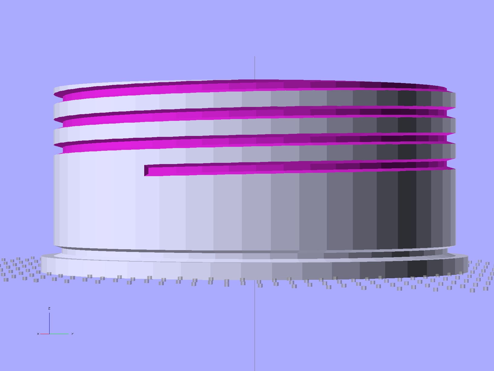
    The solid model laid out for printing along the X axis:

    LED Fixture for PIN-10AP Photodiode - solid model overview
    LED Fixture for PIN-10AP Photodiode – solid model overview

    It obviously has some improvements over the as-printed one in the pictures, in the unlikely event I need another fixture. The most important: a rear ring covering the back of the photodiode. Turns out that the PIN-10AP filter cap leaks a surprising amount of light around the body; I covered the gap with black tape to make the measurements, but that’s crude.

    I added a few screw holes to hold the parts together, but the cap (with the foam and pegs) must come off easily while swapping LEDs. I’d be tempted to sink studs into the body and use wing nuts to hold the lid in place, but I don’t have any 4-40 wing nuts…

    There’s a tiny bit of support under the central hole to support the LED flange recess and the trench for some foam under the leads:

    LED Fixture for PIN-10AP Photodiode - support
    LED Fixture for PIN-10AP Photodiode – support

    That’s another improvement; the as-printed one has foam on only one side of the leads.

    The OpenSCAD source code:

    // LED test fixture for PIN-10AP photodiode
    // Ed Nisley KE4ZNU May 2013
    
    // Layouts: Adapter AdapterSupport Cap Shield Build Show
    
    Layout = "Build";
    
    Gap = 8;		// between parts in Show
    
    //- Extrusion parameters must match reality!
    //  Print with +1 shells and 3 solid layers
    
    ThreadThick = 0.25;
    ThreadWidth = 0.40;
    
    HoleWindage = 0.2;
    
    function IntegerMultiple(Size,Unit) = Unit * ceil(Size / Unit);
    
    Protrusion = 0.1;			// make holes end cleanly
    
    Spacing = 5;				// between parts on build platform
    
    inch = 25.4;
    
    Tap2_56 = 0.070 * inch;
    Clear2_56 = 0.082 * inch;
    Head2_56 = 0.156 * inch;
    Head2_56Thick = 0.055 * inch;
    
    //----------------------
    // Dimensions
    
    PhotoDiodeOD = 31.3;
    PhotoDiodeStemOD = 16.0;
    PhotoDiodeStemLength = 8.0;
    PhotoDiodeWindowDia = 17.7;
    PhotoDiodeHeight = 14.0;
    
    FixtureOD = PhotoDiodeOD + 2*7.0;
    
    LEDDia = 5.0;				// LED body
    LEDFlangeOD = 6.0;			// flange at base of LED
    LEDFlangeThick = IntegerMultiple(1.5,ThreadThick);
    LEDLength = 10.0;			// overall length
    LEDRecess = 4.0;			// tube to fit LED body
    LEDSides = 8;
    
    FixtureLength = PhotoDiodeHeight + LEDLength + IntegerMultiple(1.0,ThreadThick);
    
    CapLength = 15.0;			// LED cover
    
    FoamOD = FixtureOD/2;
    FoamThick = IntegerMultiple(2.0,ThreadThick);
    
    TrenchDepth = 2*FoamThick;
    TrenchWidth = LEDDia;
    
    ShieldThick = 5.0;
    ShieldScrewCircle = PhotoDiodeOD + (FixtureOD - PhotoDiodeOD)/2;
    
    PinOD = 3.0;				// alignment pin (filament)
    PinLength = 10.0;			//   ... total length
    PinCircle = FixtureOD/2;
    
    GrubScrewOD = Tap2_56;
    
    $fn=4*6;					// default cylinder sides
    
    //----------------------
    // Useful routines
    
    module PolyCyl(Dia,Height,ForceSides=0) {			// based on nophead's polyholes
    
      Sides = (ForceSides != 0) ? ForceSides : (ceil(Dia) + 2);
    
      FixDia = Dia / cos(180/Sides);
    
      cylinder(r=(FixDia + HoleWindage)/2,
               h=Height,
    	   $fn=Sides);
    }
    
    module ShowPegGrid(Space = 10.0,Size = 1.0) {
    
      RangeX = floor(95 / Space);
      RangeY = floor(125 / Space);
    
    	for (x=[-RangeX:RangeX])
    	  for (y=[-RangeY:RangeY])
    		translate([x*Space,y*Space,Size/2])
    		  %cube(Size,center=true);
    
    }
    
    //-----------------------
    // Parts
    
    module Adapter() {
    
    	difference() {
    		cylinder(r=FixtureOD/2,h=FixtureLength);
    		translate([0,0,-Protrusion]) {
    			PolyCyl(LEDDia,2*FixtureLength,LEDSides);
    			PolyCyl(PhotoDiodeWindowDia,(FixtureLength - LEDRecess + Protrusion));
    			PolyCyl(PhotoDiodeOD,(PhotoDiodeHeight + Protrusion));
    		}
    		translate([0,0,(FixtureLength - LEDFlangeThick)])
    			PolyCyl(LEDFlangeOD,2*LEDFlangeThick,LEDSides);
    		translate([FixtureOD/2,0,(FixtureLength + FoamThick/2 - LEDFlangeThick)]) {
    			cube([FixtureOD,TrenchWidth,FoamThick],center=true);
    		}
    		for (angle = [90:90:270])
    			rotate(angle)
    				translate([0.75*PinCircle,0,(FixtureLength - PinLength/2)])
    					PolyCyl(PinOD,PinLength,6);
    		for (angle = [0:120:240])
    			rotate(angle)
    				translate([ShieldScrewCircle/2,0,-Protrusion])
    					rotate(45)
    						PolyCyl(Tap2_56,(ShieldThick - 6*ThreadThick + Protrusion));
    		if (0)
    			translate([0,0,FixtureLength/4])
    				rotate([0,90,0])
    					PolyCyl(GrubScrewOD,FixtureOD);
    	}
    
    }
    
    module AdapterSupport() {
    
    spiderthick = IntegerMultiple(LEDFlangeThick - ThreadThick,ThreadThick);
    
    	color("Yellow")
    		union() {
    			for (leg = [0:LEDSides/2 - 1])
    				rotate(leg*360/LEDSides)
    					translate([0,0,spiderthick/2])
    					cube([(LEDFlangeOD - 0.5*ThreadWidth),
    							2.5*ThreadWidth,
    							spiderthick],
    							center=true);
    			cylinder(r=LEDDia/2,h=spiderthick,$fn=LEDSides);
    			for (bar = [-1:1])
    				translate([LEDDia/3,(bar*3*ThreadWidth - ThreadWidth),0])
    					cube([FixtureOD/2,2*ThreadWidth,IntegerMultiple(LEDFlangeThick - ThreadThick)]);
    		}
    }
    
    module Cap() {
    
    	difference() {
    		cylinder(r=FixtureOD/2,h=CapLength);
    		translate([(FixtureOD/2 - LEDDia/2),0,CapLength]) {
    			cube([FixtureOD,TrenchWidth,2*TrenchDepth],center=true);
    		}
    		translate([0,0,(CapLength - FoamThick)])
    			PolyCyl(FoamOD,(FoamThick + Protrusion));
    		for (angle = [90:90:270])
    			rotate(angle)
    				translate([0.75*PinCircle,0,(CapLength - PinLength/2)])
    					PolyCyl(PinOD,PinLength,6);
    	}
    
    }
    
    module Shield() {
    
    	difference() {
    		cylinder(r=FixtureOD/2,h=ShieldThick);
    		translate([0,0,-Protrusion])
    			PolyCyl(PhotoDiodeStemOD,(ShieldThick + 2*Protrusion));
    		for (angle = [0:120:240])
    			rotate(angle) {
    				translate([ShieldScrewCircle/2,0,-Protrusion])
    					rotate(180/5)
    						PolyCyl(Clear2_56,(ShieldThick + 2*Protrusion));
    				if (0)
    				translate([ShieldScrewCircle/2,0,(ShieldThick - 1.5*Head2_56Thick)])
    					rotate(180/6)
    						PolyCyl(Head2_56,4*Head2_56Thick);
    			}
    	}
    }
    
    //-------------------
    // Build it...
    
    ShowPegGrid();
    
    if (Layout == "Adapter")
    	Adapter();
    
    if (Layout == "Cap")
    	Cap();
    
    if (Layout == "Shield")
    	Shield();
    
    if (Layout == "Show") {
    	translate([0,0,(ShieldThick + Gap)]) {
    		translate([0,0,FixtureLength + CapLength + Gap])
    			rotate([180,0,0])
    				Cap();
    		Adapter();
    
    		color("Orange")
    		for (angle = [90:90:270])
    			rotate(angle)
    				translate([0.75*PinCircle,0,(FixtureLength + Gap - PinLength/2)])
    					PolyCyl(PinOD,PinLength,6);
    	}
    
    	Shield();
    }
    
    	if (Layout == "AdapterSupport") {
    	translate([0,0,FixtureLength])
    		rotate([180,0,0])
    			%Adapter();
    	AdapterSupport();
    }
    
    if (Layout == "Build") {
    	translate([(Spacing + FixtureOD),0,0]) {
    		translate([0,0,FixtureLength])
    			rotate([180,0,0])
    				Adapter();
    		AdapterSupport();
    	}
    	translate([0,0,0])
    		Cap();
    
    	translate([-(Spacing + FixtureOD),0,0])
    		Shield();
    }
    
  • Makergear M2: Extruder Thermistor Recalibration

    Those measurements suggested that my initial correction to the Table 1 values weren’t quite correct, but a similar correction might work as long as I didn’t change the insulating wrap. This graph includes a linear fit to the Nozzle TC data, based on the original M2 firmware’s Table 1 thermistor data and cotton insulation:

    M2 Extruder Thermistor Recal - Table 1 Insulated - Nozzle TC linear fit
    M2 Extruder Thermistor Recal – Table 1 Insulated – Nozzle TC linear fit

    Applying that equation to Table 1 produces this thermistor lookup table:

    #if (THERMISTORHEATER_0 == 8) || (THERMISTORHEATER_1 == 8) || (THERMISTORHEATER_2 == 8) || (THERMISTORBED == 8) // M2 thermistors on RAMBO
    const short temptable_8[][2] PROGMEM = {
    	{23*OVERSAMPLENR, 243},
    	{25*OVERSAMPLENR, 239},
    	{27*OVERSAMPLENR, 235},
    	{28*OVERSAMPLENR, 231},
    	{31*OVERSAMPLENR, 227},
    	{33*OVERSAMPLENR, 223},
    	{35*OVERSAMPLENR, 219},
    	{38*OVERSAMPLENR, 215},
    	{41*OVERSAMPLENR, 211},
    	{44*OVERSAMPLENR, 207},
    	{48*OVERSAMPLENR, 203},
    	{52*OVERSAMPLENR, 199},
    	{56*OVERSAMPLENR, 195},
    	{61*OVERSAMPLENR, 191},
    	{66*OVERSAMPLENR, 187},
    	{71*OVERSAMPLENR, 183},
    	{78*OVERSAMPLENR, 179},
    	{84*OVERSAMPLENR, 175},
    	{92*OVERSAMPLENR, 171},
    	{100*OVERSAMPLENR, 167},
    	{109*OVERSAMPLENR, 163},
    	{120*OVERSAMPLENR, 159},
    	{131*OVERSAMPLENR, 155},
    	{143*OVERSAMPLENR, 151},
    	{156*OVERSAMPLENR, 147},
    	{171*OVERSAMPLENR, 143},
    	{187*OVERSAMPLENR, 139},
    	{205*OVERSAMPLENR, 135},
    	{224*OVERSAMPLENR, 131},
    	{245*OVERSAMPLENR, 127},
    	{268*OVERSAMPLENR, 123},
    	{293*OVERSAMPLENR, 119},
    	{320*OVERSAMPLENR, 115},
    	{348*OVERSAMPLENR, 111},
    	{379*OVERSAMPLENR, 107},
    	{411*OVERSAMPLENR, 103},
    	{445*OVERSAMPLENR, 99},
    	{480*OVERSAMPLENR, 95},
    	{516*OVERSAMPLENR, 91},
    	{553*OVERSAMPLENR, 87},
    	{591*OVERSAMPLENR, 83},
    	{628*OVERSAMPLENR, 79},
    	{665*OVERSAMPLENR, 75},
    	{702*OVERSAMPLENR, 71},
    	{737*OVERSAMPLENR, 67},
    	{770*OVERSAMPLENR, 63},
    	{801*OVERSAMPLENR, 59},
    	{830*OVERSAMPLENR, 55},
    	{857*OVERSAMPLENR, 51},
    	{881*OVERSAMPLENR, 47},
    	{903*OVERSAMPLENR, 43},
    	{922*OVERSAMPLENR, 39},
    	{939*OVERSAMPLENR, 35},
    	{954*OVERSAMPLENR, 31},
    	{966*OVERSAMPLENR, 27},
    	{977*OVERSAMPLENR, 23},
    	{985*OVERSAMPLENR, 19},
    	{993*OVERSAMPLENR, 15},
    	{999*OVERSAMPLENR, 11},
    	{1004*OVERSAMPLENR, 7},
    	{1008*OVERSAMPLENR, 3},
    	{1011*OVERSAMPLENR, 0}
    };
    #endif
    

    I extrapolated the last entry from the previous two, because if the table doesn’t include an entry for 0 °C, then when you turn the heater off, the setpoint winds up being the lowest temperature greater than zero. Doesn’t make any difference, I think, but looks odd.

    Load that table, run the temperature up, record more data:

    M2 Extruder Thermistor Recal - slope-offset fit from Table 1
    M2 Extruder Thermistor Recal – slope-offset fit from Table 1

    The error isn’t particularly pretty, being off by +4 °C at the high end. You could hand-tweak the linear fit equation to push the error down at normal operating temperatures, but it’s close enough for my purposes.

    Although I don’t have any numbers, one benefit of tighter thermal coupling to the extruder nozzle is greatly reduced overshoot during heating.

  • Makergear M2: Hot End Temperature Profiles

    Knowing that all the thermocouples and amps and meters report more-or-less the same values, I tucked several of them around the hot end:

    M2 Hot End Temperature Profile - Insulated
    M2 Hot End Temperature Profile – Insulated

    Their IDs and placement:

    • Nozzle TM – Makergear thermistor epoxied to nozzle
    • Nozzle TC – thermocouple epoxied to nozzle
    • Heater – thermocouple at heater, under insulating sleeve
    • Sleeve – thermocouple at heater, outside insulating sleeve
    • Surface – thermocouple taped to outside of cotton insulation

    Although I intended to put the Heater thermocouple bead  on the ceramic heater itself, I have no way of knowing exactly where it was, nor whether it actually made good contact with the heater body, because it’s tucked inside the fiberglass + silicone insulating sleeve. That sleeve will, perforce, be somewhat cooler than the heater, and that will certainly affect the results.

    The sensors are stacked more-or-less radially outward from the center, which may or may not make any difference.

    The upper fan (which runs constantly) does not blow directly on the leads, but air flow over the leads does change the reported temperatures: I haven’t taken that into account, even though it’s certainly significant, but the leads and fan remain in (approximately) the same position for the tests.

    In the stock M2, the lower fan blows directly on the uninsulated hot end, the thermistor, and the nozzle; the G-Code controls when it’s turned on, so whatever effects it has are not constant. It was always off for these tests, but that’s certainly not the case while printing an object.

    The cotton insulation wrap isn’t the same as I used earlier; it was easier to use a new length of cloth than to remove the Kapton tape from the old insulation. The new insulation was slightly thicker, as well, and did a better job of reducing heat loss. I took the Insulated measurements first, then removed the cloth for the Bare measurements. Although I tried to keep the thermocouples in the same positions, I certainly nudged the wires while peeling off the cloth:

    M2 Hot End Temperature Profile - Bare
    M2 Hot End Temperature Profile – Bare

    The Marlin firmware in the M2 normally uses thermistor Table 1. I adjusted those values to create Table 8, which exactly corrected the mismatch, at least with the earlier, thinner insulation.

    After each temperature step, I waited until the temperature plot in the Pronterface graph had settled to a single pixel line for one minute. That didn’t mean the temperature was exactly at the setpoint, but it wasn’t changing very much at all, which is all I needed for this dataset.

    Keeping all that in mind…

    Graph 1 — Thermistor Table 1, bare (the as-shipped M2 configuration):

    Hot End Temperature Profile Graph - Table 1 - Bare
    Hot End Temperature Profile Graph – Table 1 – Bare

    Graph 2 — Thermistor Table 1, with insulation:

    Hot End Temperature Profile Graph - Table 1 - Insulated
    Hot End Temperature Profile Graph – Table 1 – Insulated

    Graph 3 — Thermistor Table 8, bare:

    Hot End Temperature Profile Graph - Table 8 - Bare
    Hot End Temperature Profile Graph – Table 8 – Bare

    Graph 4 — Thermistor Table 8, with insulation:

    Hot End Temperature Profile Graph - Table 8 - Insulated
    Hot End Temperature Profile Graph – Table 8 – Insulated

    The data in Graph 4 clearly show that the correction factor I used to create Table 8 doesn’t apply with a different insulation wrap around the hot end. Although the Nozzle TM and Nozzle TC lines are quite close, they aren’t the exact match I saw before.

    When you compare Graph 1 with Graph 3, then Graph 2 with Graph 4, you’ll see that the thermocouple data remains consistent: the temperature differences at a specific temperature are the same, regardless of what the Nozzle TM indicates. For example, at the upper-right corner of Graph 1, when the Nozzle TM reports 175 °C, Nozzle TC is at 145 °C and the Heater is at 124 °C (use the Y axis values): Nozzle TC is 21 °C higher than the Heater. Looking in Graph 3 to the point where the Heater is 124 °C, the Heater is once again 21 °C hotter (again, using the Y axis values).

    Although it seems odd, having the thermocouple on the bare Heater run cooler than the Nozzle TC is entirely possible, because the Heater thermocouple is in contact with the relatively thin sleeve, which is cooling the outside of the heater core. The Nozzle TC has a direct metallic + epoxy connection to the inside of the heater core, which will be hotter than its exterior surface.

    Conversely, Graph 2 shows the insulated Heater running hotter than the Nozzle TM. That also makes sense: with less heat loss through the Sleeve, the exterior of the heater gets hotter than the threaded brass cylinder in the middle, which is losing heat at both ends.

    Those correlations suggest the various thermocouples do indicate the actual temperatures and the nozzle thermistor doesn’t.

    I believe bonding the thermistor to the nozzle with epoxy doesn’t affect that conclusion. It does make the results less subject to random changes due to the thermistor bead’s exact position and contact with the nozzle, though, and certainly makes the temperatures I record quite different from those found in other M2 hot ends. The fundamental rule here is that when you want to measure the temperature of something, the probe must make solid contact with the something, not dangle in mid-air somewhere nearby.

    Based on some earlier (and rather crude) measurements, I proposed that the thermistor was gaining heat through its leads, because they pass over the heater core. That’s definitely not true, as the Nozzle TM and Nozzle TC have the same temperature difference between the bare and insulated cases: compare Graph 1 with Graph 2, then Graph 3 with Graph 4. If the thermistor gained heat, it would be relatively hotter than the thermocouple in the case with additional insulation, because the Heater would then run hotter and pipe more heat into the thermistor leads.

    That’s why you make measurements…

    Along those lines, I’ve asked several people I trust to measure their M2 hot ends [You know who you are. Thanks!] and the results are unequivocal: nobody sees any significant variation between the thermistor and a thermocouple tucked beside it. The only difference in the setups seems to be the solid connection between my sensors and the nozzle. I can’t explain it, either, and I’ve shot down several of my own proposals.

  • Capping a Sink Drain Pipe

    We put the new furnace (replacing the old one) closer to the wall with the flue pipe, displacing an ancient slop sink (which vanished from the end of the driveway in about an hour) in the process. I “plugged” the drain with a twist of paper towel until the installation was done:

    Corroded sink drain nut
    Corroded sink drain nut

    The overexposed blue-hot glow comes from the LED worklight on the right.

    Despite being chrome-plated brass, the nut at the base of that vertical chrome pipe was firmly corroded to the short nipple emerging from the iron tee. After a few minutes of fruitless wrenching, I deployed a Dremel cutting wheel, slit the nut, gave it a shot with a chisel, and it popped loose. A rubber cap clamped around the nipple finished the job:

    Sealed sink drain pipe with split nut
    Sealed sink drain pipe with split nut

    Next case!

  • Arduino Leonardo + TC4 Thermocouple Shield + TC4 Server

    Because I want to measure several fairly high temperatures in and around the extruder with the LinuxCNC controller for the M2, I need a multi-channel thermocouple input. LinuxCNC’s hal_input interface module exposes the values produced by USB HID peripherals as HAL pins, which seems to be a nice way to add devices. A bit of searching revealed the TC4 Arduino Shield four-channel thermocouple + four-channel thermistor + assorted I/O board produced by the homeroasters.org folks as part of their DIY coffee roast controller.

    The gotcha: ordinary Arduino boards cannot (without extraordinary effort) become USB HID peripherals, as their USB interface works only as a serial data device. The solution: the new-ish Arduino Leonardo has an on-chip USB interface that can act as a USB HID peripheral as well as the usual serial device.

    Dan Newman, of Sailfish firmware fame, conjured up an a Arduino program (which, IMO, is far more complex than a mere sketch) that provides both a human-readable terminal interface and a LinuxCNC HAL-compatible USB HID interface using the Leonardo’s USB capabilities; the TC4Server project repository is on my GitHub account to keep it close to all the other stuff that should appear over the course of this project. His firmware builds on the libraries for the homeroaster’s tc4-shield Google Code project, but is intended for use with LinuxCNC, rather than as part of an Arduino controller.

    It’s worth noting that the Leonardo has a mere 32 kB of program storage, so the extensive help documentation built into the program helped prevent feature creep.

    Although I’m not yet using LinuxCNC with the M2, I can use TC4-Server’s serial terminal interface to read four channels of thermocouple data to help figure out what’s going on with the M2’s extruder thermistor. The TC4 shield has screw terminals for the thermocouples, but I also added a Proto ScrewShield board for thermistor resistors and easier connections:

    TC4 on ProtoScrewShield on Leonardo
    TC4 on ProtoScrewShield on Leonardo

    The TC4 Shield PCB layout assumes it’s being used with the original Arduino series of boards that bring the I2C (aka I2C, IIC, etc) SDA and SCL signals out on the A4 and A5 analog input pins, respectively. The newer Leonardo board brings SDA and SCL out in a separate header, so you must hotwire them across the board. The green and blue wires (stripped from a ribbon cable) accomplish that purpose: they’re plugged into the new Leonardo header through bent male header pins and clamped into the ScrewShield terminals. This assumes the Leonardo’s A4 and A5 pins remain as inputs, which is true for Dan’s firmware. If you actually need those pins for analog inputs, then you must remove the header pins that interconnect the boards and hotwire directly to the TC4 headers.

    The TC4 shield includes an on-board temperature sensor that serves as the thermocouple cold-junction compensation reference. In my simple tests, the board has about 1 °C of self-heating, so I also use it to report the ambient temperature.

    With all that in hand, I connected the thermocouple epoxied to the M2’s nozzle to the TC4 and re-ran the previous test with the modified thermistor table:

    Rescaled extruder - thermocouple in TC4 board
    Rescaled extruder – thermocouple in TC4 board

    The TC4 shield produces the same result as the Fluke meter with the same thermocouple, so we know those results will be consistent.

    The modified thermistor table produces results that overlay thermocouple data. The questions come down to the accuracy of the thermocouple and whether bending the thermistor table actually represents an inherent property of the thermistor or just compensates for another problem.

    Part of my motivation for using thermocouples, rather than thermistors, is that thermocouples avoid the whole dance of matching a given thermistor with a set of properties. Given the uncertain provenance of most thermistors, I have no reason to believe any of them match their alleged datasheets…

  • Makergear M2: Thermistor vs. Thermocouple

    With the stock thermistor and my added thermocouple epoxied to the M2’s nozzle, I stepped the temperature upward, let it settle, and recorded the temperature from the Pronterface status display and my Fluke thermocouple meter:

    First Heat - M2 thermistor - Fluke with thermocouple
    First Heat – M2 thermistor – Fluke with thermocouple

    Because the firmware servos the temperature through the stock thermistor, that line is dead straight at the exact setpoint values: the reference never disagrees with itself. The thermocouple, however, reads low by about 12%: according to it, the nozzle runs much cooler than the thermistor value.

    Huh?

    Several explanations come to mind:

    • The firmware is using a lookup table that doesn’t match the thermistor
    • The Fluke thermocouple meter reports the wrong value
    • The thermocouple junction is defective
    • Despite the epoxy blob, the two sensors aren’t at the same temperature
    • Something else is kaflooie

    This obviously calls for more data…

  • Makergear M2: Nozzle Temperature Sensing

    The stock Makergear M2 hot end uses a 100 kΩ thermistor for temperature sensing. A wrap of Kapton tape holds it against the brass nozzle, with a stretchy fiberglass-lined tube for protective insulation and a bit of pressure. This picture shows the tape pocket around the thermistor, with my thumbnail on the left:

    M2 Nozzle Thermistor - as-shipped
    M2 Nozzle Thermistor – as-shipped

    Peeling back the tape a bit shows the thermistor against the nozzle, with the glass bead reflecting the LED ringlight around the macro lens adapter:

    M2 Nozzle thermistor - exposed
    M2 Nozzle thermistor – exposed

    The RAMBo board in the M2 has four thermistor inputs and no thermocouple inputs, which surely drove the decision to use themistors. I want to use thermocouples with the LinuxCNC controller, because they’re more compact and happier at higher temperatures.

    So I unwrapped the nozzle and lined up a thermocouple beside the thermistor:

    M2 - extruder - thermistor-thermocouple
    M2 – extruder – thermistor-thermocouple

    Where a dab of JB Weld firmly bonds them to the nozzle:

    M2 - extruder - epoxied sensors
    M2 – extruder – epoxied sensors

    As nearly as I can tell, the JB Weld that I used on the Thing-O-Matic is still going strong. I think the trick is to not apply mechanical force to the bond when it’s hot; secure the leads firmly and use the epoxy only as a thermal connection. Yes, you can get fancy higher-temperature adhesives, but this seems to work well enough.

    For the moment, I’m using ordinary cotton cloth secured with Kapton tape as insulation:

    M2 - extruder - cotton insulation
    M2 – extruder – cotton insulation

    The brown dot that looks like a bead is actually a flat stain on the nozzle.

    The insulation should become something more suited for high temperatures, perhaps the ceramic fiber I used on the Thing-O-Matic, but cotton will suffice for now.

    Now, wisely is it written that a man with one thermometer knows the temperature, while a man with two thermometers is never certain…