Ed Nisley's Blog: Shop notes, electronics, firmware, machinery, 3D printing, laser cuttery, and curiosities. Contents: 100% human thinking, 0% AI slop.
Strange though it may seem, the kitchen faucet handle broke while Mary was using it. The rear wall of the socket that fits over the cartridge valve stem fractured:
American Standard Faucet Handle – broken mount
Having no water in the kitchen is not to be tolerated, so I applied a redneck fix while pondering the problem:
Kitchen Faucet – redneck handle repair
Based on that comment, I called the American Standard hotline (800-442-1920), described the situation, and they’re sending a replacement handle and cartridge. Evidently the new handle won’t fit the old cartridge, which makes me feel better about not stockpiling repair parts, even while I now wonder what the new cartridge part number might be and how you’d tell them apart.
Anyhow, the redneck fix wouldn’t suffice for the next week; I needed something slightly more permanent. The broken wall fit neatly in place on the mount, but:
It must withstand far more force than a simple glue joint can provide
I can’t machine square holes
Wrapping a metal sleeve around the mount seemed like too much work
You undoubtedly saw this coming a while ago:
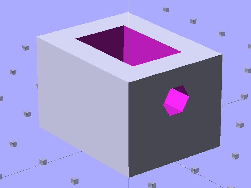
Am Std Faucet Handle Sleeve – solid model
The mount tapers slightly from the handle body toward the open end to provide draft for the molding process. I applied a hull() operator to two thin rectangles spaced the right distance apart along the Z axis to create a positive model of the mount, which then gets subtracted from the blocky outer rectangle. The hole clears a 10-32 screw that fits the standard setscrew threads (normally hidden behind the handle’s red-and-blue button).
Unlike most printed parts I’ve done recently, the sleeve suffered from severe shrinkage along the outside walls:
Faucet handle sleeve – build distortion
The inside maintained the right shape, so I cleared the nubs with a file and pressed it in place around the mount with the rear wall snapped into position. The black plastic socket evidently isolates the handle from the valve stem and I used a stainless 10-32 screw to prevent the nightmare scenario of having the sleeve slide downward along the tapered mount and block the setscrew. Overall, it came out fine:
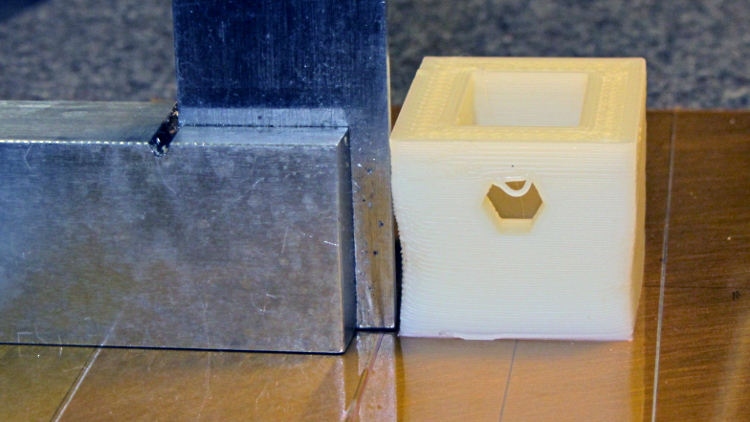
American Standard faucet handle – compression sleeve
However, the chunky sleeve didn’t clear the opening in the escutcheon cap, which put the cap on the windowsill for the next week. The result works much better than the redneck fix and looks almost presentable. It’s certainly less conspicuous:
American Standard faucet handle – temporary repair
I hope the new handle has a much more robust socket…
The OpenSCAD source code:
// Quick fix for broken American Standard Elite 4454 faucet handle
// Ed Nisley KE4ZNU February 2013

//- Extrusion parameters must match reality!
//  Print with +2 shells and 3 solid layers

ThreadThick = 0.25;
ThreadWidth = 2.0 * ThreadThick;

HoleFinagle = 0.4;
HoleFudge = 1.00;

function IntegerMultiple(Size,Unit) = Unit * ceil(Size / Unit);
function HoleAdjust(Diameter) = HoleFudge*Diameter + HoleFinagle;

Protrusion = 0.1;           // make holes end cleanly

//----------------------
// Dimensions

Wall = 5.0;

Slice = ThreadThick;                // minimal thickness for hull object

ShaftEnd = [11.6,17.8,Slice];
ShaftBase = [12.1,18.8,Slice];
ShaftLength = 19.0;

Block = [(ShaftBase[0] + 2*Wall),(ShaftBase[1] + 2*Wall),ShaftLength - Protrusion];

ScrewOffset = 6.5;          // from End
ScrewDia = 5.0;             // clearance

//----------------------
// Useful routines

module ShowPegGrid(Space = 10.0,Size = 1.0) {

    Range = floor(50 / Space);

    for (x=[-Range:Range])
        for (y=[-Range:Range])
            translate([x*Space,y*Space,Size/2])
            %cube(Size,center=true);

}

module PolyCyl(Dia,Height,ForceSides=0) {           // based on nophead's polyholes
  Sides = (ForceSides != 0) ? ForceSides : (ceil(Dia) + 2);
  FixDia = Dia / cos(180/Sides);
  cylinder(r=HoleAdjust(FixDia)/2,h=Height,$fn=Sides);
}

//----------------------
// Model the handle's tapered shaft

module Shaft() {

    hull() {
        translate([0,0,ShaftLength - Slice/2])
            cube(ShaftEnd, center=true);
        translate([0,0,Slice/2])
            cube(ShaftBase, center=true);
    }

}

//----------------------
// Build it!

ShowPegGrid();

difference() {
    translate([0,0,ShaftLength/2])
        cube(Block,center=true);
    Shaft();
    translate([0,0,ShaftLength - ScrewOffset])
        rotate([-90,0,0])
            PolyCyl(ScrewDia,ShaftBase[1],6);
}
A (formerly Belkin, now Razer, which is evidently unrelated to Mazer Rackham) Nostromo N52 SpeedPad might not be a perfect CNC pendant, but it does have plenty of buttons and an (oddly oriented) XY joypad that might be useful for, say, a 3D printer controller running LinuxCNC.
Belkin Nostromo N52 SpeedPad
Following the same path as with the Logitech Dual Action Gamepad that became the Joggy Thing, we find that the N52 reports itself as a keyboard and a mouse:
udevadm info --query=all --attribute-walk --name=/dev/bus/usb/002/004

Udevadm info starts with the device specified by the devpath and then
walks up the chain of parent devices. It prints for every device
found, all possible attributes in the udev rules key format.
A rule to match, can be composed by the attributes of the device
and the attributes from one single parent device.

  looking at device '/devices/pci0000:00/0000:00:02.0/usb2/2-10':
    KERNEL=="2-10"
    SUBSYSTEM=="usb"
    DRIVER=="usb"
    ATTR{configuration}==""
    ATTR{bNumInterfaces}==" 2"
    ATTR{bConfigurationValue}=="1"
    ATTR{bmAttributes}=="80"
    ATTR{bMaxPower}==" 90mA"
    ATTR{urbnum}=="1354"
    ATTR{idVendor}=="050d"
    ATTR{idProduct}=="0815"
    ATTR{bcdDevice}=="0210"
    ATTR{bDeviceClass}=="00"
    ATTR{bDeviceSubClass}=="00"
    ATTR{bDeviceProtocol}=="00"
    ATTR{bNumConfigurations}=="1"
    ATTR{bMaxPacketSize0}=="8"
    ATTR{speed}=="1.5"
    ATTR{busnum}=="2"
    ATTR{devnum}=="4"
    ATTR{version}==" 1.10"
    ATTR{maxchild}=="0"
    ATTR{quirks}=="0x0"
    ATTR{authorized}=="1"
    ATTR{manufacturer}=="Honey Bee "
    ATTR{product}=="Nostromo SpeedPad2 "

... snippage ...
Note the trailing blank in the manufacturer and product values.
Create a new rules file /etc/udev/rule/90-Nostromo.rules to change the group and permissions:
# Belkin Nostromo N52 SpeedPad controller for LinuxCNC
# Ed Nisley - KE4ZNU - February 2013

ATTRS{product}=="Nostromo SpeedPad2",GROUP="plugdev",MODE="0660"
Note that the file name must start with a number around 90- to avoid being clobbered by a rule in /lib/udev/rules.d/50-udev-default.rules that (re)sets the permissions to 0640; the doc suggests that rules without numbers happen after all the number rules, so perhaps you could just use meaningful names. That took an embarrassingly long time to figure out…
There’s no need for the trailing blank in that rule, as the match proceeds left-to-right and stops at the end of the test string.
You must, perforce, be in the plugdev group. If not, add yourself.
You need not unplug the N52 to test the rule. Just use:
The + prefix tells HAL to capture the named device and prevent its events from reaching X. The KRL codes suggest which functions you’re interested in for that particular device. The suffix digit selects successive devices for multiple gadgets matching the same name string.
Apparently, the N52 reports it can produce all the usual keyboard and mouse values & buttons, even if they’re not connected to physical hardware. I suspect it has generic keyboard / mouse controllers inside, with just a few of the usual matrix crosspoints connected to switches.
The basic key mapping, sorted by the Nostromo functions:
Type
Dir
Name
Nostromo key
bit
OUT
input.0.key-tab
F1
bit
OUT
input.0.key-q
F2
bit
OUT
input.0.key-w
F3
bit
OUT
input.0.key-e
F4
bit
OUT
input.0.key-r
F5
bit
OUT
input.0.key-capslock
F6
bit
OUT
input.0.key-a
F7
bit
OUT
input.0.key-s
F8
bit
OUT
input.0.key-d
F9
bit
OUT
input.0.key-f
F10
bit
OUT
input.0.key-leftshift
F11
bit
OUT
input.0.key-z
F12
bit
OUT
input.0.key-x
F13
bit
OUT
input.0.key-c
F14
bit
OUT
input.0.key-space
F15
bit
OUT
input.0.key-leftalt
Orange button
bit
OUT
input.0.key-right
Pad bottom
bit
OUT
input.0.key-down
Pad front
bit
OUT
input.0.key-up
Pad rear
bit
OUT
input.0.key-left
Pad top
bit
OUT
input.1.btn-middle
Wheel press
s32
OUT
input.1.rel-wheel-counts
Scroll wheel
bit
IN
input.1.led-numl
Red LED
bit
IN
input.1.led-capsl
Green LED
bit
IN
input.1.led-scrolll
Blue LED
The bit pins also have inverted values available on the corresponding -not pins. The LEDs have an -invert that flips the sense of the input pin. The rel-wheel pin has other useful tidbits as suffixes; the count changes by ±1 for each wheel detent.
The Tab key and all the letters auto-repeat, the various Shift and Alt keys do not. That seems to make no difference to the bit values reported by HAL.
For reasons that undoubtedly make sense to him, my buddy Aitch is moving to coastal NC. Seeing as how we lived in Raleigh for half a decade, I figure he needs some hints on how to blend in…
Toy cars up on blocks
The solid model looks about the way you’d expect:
Concrete block – solid model
The webs are slightly thinner than in real life, but it looks OK to me. The web came out slightly over 3 thread widths = 1.5 mm, to ensure they get a bit of fill rather than being two distinct threads. I originally tried making the web exactly 3 threads wide, which produced tiny dots of fill on the sides and corners. They printed with 0.20 infill; they’d print faster with 1.00 infill or all-solid layers.
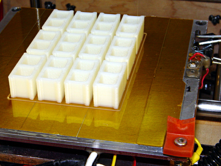
You’ll want to create a pile o’ blocks at once, of course, although this array took about two hours:
Concrete blocks – build platform
The OpenSCAD source code:
// Scale model concrete block
// Ed Nisley KE4ZNU February 2013

// Extrusion parameters must match reality!
// Print with +0 shells and 3 solid layers

ThreadThick = 0.25;
ThreadWidth = 2.0 * ThreadThick;

function IntegerMultiple(Size,Unit) = Unit * ceil(Size / Unit);

Protrusion = 0.1;           // make holes end cleanly

//----------------------
// Dimensions

Scale = (1/25) * (3*ThreadWidth);

BlockWidth = Scale * 190;
BlockLength = Scale * 390;
BlockHeight = BlockWidth;

WebWidth = Scale * 30;

CoreSize = [(BlockWidth - 2*WebWidth),(BlockLength - 4*WebWidth)/2,BlockHeight];

CornerRadius = WebWidth/2;

//----------------------
// Useful routines

module ShowPegGrid(Space = 10.0,Size = 1.0) {

    Range = floor(50 / Space);

    for (x=[-Range:Range])
        for (y=[-Range:Range])
            translate([x*Space,y*Space,Size/2])
            %cube(Size,center=true);

}

//-------------------
// Component parts

module Core(Size,Radius) {
    translate([0,0,(Size[2] - Protrusion)/2])
        minkowski() {
            cube([(Size[0] - 2*Radius),(Size[1] - 2*Radius),Size[2]],center=true);
            cylinder(r=Radius,h=Protrusion,$fn=8);
        }
}

//----------------------
// Build it!

ShowPegGrid();

difference() {
    translate([0,0,BlockHeight/2])
        cube([BlockWidth,BlockLength,BlockHeight],center=true);
    for (i = [-1,1])
        translate([0,i*(CoreSize[1] + WebWidth)/2,0])
           Core(CoreSize,CornerRadius);
    for (i = [-1,1])
        translate([0,i*3*(CoreSize[1] + WebWidth)/2,0])
           Core(CoreSize,CornerRadius);
}
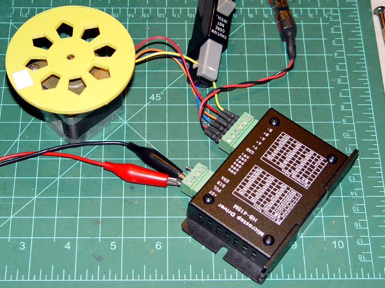
As mentioned there, the usual eBay vendor shipped HB-415M drivers instead of the advertised 2M415 drivers. Based on the Chinese datasheet and some poking around, I got a test setup working with a bench supply, a signal generator, and a NEMA 17 stepper motor with 2 Ω windings.
First observation: the ENA input is active high. Pulling it low to turn on the optocoupler disables the drive output, which is exactly the opposite of what’s shown in the datasheet, which means that the driver will run quite happily with nothing connected to the ENA pin. The optoisolator current runs about 11 mA from a 5 V supply, close enough to the 10 mA typical spec, but the signal generator thinks it’s providing a TTL pulse output.
Second observation: the driver’s actual winding current doesn’t match the DIP switch setting.
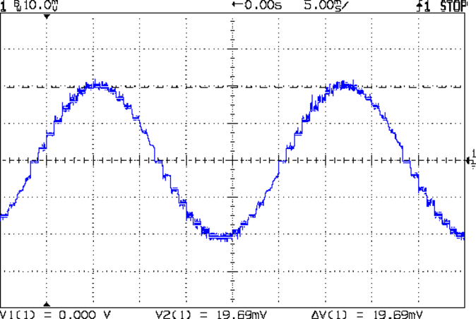
Here’s the 1/8 microstep winding current for the 1.50 A peak setting, with a 0.5 A/div vertical calibration:
HB-415M 8-step 1.5A 20V
Sure looks like 1 A peak, doesn’t it?
The ratio seems close to 0.707 and remains consistent across all current settings, so I’d lay long money that the designer confused “peak” and “RMS” values, then figured the current sense resistor or chose the internal coefficients to produce the corresponding RMS current for the peak value.
The reduced current produces not very much torque at all; negotiations are in progress for a partial refund based on eBay’s “item not as described” process…
Turns out that the anonymous parallel port breakout board isn’t compatible with an optoisolated stepper driver: each output has a 1 kΩ series resistor that limits the current well below the driver optocoupler’s expectations. The driver has an internal 300 Ω resistor on each input, too, which doesn’t help in this situation.
A detailed look at the resistors lined up in front of the connectors:
Anonymous parallel breakout board – series resistors
The breakout board would work fine with non-isolated drivers, like the Pololu breakout boards, so it’s not really at fault. The fact that there’s no doc anywhere to be found means you (well, I) couldn’t discover this without buying it first, but … I suppose it’ll come in handy for something.
One could short across the resistors, but I intended to use this board for the initial bringup and all that soldering defeats the purpose.
As nearly as I can tell, Epson designed a number of features into the R380 specifically to thwart CISS installation, including the awkward bridge across the middle of the printer that interferes with the flat tube feeding ink to the flying cartridges. I managed to route the previous CISS tubing around the bridge, but this time I figured enough was enough.
So I tucked a shop rag inside the printer, put a vacuum cleaner nozzle near the operation, and applied a fine-tooth pull saw to the bridge:
Epson R380 – bridge removed
That certainly simplified the rest of the installation…
Parallel port breakout boards of this ilk run about $14, complete with cable, on eBay:
5 axis parallel port breakout board
The PCB has no part number and the inferred URL isn’t productive. The “driver CD” accompanying it has doc for every possible board the vendor might sell and, absent a part number, the file names aren’t helpful. An exhaustive search suggests it corresponds to the HY-JK02-M 5-axis interface board manual.doc file.
Despite any implication to the contrary, the board does not have optoisolators between the parallel port pins and the outside world. The stepper driver bricks should, but the input signals from limit switches and suchlike connect directly to the guts of your PC.
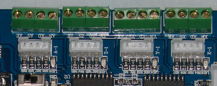
This overview (from the manual) shows the physical pin layout (clicky for more dots) and reveals the hidden silkscreen legend:
HY-JK02-M Breakout Board – overview
It looks like the board I got added a spindle relay driver transistor, plus a few resistors over by the manual control connector on the right.
Notice that the fourth terminal on each axis is GND, not the positive supply required for the optoisolators on the 2M415-oid driver bricks, which means you can’t just run a section of ribbon cable from the breakout board to the brick. You’ll need a separate +5 V (or whatever) power supply wire for each brick, with a common return to the system ground for this board. Those terminals are firmly bonded to the top and bottom ground planes on the board, so there’s no practical way to re-route them.
The small switch in the upper left, just to the right of the parallel port connector, selects +5 V power from the USB port (which has no data lines) or the power connector in the lower left. The LED near the switch won’t light up until you have both the parallel port cable and the USB cable plugged in.
The doc includes a timing diagram with no numeric values. I established that it can’t keep up with a 500 kHz pulse train and seems content at 100 kHz, but that’s conjecture. Setting the timing to match whatever the stepper driver bricks prefer will probably work. The diagram suggests the setup and hold times for direction changes are whatever you use for the minimum time between step pulses.
This shows the functional labels:
HY-JK02-M Breakout Board – function labels
The parallel port connector output pins, sorted by function:
Pin
9
1
2
14
16
3
7
8
6
5
4
17
Function
Spindle
motor
Enabled
X step
X dir
Y step
Y dir
Z step
Z dir
A step
A dir
B step
B dir
The parallel port connector input functions, sorted by pin:
X -Limit
Y- Limit
Z- Limit
A- Limit
Emerg Stop
10
11
12
13
15
The table uses Chinese for Pin 15: 急停.
It’s not clear whether the pins on the manual control connector are inputs or outputs, nor what the three separate Enabled lines do:
P1
P2
P3
P4
P5
P6
P7
P8
P9
P10
P11
P12
P13
P14
P15
B step
B dir
A dir
Z step
Y step
X step
X dir
Enabled
5V/VDD
5V/GND
A step
Z dir
Y dir
Enabled
Enabled
The three white connectors in the middle drive an LED readout board that’s probably most useful as a DRO for CNC-converted manual mills using the pendant for positioning.
The small white connectors duplicate the functions of the green screw terminals. They’re probably useful in a small machine that I’m not building.
This isn’t the board I intend to use in the final setup, because I need far more I/O pins, but it’ll serve for the short term.