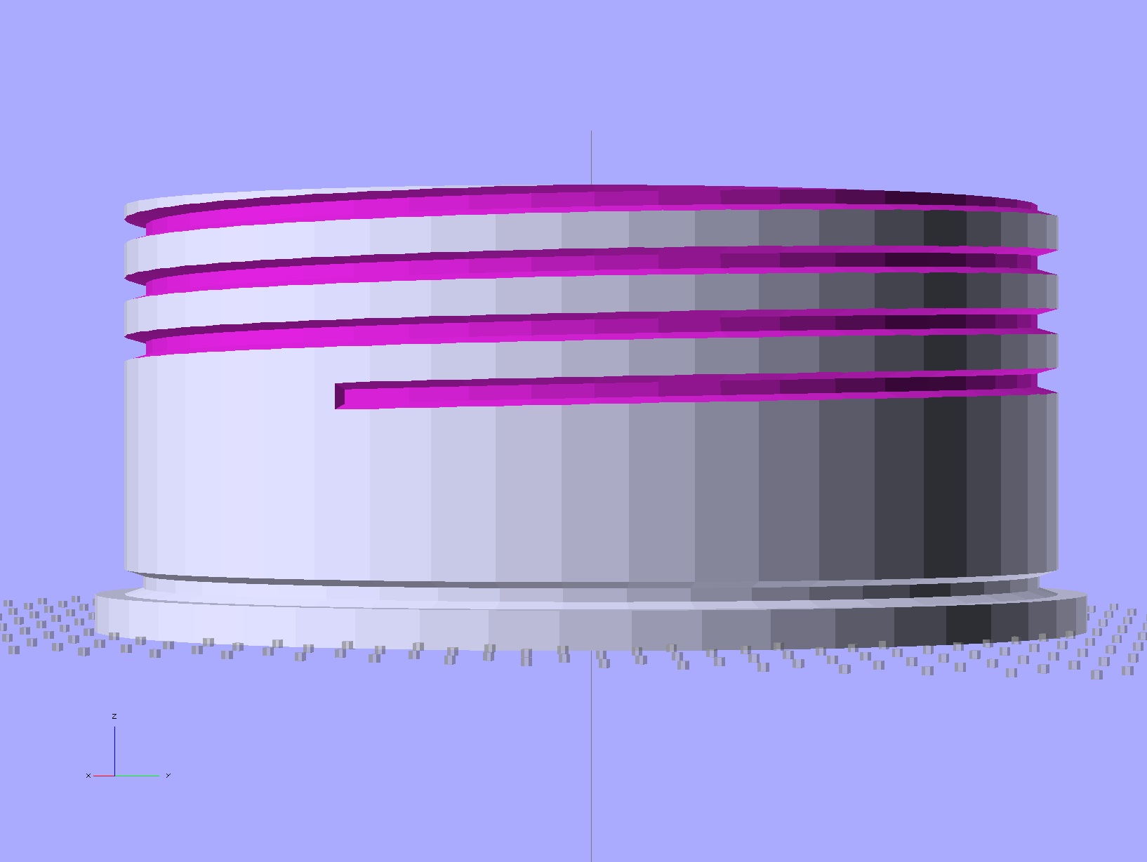
Although I don’t need another threaded plug, the most recent OpenSCAD version can handle a model including the thread dedendum:
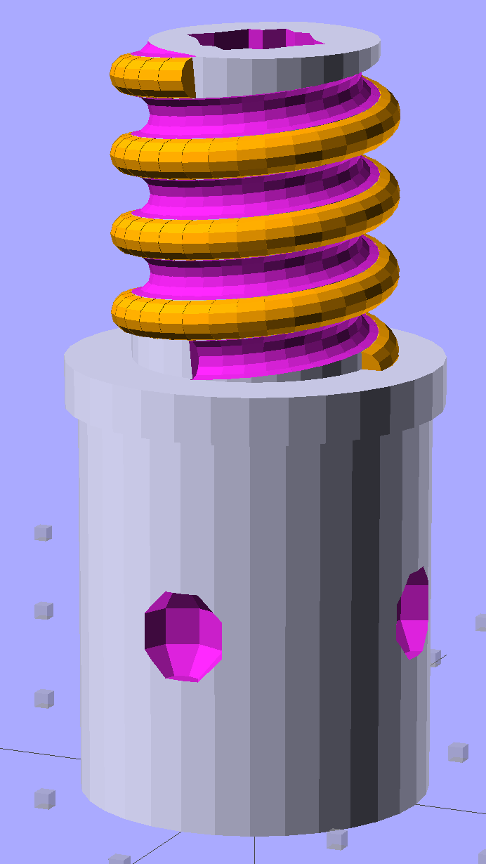
This hyper-close view (as always, clicky for more dots) shows the problem: the region where the addendum and dedendum meet at the pitch cylinder consists of a bazillion tiny faces:

The previous version simply couldn’t handle that many elements, but the new version has a parameter that I tweaked (to 100,000), allowing it to complete the rendering. Compiling to a solid model requires about 45 minutes, most of which probably involves those unprintably small facets.
The thread elements now taper slightly in the downhill direction, so that each quasi-cylinder nests cleanly inside the next to avoid the tiny slivers that stuck out of the joints in the previous model.
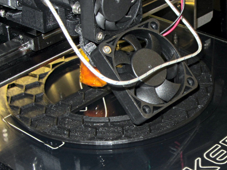
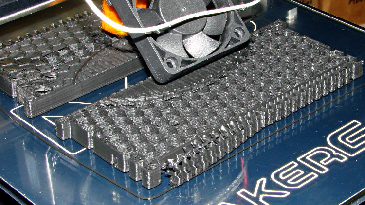
And the new Slic3r version (from GitHub) has better internal support for those indentations around the base, which means that AC vent plug might be build-able, too.
The OpenSCAD source code, with a few tweaks to nest the thread cylinders and properly locate the dedendum:
// Broom Handle Screw End Plug
// Ed Nisley KE4ZNU June 2013

//- Extrusion parameters must match reality!
//  Print with 2 shells and 3 solid layers

HoleWindage = 0.2;

Protrusion = 0.1;			// make holes end cleanly

//----------------------
// Dimensions

PostOD = 22.3;				// post inside metal handle
PostLength = 25.0;

FlangeOD = 24.0;			// stop flange
FlangeLength = 3.0;

PitchDia = 15.5;			// thread center diameter
ScrewLength = 20.0;

ThreadFormOD = 2.5;			// diameter of thread form
ThreadPitch = 5.0;

BoltOD = 7.0;				// clears 1/4-20 bolt
BoltSquare = 6.5;			// across flats
BoltHeadThick = 3.0;

RecessDia = 6.0;			// recesss to secure post in handle

OALength = PostLength + FlangeLength + ScrewLength;

$fn=8*4;					// default cylinder sides

echo("Pitch dia: ",PitchDia);
echo("Root dia: ",PitchDia - ThreadFormOD);
echo("Crest dia: ",PitchDia + ThreadFormOD);

Pi = 3.14159265358979;

//----------------------
// Useful routines

// Wrap cylindrical thread segments around larger plug cylinder

module CylinderThread(Pitch,Length,PitchDia,ThreadOD,PerTurn=32) {

CylFudge = 1.02;				// force overlap

    RotIncr = 1/PerTurn;
    PitchRad = PitchDia/2;

    Turns = Length/Pitch;
    NumCyls = Turns*PerTurn;

    ZStep = Pitch / PerTurn;

    HelixAngle = atan(Pitch/(Pi*PitchDia));
    CylLength = CylFudge * (Pi*(PitchDia + ThreadOD) / PerTurn) / cos(HelixAngle);

	for (i = [0:NumCyls-1]) {
		assign(Angle = 360*i/PerTurn)
			translate([PitchRad*cos(Angle),PitchRad*sin(Angle),i*ZStep])
				rotate([90+HelixAngle,0,Angle])
					cylinder(r1=ThreadOD/2,
							r2=ThreadOD/(2*CylFudge),
							h=CylLength,
							center=true,$fn=12);
	}
}

module PolyCyl(Dia,Height,ForceSides=0) {			// based on nophead's polyholes

  Sides = (ForceSides != 0) ? ForceSides : (ceil(Dia) + 2);

  FixDia = Dia / cos(180/Sides);

  cylinder(r=(FixDia + HoleWindage)/2,
           h=Height,
	   $fn=Sides);
}

module ShowPegGrid(Space = 10.0,Size = 1.0) {

  Range = floor(50 / Space);

	for (x=[-Range:Range])
	  for (y=[-Range:Range])
		translate([x*Space,y*Space,Size/2])
		  %cube(Size,center=true);

}

//-------------------
// Build it...

ShowPegGrid();

difference() {
    union() {
        cylinder(r=PostOD/2,h=PostLength);
        cylinder(r=PitchDia/2,h=OALength);
        translate([0,0,PostLength])
            cylinder(r=FlangeOD/2,h=FlangeLength);
        color("Orange")
        translate([0,0,(PostLength + FlangeLength)])
            CylinderThread(ThreadPitch,(ScrewLength - ThreadFormOD/2),PitchDia,ThreadFormOD);
    }

    translate([0,0,-Protrusion])
        PolyCyl(BoltOD,(OALength + 2*Protrusion),6);
    translate([0,0,(OALength - BoltHeadThick)])
        PolyCyl(BoltSquare,(BoltHeadThick + Protrusion),4);

    translate([0,0,(PostLength + FlangeLength + ThreadFormOD/2)])
		rotate(-90)
        CylinderThread(ThreadPitch,ScrewLength,PitchDia,ThreadFormOD);

	for (i = [0:90:270]) {
		rotate(i)
			translate([PostOD/2,0,PostLength/2])
				sphere(r=RecessDia/2,$fn=8);
	}
}