Ed Nisley's Blog: Shop notes, electronics, firmware, machinery, 3D printing, laser cuttery, and curiosities. Contents: 100% human thinking, 0% AI slop.
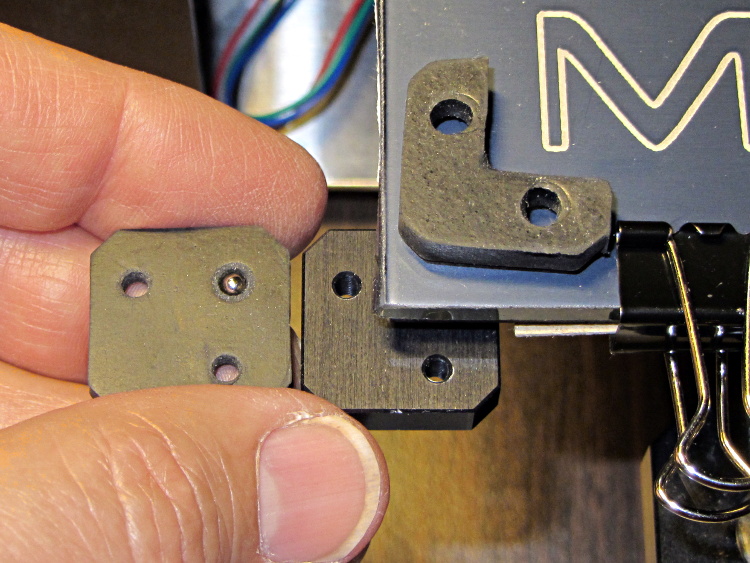
The pads measure just slightly less than 1/8 inch thick, so the balls support the aluminum heat spreader plate. Unlike the pads, the balls hold the plate at a constant distance from the spider which shouldn’t vary with mechanical load.
As nearly as I can tell, generic rubber expands by maybe 100 parts per million per degree C, so a 3 mm slab might expand by all of 0.02 mm over a 70 °C range: temperature obviously doesn’t make much difference. However, I’m about to add some hold-down clamps to keep the glass plate firmly in place and that pressure might squish the pads.
Obviously, putting a steel ball between two aluminum plates isn’t something you’d do in a high-stress machine, but the balls must support only the platform and won’t get any shock loading: any shock strong enough to indent the aluminum will probably shatter the glass. I’m pretty sure there won’t be enough motion in the XY plane to produce any wear, either.
Four points do not define a plane, but the spider and the spreader seem close enough to being planar that all four balls make firm contact. The M2 really does have a good mechanical foundation!
Somehow, I think I’m never going to get around to doing a CNC version of this thing, but at least now I have more pictures…
The overall problem comes from the fact that the Tour Easy frame geometry doesn’t match the expectations of the front shifter: the cable bends over a small finger that, on a diamond frame bike, should simply hold it in position. Here’s the finger, with a very early version of the pulley that just holds the cable slightly higher than the normal position, complete with one snapped wire showing that the pulley wasn’t getting the job done:
Front derailleur cable with broken strand
The obvious solution involves running the cable over a nice, rounded surface that prevents abrupt bending. The most recent version looks like this:
Shifter pulley installed – left view
Yes, the end of the cable sticks out over the chain; I haven’t tucked it in yet.
A bit of lathe work produces a 0.42 inch diameter thin brass disk with a 50 mil half-circle trench around it; in retrospect, the diameter of the trench bottom should be 0.42 inch and the OD should be about 0.45 inch. If you have really good parting-off-fu, you can produce a disk with a finished backside right on the lathe, but I had to drill an off-center hole anyway, so I thinned it on the Sherline:
Shifter pulley – thinning
It looks like this after all the thinning:
Shifter pulley – thinned
One flange is wider than the other: the thin flange faces front and gets a bunch of cutouts, the wide flange faces rearward and must support the bitter end of the cable.
I lined it up in the shifter, filed a notch to fit around the shifter finger, scribed the hole location, clamped it down, and drilled the hole:
Shifter pulley – center drilling
I think the hole could be on-center with the larger disk; now that I’m keeping better notes, I’ll try that next time. If so, then I can drill it on the lathe, part it off to the correct width, and hand-file the backside flat. The general idea is to have the cable pass over the finger, which almost happens with the smaller diameter.
Some tedious hand-filing produces notches that index over the finger and clear some protuberances on the shifter arm. This is the front face of the pulley that sits against the shifter arm, with a 5 mm socket head cap screw for scale:
Shifter pulley with bolt – front face
The rear face has one side of the trench filed away to get the cable out of the trench and around the bolt:
Shifter pulley with bolt – rear face
Then it looks like this from the right side of the bike:
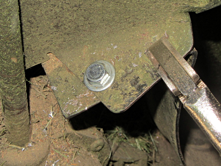
The lawn mower began emitting horrible crashes, which turned out to be coming from a flange at the rear of the mower housing that was formerly spot-welded to the main chassis. Those welds broke and the flange occasionally vibrated into contact with the blade, causing heartache and confusion for both parties.
Re-spot-welding the flange wasn’t in the cards, but the elaborately formed piece of steel did have a flat section in contact with another part of the chassis with just enough meat for a bolt. I grabbed the two with a Vise-grip, whacked the flange until it was more-or-less lined up where it should be, drilled a hole, and popped in a 1/4-20 bolt:
Mower flange – side view
The curved section of the flange faces the blade, with the vertical end pointed anti-spinward: the blade nicks that edge.
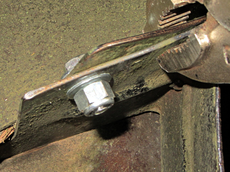
A dab of red Loctite and a nylock nut topped it off:
Adding a strip of white LEDs under the X stage helps shed some light on events atop the M2’s build platform; this was very nearly the first improvement after getting the printer, but somehow I’ve never written down where that nice white glow comes from.
This view shows the strip from below, looking up from the -Y direction in front of the stage:
White LED strip under X axis frame
I originally screwed the wires into the terminals from the hulking 12 V Dell laptop brick for the platform heater, but then I had to unscrew the wires whenever I moved the M2 and I didn’t like sharing the connectors with those huge conductors. Now the LEDs are in parallel with the extruder fan (which runs continuously), sharing the FAN1 screw terminals inside the electronics case.
The M2 firmware uses PWM to cut the 19.5 V supply from a much smaller laptop brick down to roughly 12 V RMS for the fans, but that isn’t such a Good Thing for LEDs. The strip has 120 Ω resistors that drop about 2.4 V at 20 mA from a 12 V supply, leaving 9.6 V for the LEDs (at about 3.2 V each). Running from 19.5 V means the resistors will see about 9.5 V and pass nearly 80 mA, four times the nominal rating, during each PWM pulse.
Based on those measurements, the light output doesn’t go up by nearly a factor of four during each pulse.
I plan to add a 12 V supply to the LinuxCNC box, probably by recycling the 12 V brick from the M2, which will get the LED current back down to a reasonable level. With any luck, they’ll survive this mistreatment and not carry a grudge.
You could, of course, just power the LEDs from a separate 12 V wall wart, but that adds Yet Another Thing when I carry the M2 to demos.
A simple test of additional insulation below the Makergear M2’s heated build platform, measuring the time required to heat the platform from 30 °C to 80 °C:
As-shipped without insulation: 8:20
Cardboard + cotton cloth: 8:30
Cardboard + aluminum foil + cotton: 8:00
That’s with a resolution of about 10 seconds and 1 °C. Ambient temperature was 25 °C; I preheated the platform to 30 °C for a repeatable starting point. The heater was full-on for the entire time and I tried to record the time until it first turned off at the setpoint temperature.
So my initial insulation didn’t make any difference; ten seconds (in the wrong direction!) seems down in the noise.
Adding aluminum improved the situation, but not by much.
The platform wasn’t moving, so there’s no air circulation on either surface. I think it will be possible to record / plot the platform heater duty cycle during printing using LinuxCNC’s HAL components, so some useful data should emerge from that.
I think the bottom line is that there’s so much heat transfer up through the glass plate and away that reducing the heat flow from the bottom by a little bit doesn’t matter…
Having recently kibitzed on a project using de-icing cables (with some success) to soften PVC pipe for bending, herewith the useful numbers.
Data printed on the original cable:
100 ft length
120 VAC
800 W
Derived values:
6.7 A = 800 W / 120 V
8 W/ft = 800 W / 100 ft
1.2 V/ft = 120 V / 100 ft
18 Ω = (120 V)2 / 800 W
180 mΩ/ft = 18 Ω / 100 ft
The starting point was a 62 ft length of the cable, as I’d long ago converted the end into a heated bed for starting plants early in the spring. That presented a resistance of 11 Ω, drew a current of 11 A, and dissipated 1.3 kW at 21 W/ft. A kilowatt-class dimmer handled the load, but adjoining sections of the cable got hot enough to melt the insulation and terminate the experiment.
A shorter length of cable might be suitable for a cheap laptop brick power supply. To keep the dissipation under, say, 10 W/ft, we have:
7.5 A = sqrt( 10 W/ft / 180 mΩ/ft )
1.3 V/ft = 7.5 A * 180 mΩ/ft
The Dell D220P-01 brick on the M2 provides 12 V at 18 A (!) and costs under $20 on eBay:
9 ft = 12 V / 1.3 V/ft
90 W = 12 V * 7.5 A
1.6 Ω = 9 ft * 180 mΩ/ft
You could run two 9 ft lengths cables in parallel from the same hulking brick. Whether that’s enough to soften a length of PVC pipe from the inside, without having the insulation get all melty, that’s another question…
I’m planning to put all the stepper driver bricks, solid state relays, power suppliers, miscellaneous doodads, and suchlike that will interface LinuxCNC with the M2 printer into a repurposed Dell desktop PC case.
The front of the case had some tabs sticking out that anchored / aligned / captured various bits of hardware; grabbing them with a Vise-Grip, wiggling until the steel failed, and then filing the raw edge solved that problem:
Dell PC case – removing small tabs
The PC had room for a diskette drive, with a lip protruding below the opening:
Dell PC case – diskette drive slot tab
A welding pliers wiggled nearly the entire tab at once:
PC case – removing diskette drive tab
The bulky Dell front panel had four locating pins that mated with four round holes, one of which appears in the first picture. I wanted a somewhat less butt-ugly front than the bare metal grill, but still with some air flow into the case, so I found some 1/4 inch diameter standoffs tapped 4-40 that fit snugly in the holes and cut them to length:
Dell PC case – trimming panel mounts
Another defunct Dell case contributed a side panel with roughly the right color. Four match-drilled clearance holes later:
Dell PC case – vent panel
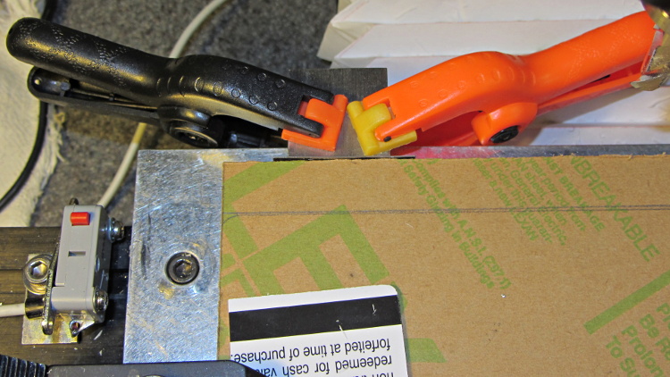
Just for effect, I squared up a slab of nice smoke-brown polycarb to cover the upper opening and perhaps hold das Blinkenlights. The slab was, as almost always happens, slightly too large for the Sherline, so I had to reclamp it to clean up all the sides. It came out about half a millimeter out of square and, being that type of guy, I clamped a block to the back of the table with a suitable spacer against the wide side, removed the spacer, loosened the step clamp on that end, rotated the slab against the block, made another pass, and it came out perfectly square:
Dell PC case – squaring polycarb panel
Four match-drilled holes and some epoxy later:
Dell PC case – polycarb panel mounts
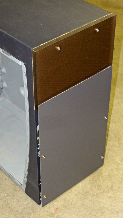
I’ll probably put the main AC switch on that top panel, but it looks pretty good even with the protective paper on the back:
Dell PC case – front panels
I must mill a recess under the vent panel and counterbore the screw heads so everything fits flush and lines up neatly.
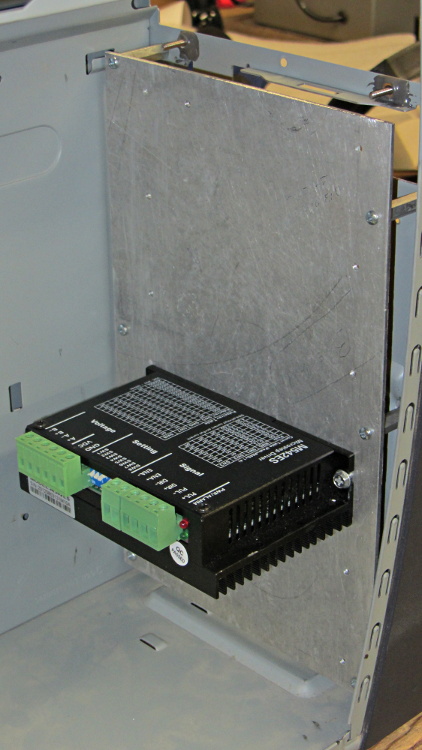
Another chunk of aluminum will hold the stepper driver bricks along the front of the case:
Dell PC case – stepper drive panel
I laid out the holes with a square, eyeballed the spacing on a machinist’s scale, manually punched / drilled / tapped the holes, and it’s all good. The standoffs provide a bit of airflow around the edges; I don’t expect the drivers to get more than slightly warm, because they’re running near the bottom of their current rating. Incidentally, that sheet is a different and much nicer alloy than the pure aluminum I jeweled for the main base plate and will probably not use.
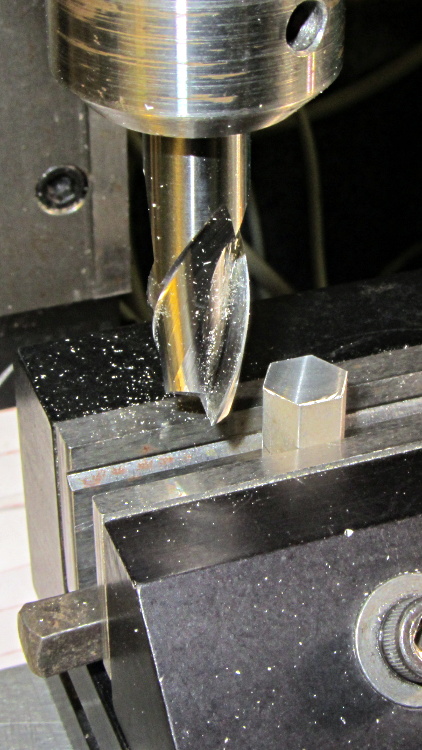
The 24 VDC power supply will mount on the top of the case, up where the Dell PC supply used to reside. The supply has M4 tapped holes and, of course, I don’t have any such standoffs, but I did find some hex standoffs with 6-32 tapped holes on both ends. Bandsaw ’em in half and clean up the raw end to the proper length:
Dell PC case – power supply standoffs – trimming
Center drill in the lathe / drill / tap an M4 thread in each one, saw off some M4 screws, slather with red Loctite, insert studs into standoffs, and that should hold the power supply in place with 6-32 screws through the case top:
Dell PC case – power supply standoffs
More Quality Shop Time lies ahead, but it’s coming together…