Ed Nisley's Blog: Shop notes, electronics, firmware, machinery, 3D printing, laser cuttery, and curiosities. Contents: 100% human thinking, 0% AI slop.
I picked a 3.0 pixel/mm scale factor, so a 33 mm mold covers only 100 pixels. That image is 1100 mm tall and will be reduced by a factor of 10 to the final image size: this is not the place for fine detail and fancy lettering!
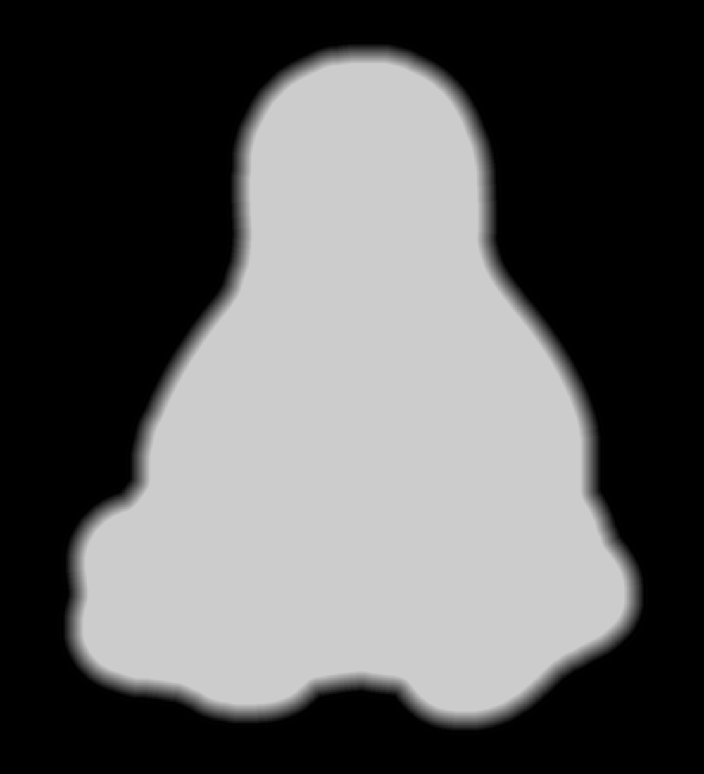
The conversion process assumes you’ll handle the Z axis scaling yourself, so the script no longer normalizes the gray levels. If you select gray levels using HSV, the V slider gives you a direct reading in percent-of-maximum thickness; Tux varies from V = 80 to 100, so he’s pretty much bas relief.
The border around the image must be 0 = black and will be stripped from the final mold. That’s why Tux doesn’t turn into a bird served on a rectangular platter.
Because this is a mold, its edges must have some draft, which means the outline must shade from black to whatever gray represents the interior of the mold. Do this:
Trace the outline using the Scissors Select tool = snap to high-contrast outer edge
Create / go to a new layer filled with whatever gray you want for the interior (V = 80 here)
Select → Grow the selection by 60 pixels (on a 1000×1100 image)
Select → Invert to select the exterior of the outline
Bucket fill the exterior with 0 = black
Select → Invert to select the interior of the outline again
Select → Border: Add a 30 pixel border to the selection with the “Feather border” option
Bucket fill the border with 0 = black
Unselect and you have a layer with a nice graduation around the mold
Which looks like this with V=80 gray inside:
Tux Mold – Height Map – outline gradient
The 30 pixel feathered border, scaled by the 10× reduction, means the edge of the mold goes from 0 = black to the interior in about 3 pixel / (3 pixel/mm) = 1 mm. If the interior is 255 = white at 7 mm, the draft angle is arctan 1/7 = 8°, which is probably about right for the deepest part of the mold. The edge of the Tux mold is V = 80 (or about 200 gray), so it’s at 0.8 × 7 mm = 5.6 mm and the draft angle is arctan 1/5.6 = 10°.
Inside the mold, anything goes, but you should avoid 0 = black levels so that the alignment pins don’t poke through the mold. Any 255 = 100 V = white levels will be the maximum mold thickness, which is 7 mm for the molds you see here and that may be somewhat too thick for a chocolate treat. It is really hard to maintain draft on small features, but I think if you don’t get carried away it’ll be all good.
There’s also a 1 mm backing plate below the mold that ensures the deepest mold parts have some substance behind them and the alignment pin sockets have enough depth to be useful.
Scaling the image down by 10× to about 110 pixels tall (including the black border) will make the final Tux mold about 37 mm tall:
Tux
This image enlarges it by 10× with no smoothing to show the gritty nature of the image. This is why you can’t have delicate detail or fine lettering:
Tux – enlarged to show texture
Notice the nearly complete lack of draft on the interior features. Each level differs by about V = 5 over the range V = 80(the border) to V = 100 (beak and flipper), so they amount to only 0.05 × 7 mm = 0.35 mm = one or two thread layers at 0.20 mm/layer. I think if you were doing this right, you’d pick an overall thickness so that V = 5 increments corresponded to one layer or use whatever V increments corresponded to a single layer.
Running that image through the Bash script & OpenSCAD programs (more on those later) produces a reasonable result:
Tux positive mold – solid model – oblique
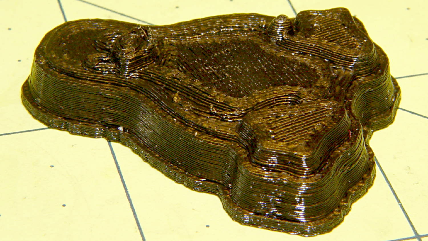
When it’s converted into plastic, you can count the layers in each V = 5 level (clicky for more dots):
Tux positive mold – plastic – oblique
It may be a bit less rounded in the tummy than the real Tux, but seems good enough for the purpose.
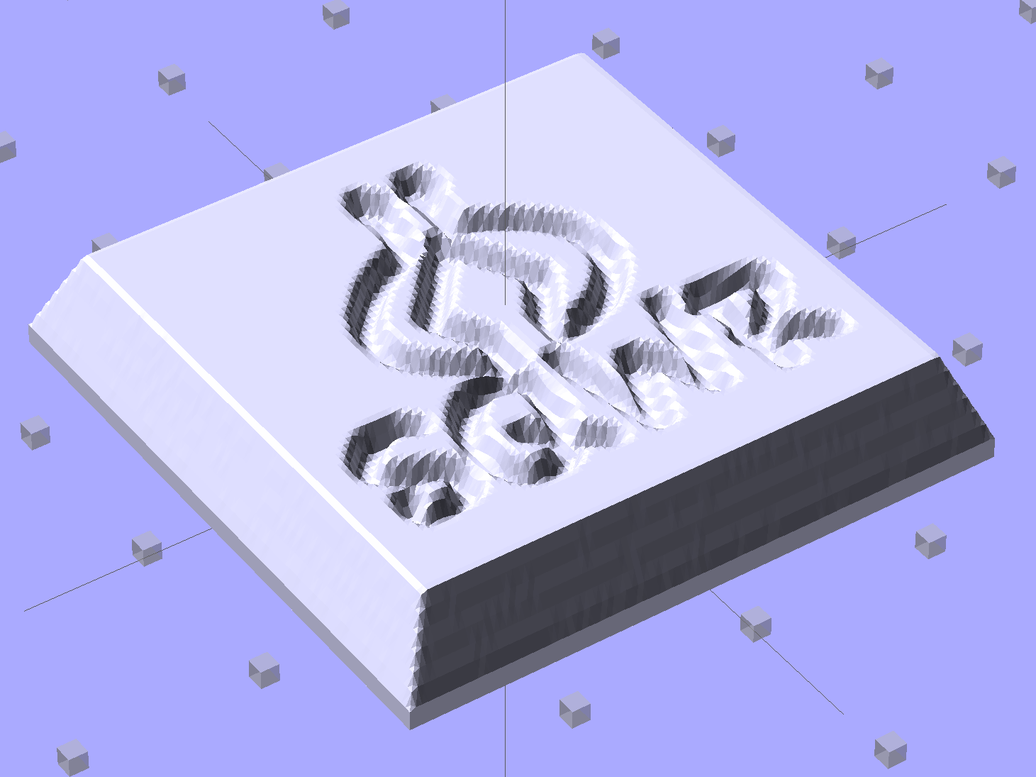
Given an STL file generated from a height map image, import it into OpenSCAD:
SqWr solid model – OpenSCAD – oblique view
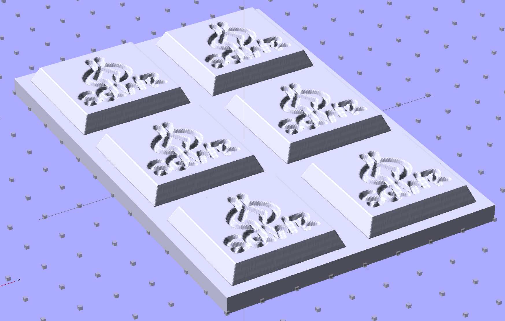
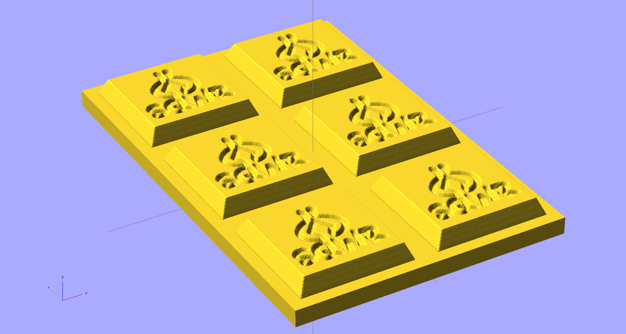
Then slide a plate under six copies to produce a positive model for a casting mold:
SqWr Positive Mold Framework – 2×3
This is one of the few cases where the compiled-and-rendered version looks better, as though you’d shrink-wrapped it in gold foil:
SqWr Positive Mold Framework – 2×3 – gold
The height map STLs each have a bazillion tiny facets that take forever-and-a-day (well, the better part of half an hour for this set) to render, not to mention that the whole array would take two hours to print… and then be used once or twice to produce the flexy silicone negative mold.
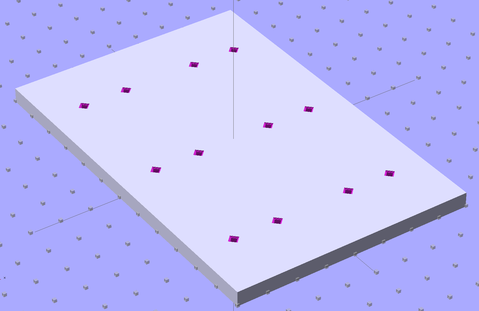
So it’s better to have a generic frame with alignment pin holes that you print once:
SqWr Positive Mold Framework – 2×3 pins
Better yet, just CNC-drill those holes in a nice, flat acrylic / polycarbonate slab.
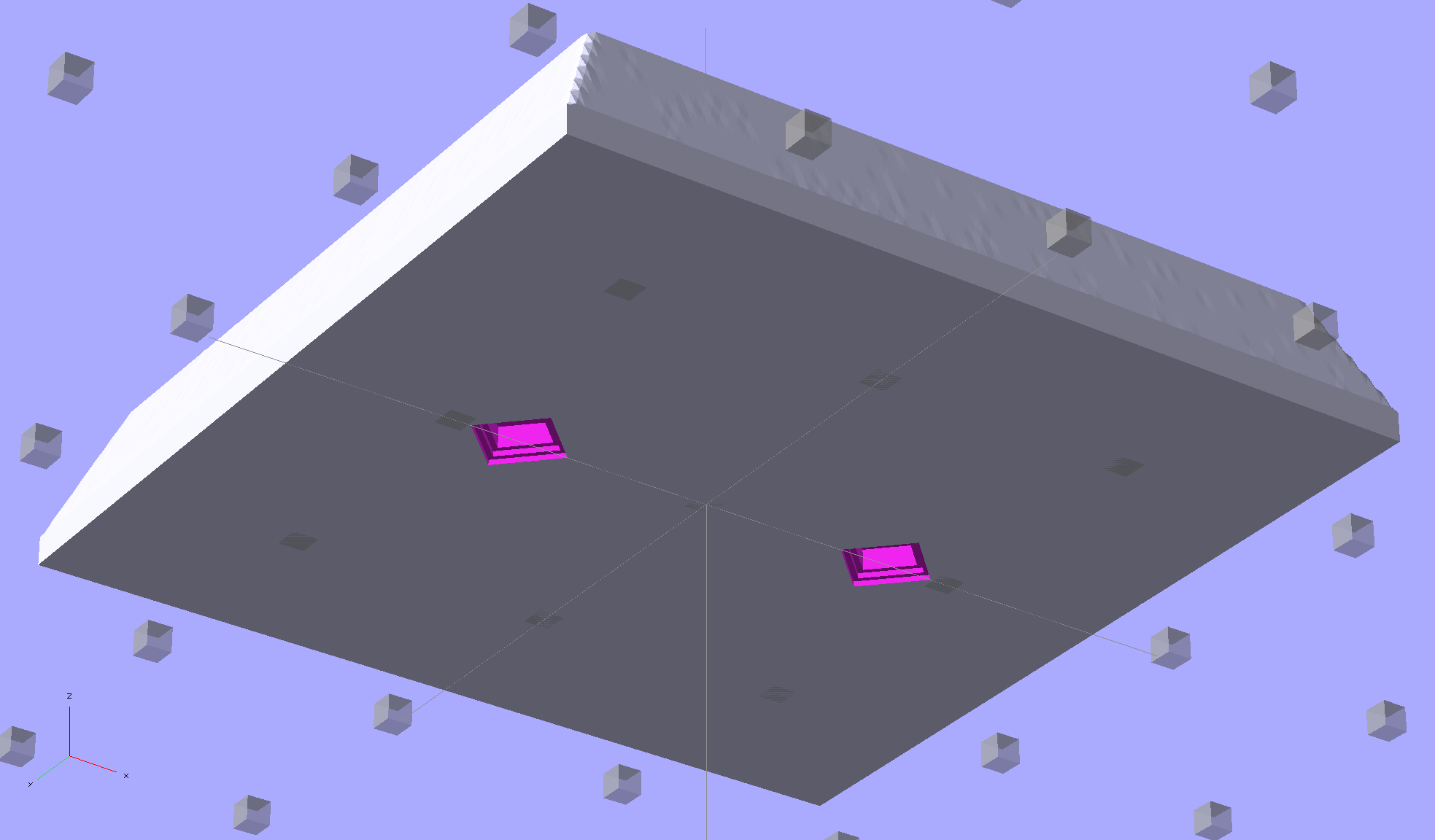
The OpenSCAD program can punch matching holes in the back of the small mold:
SqWr solid model – OpenSCAD – oblique bottom
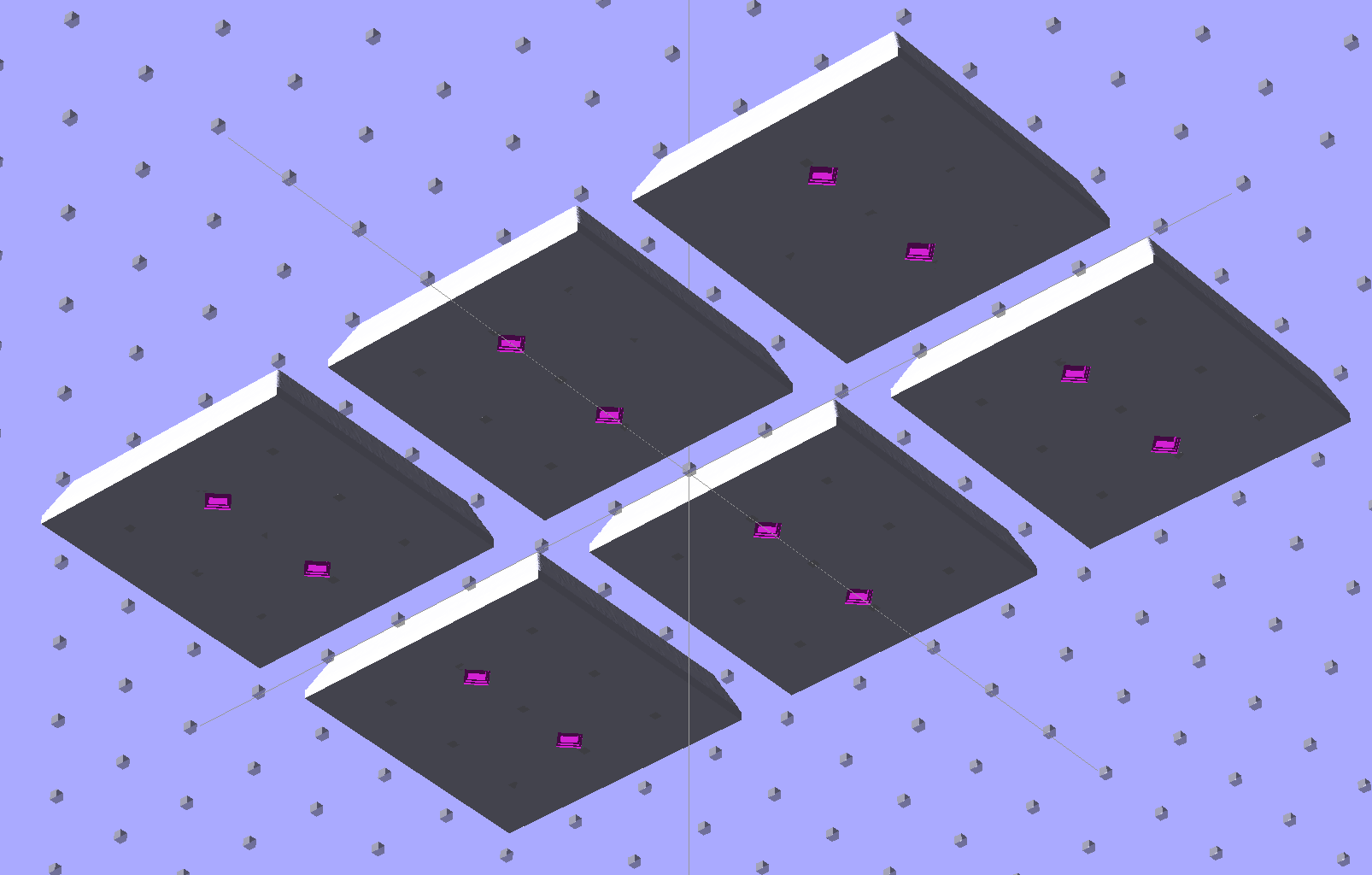
Or you could print out an array of the things with holes:
SqWr solid model – 2×3 array – bottom
It’s not clear having OpenSCAD labor for half an hour to generate and emit a single STL file spanning all six molds is a win. Given that you don’t care about the mold-to-mold spacing, having Slic3r duplicate the same small STL file half a dozen (or more!) times would probably be a net win.
There’s no reason the OpenSCAD program that creates the original STL from the height map image can’t punch alignment pin holes, too, which would avoid this import-and-recompile step. If you’re going with a CNC-drilled plate, then it would make even more sense to not have a pair of OpenSCAD programs.
Anyhow.
Apply a handful of small molds to the backing plate with tapeless sticky, butter it up with mold release agent, slather on silicone putty, flip it over to produce a smooth surface “under” the small molds (so you can rest it flat on a table when pouring molten chocolate into the cavities), cure, peel, and you’d get a pretty good negative mold.
This may not make any practical sense, but it was easy & fun to see what’s possible…
The OpenSCAD source code:
// Positive mold framework for chocolate slabs
// Ed Nisley - KE4ZNU - January 2014

Layout = "FramePins";		// Molds FramePins FrameMolds Frame Single Pin

//- Extrusion parameters must match reality!
//  Print with 2 shells and 3 solid layers

ThreadThick = 0.20;
ThreadWidth = 0.40;

Protrusion = 0.1;			// make holes end cleanly

HoleWindage = 0.2;

//----------------------
// Dimensions

FileName = "SqWr-press.stl";	// overrride with -D

Molds = [2,3];					// count of molds within framework

MoldOC = [40.0,40.0];			// on-center spacing of molds
MoldSlab = 1.0;					// thickness of slab under molds

BaseThick = 5.0;

BaseSize = [(Molds[0]*MoldOC[0] + 0),(Molds[1]*MoldOC[1] + 0),BaseThick];
echo(str("Overall base: ",BaseSize));

PinOD = 1.75;					// locating pin diameter
PinLength = 2.0;				//  ... total length
PinSpace = 15.0;				// spacing within mold item

//----------------------
// Useful routines

//- Put peg grid on build surface

module ShowPegGrid(Space = 10.0,Size = 1.0) {

	RangeX = floor(100 / Space);
	RangeY = floor(125 / Space);

	for (x=[-RangeX:RangeX])
		for (y=[-RangeY:RangeY])
			translate([x*Space,y*Space,Size/2])
			%cube(Size,center=true);

}

module PolyCyl(Dia,Height,ForceSides=0) {			// based on nophead's polyholes

  Sides = (ForceSides != 0) ? ForceSides : (ceil(Dia) + 2);

  FixDia = Dia / cos(180/Sides);

  cylinder(r=(FixDia + HoleWindage)/2,
           h=Height,
	   $fn=Sides);
}

// Locating pin hole with glue recess
//  Default length is two pin diameters on each side of the split

module LocatingPin(Dia=PinOD,Len=0.0) {

	PinLen = (Len != 0.0) ? Len : (4*Dia);

	translate([0,0,-ThreadThick])
		PolyCyl((Dia + 2*ThreadWidth),2*ThreadThick,4);

	translate([0,0,-2*ThreadThick])
		PolyCyl((Dia + 1*ThreadWidth),4*ThreadThick,4);

	translate([0,0,-(Len/2 + ThreadThick)])
		PolyCyl(Dia,(Len + 2*ThreadThick),4);

}

module LocatingPins(Length) {
	for (i=[-1,1])
	translate([i*PinSpace/2,0,0])
		LocatingPin(Len=Length);
}

//-- import a single mold item

module MoldItem() {
	import(FileName,convexity=10);
}

//-- Overall frame shape

module Frame() {

	translate([0,0,BaseSize[2]/2])		// platform under molds
		cube(BaseSize,center=true);

}

//- Build it

ShowPegGrid();

if (Layout == "Pin")
	LocatingPin(Len=PinLength);

if (Layout == "Single")
	difference() {
		MoldItem();
		LocatingPins(PinLength);
	}

if (Layout == "Frame")
	Frame();

if (Layout == "Molds") {
	translate([-MoldOC[0]*(Molds[0] - 1)/2,-MoldOC[1]*(Molds[1] - 1)/2,0])
	for (i=[0:Molds[0]-1],j=[0:Molds[1]-1])
		translate([i*MoldOC[0],j*MoldOC[1],0])
			difference() {
				MoldItem();
				LocatingPins(PinLength);
			}
}

if (Layout == "FramePins")
	difference() {
		Frame();

		translate([-MoldOC[0]*(Molds[0] - 1)/2,-MoldOC[1]*(Molds[1] - 1)/2,0])
			for (i=[0:Molds[0]-1],j=[0:Molds[1]-1])
				translate([i*MoldOC[0],j*MoldOC[1],BaseSize[2]])
					LocatingPins(BaseThick);
	}

if (Layout == "FrameMolds") {
	Frame();
	translate([-MoldOC[0]*(Molds[0] - 1)/2,-MoldOC[1]*(Molds[1] - 1)/2,0])
		for (i=[0:Molds[0]-1],j=[0:Molds[1]-1])
			translate([i*MoldOC[0],j*MoldOC[1],BaseThick - MoldSlab + Protrusion])
			MoldItem();
}
Given that you really don’t care about the absolute dimensions, you can generate a positive mold from a height map image and avoid the entire solid modeling process. Having already solved the cookie press problem, this was a quick-and-easy feasibility study…
Start by selecting the logo, growing the selection by a few pixels, and feathering the edges to produce the mold draft. Then apply a square gradient behind the Squidwrench logo to produce the height map for the edge of the mold. This one is scaled at 3.0 pixel/mm and is 100×100 pixel, thus producing a 33 mm square mold:
One could, of course, produce a non-square mold with a different gradient outline shape.
Hand the image to a slightly modified version of the cookie press script (see below) to get an STL file of the mold:
SqWr solid model – oblique view
Feed the STL into Slic3r, hand the G-Code to Pronterface, fire the M2!, and you get a positive mold that looks enough like black chocolate to seem ready-to-eat:
SqWr – mold positive
I have no idea whether that will work as a mold, but I suspect flexy silicone putty won’t reproduce much of the fine plastic filament detail, so the negative mold won’t grab the chocolate. The logo is six threads deep with a little bit of draft, if that makes any difference.
The backing plate is 1 mm thick and the height map is 5 mm stacked atop that. A few iterations suggested using about 0.75 gray for the logo; working backwards says 5 mm = 25 layers @ 0.20 mm/layer, so a depth of 0.25 * 25 is about six threads.
For production use, I’d be tempted to import maybe a dozen copies of the STL into OpenSCAD, mount them on a platform with a gutter and a lip on the outside, and then print the whole positive multi-cavity mold in one shot.
The Bash script that produces the mold strongly resembles my cookie cutter script and contains about as much cruft as you’d expect. Because we need a positive mold, not a negative press, the script doesn’t invert the colors or flop the image left-to-right, nor does it generate the cookie cutter STL around the outside of the press:
The price for this specialized wrench used to extract oxygen sensors took a big jump some time after I added a link to it:
Northern Tool Sensor Socket – Absurd Lowest Price
Were it not for the very specific part number that’s certainly not available anywhere else, you could take advantage of their “Guaranteed Lowest Prices” to make a quick $494.
The fancy OXO can opener doesn’t work well on #10 cans, so we bought a not-bottom-dollar can opener with comfy handles to replace the one that convinced us to get the OXO. After maybe a year, tops, it gradually stopped working well, too, which prompted a trip to the Basement Shop Workbench.
The symptoms:
The handle wouldn’t move the cutter during maybe 1/4 of its revolution
It pushed the handles apart during another quarter turn
Look carefully and you’ll see the teeth sticking out slightly more on the right side of the drive wheel:
Can opener – drive gear misalignment
When those protruding teeth line up with the gear behind the cutter wheel, the handles open and the drive wheel loses its grip. When the low side lines up with the cutter gear, the gears very nearly disengage.
Taking it apart shows that both “gears” (which is using the term loosely) have been pretty well chewed up:
Can opener – gears and cutters
Destroying those gears should require a lot more strength than either of us can deploy on a regular basis, which suggests they used mighty soft steel. It’s not obvious, but the drive gear hole is just slightly larger than the screw thread OD; it doesn’t ride on an unthreaded part of the screw shaft.
I’m not in the mood for gear cutting right now, so I filed down the wrecked teeth and buttoned them up with some attention to centering the gear. The can opener works, but sheesh this is getting tedious…
The Sony HDR-AS30V “action camera” uses NP-BX1 lithium batteries (3.7 V @ 1.24 A·h = 4.6 W·h) that are, of course, a completely different size and shape than any other lithium battery on the planet.
So.
Tweaking a few dimensions in the Canon NB-6L source code, tinkering with the layout of the contact pins, and shazam Yet Another 3D Printed Battery Test Fixture:
NP-BX1 Holder – show layout
It builds nicely, although the contact pin tunnels are a bit too close to the top of the case:
Sony NP-BX1 Holder – on platform
After reaming out the contact pin holes to the proper diameters & depths, then gluing the plugs in place, it works just as you’d expect:
Sony NP-BX1 battery holder
It’s worth noting that the Wasabi charger accepts the batteries upside-down, with the conspicuous chevron against the charger body. It’s definitely not the way all the other chargers work. The keying recesses on the battery (corresponding to the blocks in the solid model) lie along the bottom edge of the contact surface, so flipping the battery over means they’ll hold it in place, but … oh, well.
That grotty Powerpole connector last saw use in some random benchtop lashup. At some point I’ll be forced to start making more of those.
These quilting pin caps are slightly longer than the previous version and, due to the M2’s smaller nozzle, have slightly thinner single-thread walls. Because Slic3r does a better (although not ideal) job of path planning than Skeinforge, it’s easier to create an array of the caps in the solid model than to manually add duplicates in Slic3r:
Fill with silicone caulk on waxed paper and they look even more like that:
Quilting pin caps – silicone fill
Fast-forward a few days, rub off the excess caulk, trim off a few blobs, and they’re ready for presentation:
Quilting pin caps – finished
In use, they look about like you’d expect:
Quilting pin caps – in use
The pin caps I made from a 5 gallon bucket’s O-ring gasket didn’t work out well, as the plastic didn’t like being poked with pins and put up a stiff resistance. Silicone caulk has exactly the right consistency.
When Mary ramps up a full-scale quilt, we’ll need a few hundred of the things. The commercial version has dropped to 40 cents each, which makes all this worthwhile.
The OpenSCAD source code:
// Quilting pin caps
// Ed Nisley KE4ZNU April 2012
//	January 2013 - modify for Slic3r and M2

//- Extrusion parameters must match reality!
//  Print with +1 shells and 3 solid layers

ThreadThick = 0.20;
ThreadWidth = 0.40;

HoleWindage = 0.2;

function IntegerMultiple(Size,Unit) = Unit * ceil(Size / Unit);

Protrusion = 0.1;			// make holes end cleanly

//----------------------
// Dimensions

ID = 5.0;
OD = ID + 2*ThreadWidth;
Length = 8.0;
Sides = 8;

CapArray = [6,6];			// XY layout of caps
CapsOC = OD + 2.0;			// OC spacing

//----------------------
// Useful routines

module PolyCyl(Dia,Height,ForceSides=0) {			// based on nophead's polyholes

  Sides = (ForceSides != 0) ? ForceSides : (ceil(Dia) + 2);

  FixDia = Dia / cos(180/Sides);

  cylinder(r=(FixDia + HoleWindage)/2,
           h=Height,
	   $fn=Sides);
}

module ShowPegGrid(Space = 10.0,Size = 1.0) {

  RangeX = floor(100 / Space);
  RangeY = floor(125 / Space);

	for (x=[-RangeX:RangeX])
	  for (y=[-RangeY:RangeY])
		translate([x*Space,y*Space,Size/2])
		  %cube(Size,center=true);

}

module PinCap() {
	rotate(180/Sides) {
		difference() {
		PolyCyl(OD,Length,8);
		translate([0,0,-Protrusion])
			PolyCyl(ID,(Length + 2*Protrusion),8);
		}
	}

}

//----------------------
// Build them!

ShowPegGrid();

translate([(-CapsOC*(CapArray[0] - 1)/2),(-CapsOC*(CapArray[1] - 1)/2),0])
	for (i=[0:(CapArray[0] - 1)],j=[0:(CapArray[1] - 1)])
		translate([i*CapsOC,j*CapsOC,0])
			PinCap();