The Smell of Molten Projects in the Morning

Ed Nisley's Blog: Shop notes, electronics, firmware, machinery, 3D printing, laser cuttery, and curiosities. Contents: 100% human thinking, 0% AI slop.

Category: Machine Shop

Mechanical widgetry

  • Image File Recovery Redux

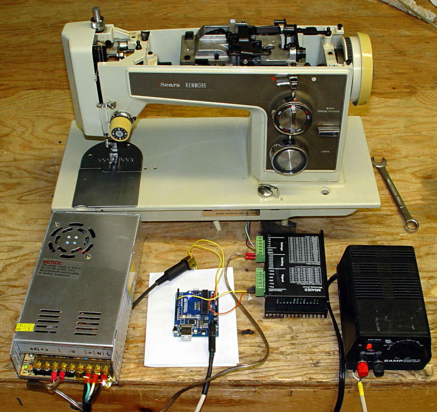
    Took a picture of the sewing machine setup with the Sony DSC-F717, transferred it into DigiKam, got the “done transferring, you can disconnect the camera” message, believed it, disconnected the camera, deleted the image file, and then discovered that DigiKam mislaid the image file.

    Rather than re-set-up and re-take the shot, I followed my own directions and recovered the image from the Memory Stick:

    dmesg | tail
    [43176.079853] usb 2-1.6.3: New USB device strings: Mfr=1, Product=2, SerialNumber=0
    [43176.079855] usb 2-1.6.3: Product: Sony PTP
    [43176.079856] usb 2-1.6.3: Manufacturer: Sony
    [43198.073652] usb 2-1.6.3: USB disconnect, device number 22
    [43333.788533] sd 9:0:0:0: [sdc] 1947648 512-byte logical blocks: (997 MB/951 MiB)
    [43333.803292] sd 9:0:0:0: [sdc] No Caching mode page found
    [43333.803299] sd 9:0:0:0: [sdc] Assuming drive cache: write through
    [43333.824681] sd 9:0:0:0: [sdc] No Caching mode page found
    [43333.824688] sd 9:0:0:0: [sdc] Assuming drive cache: write through
    [43333.825491]  sdc: sdc1
    sudo dd if=/dev/sdc of=/tmp/pix.bin bs=1M
    ^C615+0 records in
    614+0 records out
    643825664 bytes (644 MB) copied, 38.5841 s, 16.7 MB/s
    strings -t x pix.bin | grep Exif | head
      68006 Exif
     208006 Exif
     3f8005 _Exif
     7b8006 Exif
    13d8006 Exif
    15b0005 wExif
    1798005 CExif
    19c0006 Exif
    1b90006 Exif
    1f98005 %Exif
    dd if=pix.bin of=image03.jpg bs=$((16#1000)) count=1K skip=$((16#3f8))
    1024+0 records in
    1024+0 records out
    4194304 bytes (4.2 MB) copied, 0.0121431 s, 345 MB/s
    display image03.jpg
    convert image03.jpg dsc00656.jpg
    

    Obviously, there was a bit more flailing around than you see here, but that’s the gist of the adventure. For what it’s worth, image01 was a random blurred shot and image02 is the ID picture I keep on all my cameras.

    The convert step discards all the junk after the end of the image, so the dsc00656.jpg file doesn’t include anything unexpected.

    The picture isn’t all that much to look at, even after cropping out the background, but …

    Kenmore 158 - stepper drive test
    Kenmore 158 – stepper drive test

    The advantage of the manual method: renewing one’s acquaintance with tools that come in handy for other tasks.

  • Makergear M2 Filament Drive Motor: Status Check

    A friend had his Makergear M2 filament drive motor stop driving the filament; the problem turned out to be a severely worn pinion gear on the motor shaft. Perhaps Makergear got a pallet of bad motors, as the problem seems to affect a batch of printers made during the middle of 2013, more or less.

    The motor on my printer came off the line in early 2013, if that’s really a date code:

    M2 Extruder motor - data sticker
    M2 Extruder motor – data sticker

    There’s no manufacturer, but the 104022 number matches up with a Kysan motor. The description doesn’t say anything about the interior of the gearbox, but that’s not surprising. The gear ratio is 5.2:1, not the 5:1 I’d been assuming, which gets compensated out later on.

    The pinion gear is worn, but not severely, and the three planet gears are in fine shape:

    M2 Extruder - planetary gears
    M2 Extruder – planetary gears

    Slather everything with lithium gear grease, stuff the parts back in place, and it’s all good.

    The socket-head set screws may have a bit of threadlock, as they’re firmly set in place, and, as you’d expect, Harbor Freight hex wrenches are made of butter-soft steel that’s totally useless in sizes below about 2.5 mm. In fact, those screws rounded the end of an old Craftsman wrench, so maybe they’re slightly oversize.

  • Forester Trailer Hitch: Wiring Installation

    Unlike the trailer hitch installation instructions, the wiring installation instructions left a bit to be desired. Basically, you can’t get the trim panels off the interior until you know where they hid the snaps and latches, but you can’t find the snaps and latches before you remove the trim panels.

    N.B.: this applies to a 2015 Forester. Subaru deliberately moves the connector around for each model and year, for reasons that certainly make sense to them.

    Remove everything from the back end of the car that isn’t firmly affixed.

    Remove the rivets from the left-side foam block by prying their heads with a big screwdriver; maybe you can get a needlenose pliers under there. They’re surprisingly difficult to get out, due to that nasty barb on the end:

    Forester cargo compartment foam block rivet and socket
    Forester cargo compartment foam block rivet and socket

    Release the left side of the trim strip across the back of the compartment by pulling the front corner forward to unlock the latch that engages the trim panel on the left edge. Then you can pull the strip upward to locate the green rivet about a foot from the left end, stick a screwdriver under there, and pry it out of the frame. I didn’t do that, with the unhappy result that the rivet stayed in the frame:

    Forester hatch trim - snap rivet location
    Forester hatch trim – snap rivet location

    If that happens to you, just pry the rivet out of the frame, slide it into the trim strip, and (when the time comes), ram it back into the frame.

    A captive plastic cover over the bolt securing the cargo tiedowns yields to a fingernail, if you know that’s what you must do:

    Forester cargo tiedown - screw location
    Forester cargo tiedown – screw location

    Remove the bolt and tiedown, which greatly simplifies pulling the side trim panel away from the frame:

    Forester trailer wiring connector location
    Forester trailer wiring connector location

    The trailer hitch connector lies tucked far up inside the recess, taped to the wiring harness with blue tape. Slit the tape, pull the connector free, worm the aftermarket wires up in there, latch the connectors together, and reinstall everything in reverse order.

    Subaru could, if they wanted to, add a foot of wire to that harness, tape it near the bottom edge of the trim panel, and eliminate half an hour of dealer labor charge. I think I understand why they don’t do that, but I don’t have to like it.

    It’s faintly possible that someone with very thin arms could reach the connector without dismantling the butt end of the car, but the fingers on the end of that arm might not have enough strength to latch the connectors.

    The electrical box fit neatly against the rear of the compartment, behind the foam block. A bit of razor knife artistry carved a notch for the fuseholder and the wiring coils up neatly inside an existing recess:

    Forest trailer hitch - wiring in cargo compartment
    Forest trailer hitch – wiring in cargo compartment

    Until I install lighted hitch nuts (you could look it up), I think deploying the trailer connector through the hatch makes more sense than running the wiring through one of the holes in the spare tire well and exposing the connector to the elements. I don’t intend to do much trailer hauling …

  • Interplak Water Jet: End of the Line

    The brittle tubing on Mary’s Interplak water jet continued to disintegrate, so I replaced the entire tube with Tygon:

    Interplak water jet - interior
    Interplak water jet – interior

    Nisley’s First Rule of Plumbing: Never, ever look inside the pipes delivering water to your faucet.

    Interplak handle - interior view
    Interplak handle – interior view

    That’s not quite inside the pipes, but it’s pretty grotendous, isn’t it?

    As expected, flexible tubing doesn’t transmit the pressure pulses nearly as well as the OEM rigid tubing, so we finally bought a new Waterpik. At least you can get replacement tubing for Waterpiks, but I’ll wait until it fails before stocking up.

    Contrary to what you might expect, I cut the Interplak’s cord, harvested the motor windings, and dumped the carcass in the trash.

  • Forester Trailer Hitch: Installation Notes

    Start with loose parts rattling around inside a battered cardboard package:

    Trailer hitch receiver - as received
    Trailer hitch receiver – as received

    I backed the Forester up to put the rear tires over the edge of the garage apron, which provided enough room to work underneath without jacking the thing; there’s a chock under the left front wheel, never fear.

    The instructions from etrailer.com were entirely adequate, so there’s not much point in a detailed writeup. Their time estimate (an hour) seems grossly understated, but I wasn’t in any hurry.

    A morning of pleasant wrenching produced a good-looking, albeit nearly invisible, result:

    Forester trailer hitch - installed
    Forester trailer hitch – installed

    Both hitches bolt directly to the frame and I have no idea what effect that has on the collision behavior. My guess is that the Subaru hitch would be more bendy, if only because it has a much lower load rating, but that probably doesn’t make much difference.

    Some notes:

    Remove the muffler, which is trivially easy on a new car, and reuse the crushable gasket, which is probably not recommended. After releasing the muffler, you can ease the mounting pins out of their rubber supports without applying any lube or issuing many curses. The tailpipe remains in place, conveniently away from the proceedings.

    As others have noted, remove the heat shield, snip a few square inches from the inside front corner, and reinstall with only three screws. I chopped clearance holes for the hitch bolts using a box cutter, but you could probably just punch them right through the butter-soft aluminum sheet.

    The instructions suggest drilling / rasping the center mounting holes to 1-1/8 inch diameter. Being that type of guy, I used a step drill to get a 1 inch hole, filed slots on the front and rear sides to accommodate the reinforcing plates, then filed the corners where the slots meet the hole for the carriage bolt heads. The bolts and plates just barely fit, but that leaves more metal on the frame;  I doubt any of that matters.

    I felt badly about leaving steel filings inside the frame, but there’s no practical way to extract them. I didn’t prime-and-paint the raw edges, either, as they’re buried deep inside the hitch frame; I may regret that decision.

    Wear eye protection: those six fish wires have lethally sharp and very whippy ends.

    You can support the hitch on your chest to maneuver it into position, but an assistant must hold it in the proper alignment while you fiddle with fish wires, bolts, and nuts.

    I don’t know what happens to the raised bump in the frame under the heat shield, but I suspect it gets crushed flat after torquing the nuts on either side.

    When you reinstall the muffler, remember to take the gasket off the mounting pin where you put it for safekeeping before maneuvering the pins back into the hangers …

    The Official Subaru OEM Hitch Assembly Instructions commence with loosening the taillight housings and then get complicated. That hitch mounts on a crossbar that completely replaces the bumper beam inside the dress cover, the receiver extends through a small square section of the cover that you cut out as part of the process, the mount occupies the two rearmost holes in the frame members, and it doesn’t require trimming the heat shield. It also costs nigh onto $800 including dealer labor.


  • Shimano SPD Pedals: Creaking Resolved

    Both Shimano SPD pedals on my Tour Easy have been creaking while climbing hills and I’ve gradually eliminated all the usual mechanical suspects: loose bottom bracket bearings (it’s a cartridge), loose cranks (they’re the old-school tapered squares), loose pedal spindles, and so forth. Of course, it’s impossible to produce the creak with the bike clamped in the work stand, which make debugging particularly frustrating.

    After all that, I noticed the shoe soles were wearing the pedal frames just outside the cleat clamps:

    Shimano SPD pedal - shoe sole abrasion
    Shimano SPD pedal – shoe sole abrasion

    So I went so far as to carve away a bit of the sole:

    Shimano SPD cleat - trimmed shoe sole
    Shimano SPD cleat – trimmed shoe sole

    Turns out none of that solved the problem.

    What did solve the problem: a drop of oil on the rear of the cleat. You can see a smear of oil on the sole; it doesn’t take quite so much.

    As nearly as I can tell, the rear of the cleat drags on the slightly irregular surface of the clamp and, both surfaces being hardened steel, they stick-and-slip just slightly.

    A dab of grease may provide longer-lasting relief …

  • Kenmore 158: NPN Transistor vs. Rectified 120 VAC

    Eks found some heavy-duty ET227 NPN transistors in his heap and put them on the basement steps for me … months ago, because he knew I’d be needing them.

    Mounting an ET227 on a massive CPU heatsink with thermal compound and wiring it in place of the failed MOSFET produces this lashup:

    Kenmore 158 - ET227 FW drive
    Kenmore 158 – ET227 FW drive

    The base drive comes directly from a bench supply and the collector sees full-wave rectified 120 VAC from the isolated Variac. The maximum base current rating of 40 A at DC suggests it’ll be difficult to screw this one up. The rectifier bridge doesn’t dissipate enough power to warm up, even without a heatsink.

    The SOA plot from the ET227 datasheet has the expected 1 kV and 100 A limits that you can’t actually reach under most conditions:

    ET227 - Safe Operating Area
    ET227 – Safe Operating Area

    The Kenmore 158 motor has a DC resistance of about 50 Ω, so the locked-rotor current won’t be more than about 3 A. The motor current runs around 700 mA with a voltage drop across the transistor ranging from 20 V to 50 V at normal operating conditions, so it’s just barely within the DC SOA. So far, my efforts to kill it by stalling the motor have been unavailing; I have four spares and Eks has at least five more in his heap.

    The ET227 has a 960 W (!) maximum dissipation on an ideal heatsink, so the piddly 35 W it might see here doesn’t amount to much. The heatsink should have a quiet demand-driven fan.

    The operating current is offscale low along the left edge of the DC Current Gain plot, which suggests a DC gain under 10:

    ET227 - DC Current Gain
    ET227 – DC Current Gain

    As it turned out, the gain was around 7, with 100 mA base drive producing 700 mA of collector current at VBE = 0.9 V, although that comes from the bench supply’s low-res meters. There being an exponential relation between the bench supply’s voltage output and the transistor’s base current, along with the motor’s square-law positive feedback, speed control was mmmm touchy.

    So the challenge will be stuffing 100 mA into a 1 V base voltage, with much better resolution and much less ripple than the usual Arduino PWM output, from an isolated supply. Given the amount of power I’m willing to burn in the ET227, a few more watts of base drive won’t make a bit of difference.

    Perhaps the best way to handle all the nonlinearities in the current control path will be an isolated current feedback monitor. Hello, Hall effect sensors … [sigh]