The DC-DC boost power supply for the LED needle lights has four mounting holes, two completely blocked by the heatsink and the others against components with no clearance for screw heads, soooo …
3D printing to the rescue:

Now that the hulking ET227 operates in saturation mode, I removed the blower to make room for the power supply. Two strips of double-stick foam tape fasten the holder to the removable tray inside the Dell GX270’s case.
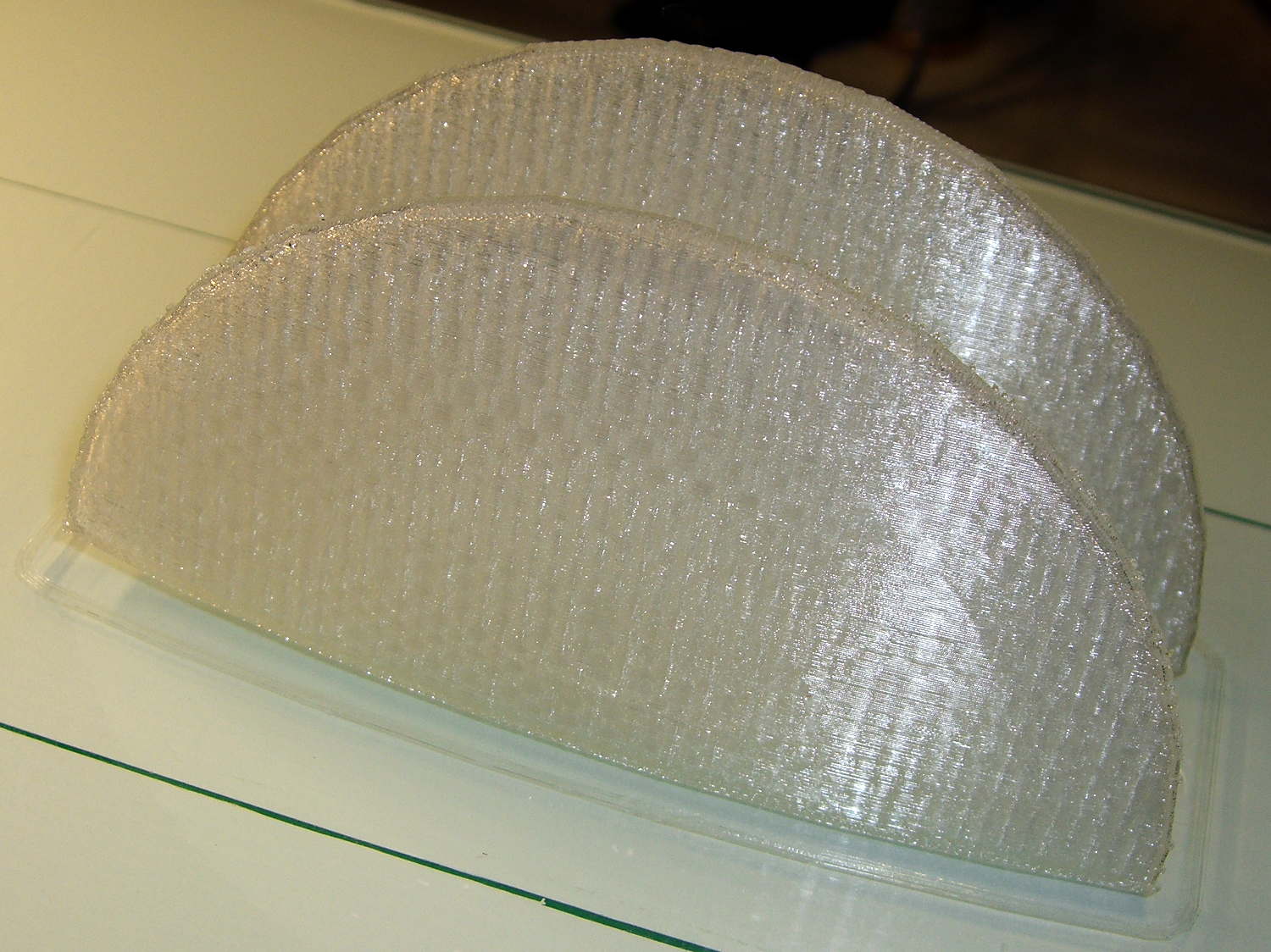
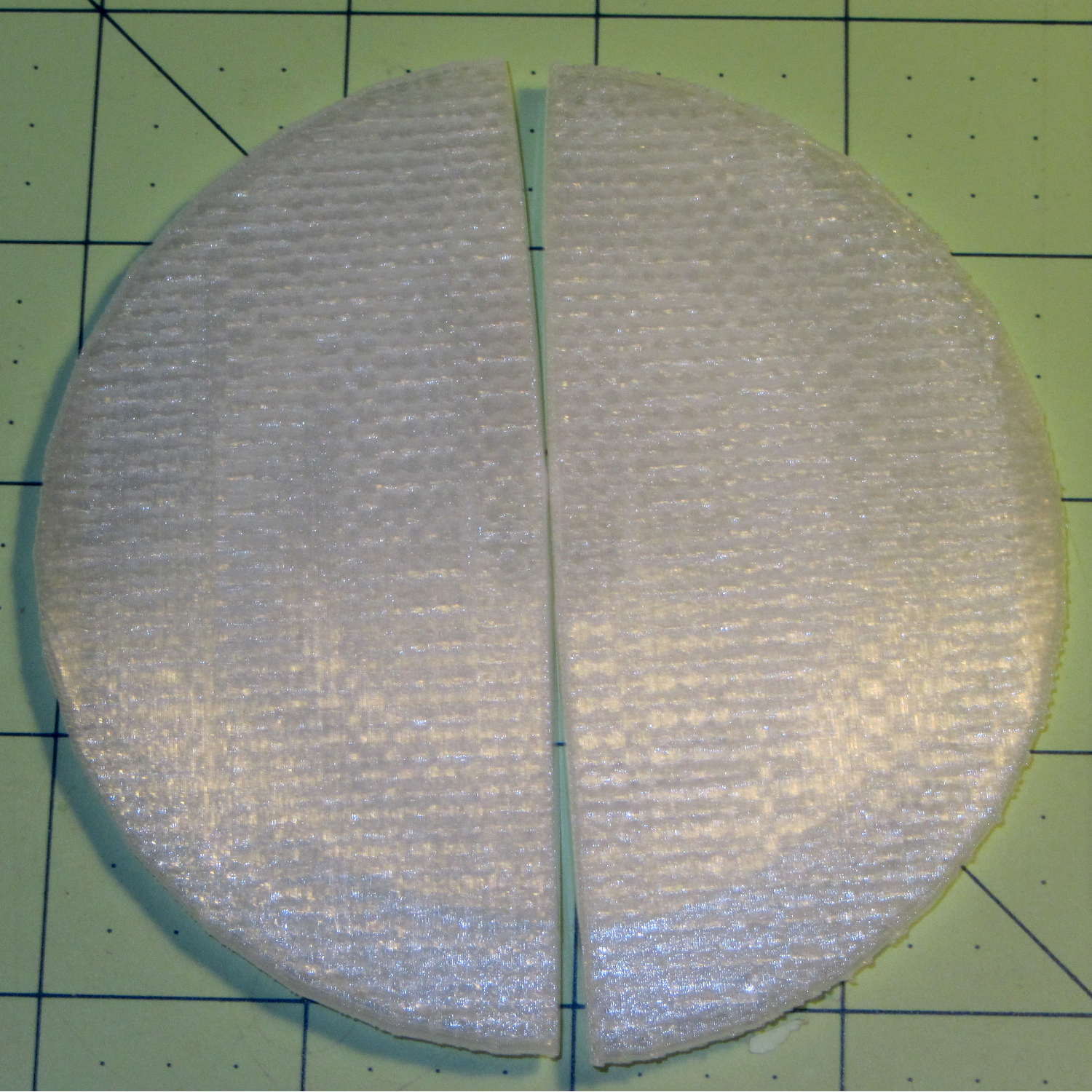
It’s basically a rounded slab with recesses for the PCB and clearance for solder-side components:

The solid model shows the screw holes sitting just about tangent to the PCB recess:

That’s using the new OpenSCAD with length scales along each axis; they won’t quite replace my layout grid over the XY plane, but they certainly don’t require as much computation.
I knew my lifetime supply of self-tapping hex head 4-40 screws would come in handy for something:

The program needs to know the PCB dimensions and how much clearance you want for the stuff hanging off the bottom:
PCBoard = [66,35,IntegerMultiple(1.8,ThreadThick)];

BottomParts = [[1.5,-1.0,0,0],	// xyz offset of part envelope
				[60.0,37.0,IntegerMultiple(3.0,ThreadThick)]];	// xyz envelope size (z should be generous)
That’s good enough for my simple needs.
The hole locations form a list-of-vectors that the code iterates through:
Holes = [			// PCB mounting screw holes: XY + rotation
		[Margin - ScrewOffset,MountBase[Y]/2,180/6],
		[MountBase[X] - Margin + ScrewOffset/sqrt(2),MountBase[Y] - Margin + ScrewOffset/sqrt(2),15],
		[MountBase[X] - Margin + ScrewOffset/sqrt(2),Margin - ScrewOffset/sqrt(2),-15],
		];

... snippage ...

for (h = Holes) {
	translate([h[X],h[Y],-Protrusion]) rotate(h[Z])
		PolyCyl(Tap4_40,MountBase[Z] + 2*Protrusion,6);
}
That’s the first occasion I’ve had to try iterating a list and It Just Worked; I must break the index habit. The newest OpenSCAD version has Python-ish list comprehensions which ought to come in handy for something.
The “Z coordinate” of each hole position gives its rotation, so I could snuggle them up a bit closer to the edge by forcing the proper polygon orientation. The square roots in the second two holes make them tangent to the corners of the PCB, rather than the sides, which wasn’t true for the first picture. Fortunately, the washer head of those screws turned out to be just big enough to capture the PCB anyway.
The OpenSCAD source code:
// PCB mounting bracket for XW029 DC-DC booster
// Ed Nisley - KE4ZNU - January 2015

Layout = "Build";			// PCB Block Mount Build

//- Extrusion parameters must match reality!
//  Print with 4 shells and 3 solid layers

ThreadThick = 0.20;
ThreadWidth = 0.40;

HoleWindage = 0.2;			// extra clearance

Protrusion = 0.1;			// make holes end cleanly

AlignPinOD = 1.70;			// assembly alignment pins: filament dia

function IntegerMultiple(Size,Unit) = Unit * ceil(Size / Unit);

X = 0;						// useful subscripts
Y = 1;
Z = 2;

//----------------------
// Dimensions

inch = 25.4;

Tap4_40 = 0.089 * inch;
Clear4_40 = 0.110 * inch;
Head4_40 = 0.211 * inch;
Head4_40Thick = 0.065 * inch;
Nut4_40Dia = 0.228 * inch;
Nut4_40Thick = 0.086 * inch;
Washer4_40OD = 0.270 * inch;
Washer4_40ID = 0.123 * inch;

PCBoard = [66,35,IntegerMultiple(1.8,ThreadThick)];

BottomParts = [[1.5,-1.0,0,0],				// xyz offset of part envelope
				[60.0,37.0,IntegerMultiple(3.0,ThreadThick)]];			// xyz envelope size (z should be generous)

Margin = IntegerMultiple(Washer4_40OD,ThreadWidth);

MountBase = [PCBoard[X] + 2*Margin,
			PCBoard[Y] + 2*Margin,
			IntegerMultiple(5.0,ThreadThick) + PCBoard[Z] + BottomParts[1][Z]
			];
echo("Mount base: ",MountBase);

ScrewOffset = Clear4_40/2;

Holes = [									// PCB mounting screw holes: XY + rotation
		[Margin - ScrewOffset,MountBase[Y]/2,180/6],
		[MountBase[X] - Margin + ScrewOffset/sqrt(2),MountBase[Y] - Margin + ScrewOffset/sqrt(2),15],
		[MountBase[X] - Margin + ScrewOffset/sqrt(2),Margin - ScrewOffset/sqrt(2),-15],
		];

CornerRadius = Washer4_40OD / 2;

//----------------------
// Useful routines

module PolyCyl(Dia,Height,ForceSides=0) {			// based on nophead's polyholes

  Sides = (ForceSides != 0) ? ForceSides : (ceil(Dia) + 2);

  FixDia = Dia / cos(180/Sides);

  cylinder(r=(FixDia + HoleWindage)/2,
           h=Height,
           $fn=Sides);
}

module ShowPegGrid(Space = 10.0,Size = 1.0) {

  RangeX = floor(100 / Space);
  RangeY = floor(125 / Space);

	for (x=[-RangeX:RangeX])
	  for (y=[-RangeY:RangeY])
		translate([x*Space,y*Space,Size/2])
		  %cube(Size,center=true);

}

//----------------------
// Build things

module PCB() {

	union() {
		cube(PCBoard);
		translate(BottomParts[X] - [0,0,BottomParts[1][Z]])
			cube(BottomParts[Y] + [0,0,Protrusion]);
	}

}

module Block() {
	translate([MountBase[X]/2,MountBase[Y]/2,0])
		hull()
			for (i = [-1,1], j = [-1,1])
				translate([i*(MountBase[X]/2 - CornerRadius),j*(MountBase[Y]/2 - CornerRadius)],0)
					cylinder(r=CornerRadius,h=MountBase[Z] - Protrusion,$fn=8*4);
}

module Mount() {

	difference() {
		Block();

		translate([MountBase[X]/2 - PCBoard[X]/2 + BottomParts[0][X] - Protrusion,
					-MountBase[Y]/2,
					MountBase[Z] - PCBoard[Z] - BottomParts[1][Z]])
			cube([BottomParts[1][X] + 2*Protrusion,
					2*MountBase[Y],
					2*BottomParts[1][Z]]);

		translate([MountBase[X]/2 - PCBoard[X]/2,		// PCB recess
					MountBase[Y]/2 - PCBoard[Y]/2,
					MountBase[Z] - PCBoard[Z]])
			PCB();
		for (h = Holes) {
			translate([h[X],h[Y],-Protrusion]) rotate(h[Z])
				PolyCyl(Tap4_40,MountBase[Z] + 2*Protrusion,6);
		}
	}

}

//ShowPegGrid();

if (Layout == "PCB")
	PCB();

if (Layout == "Block")
	Block();

if (Layout == "Mount")
	Mount();

if (Layout == "Build")
	translate([-MountBase[X]/2,-MountBase[Y]/2,0])
	Mount();