The Smell of Molten Projects in the Morning

Ed Nisley's Blog: Shop notes, electronics, firmware, machinery, 3D printing, laser cuttery, and curiosities. Contents: 100% human thinking, 0% AI slop.

Category: Machine Shop

Mechanical widgetry

  • LED Shoplight Conversion: Fluorescent Fixture Teardown

    The weakest fluorescent shop light fixtures always fail during cold weather (apart from the usual early tube failures) and this winter’s cold spells triggered the usual carnage, so I picked up half a dozen (cheap) 22 W LED T8 tubes and set about rewiring three defunct (cheap) fluorescent fixtures from the recycle heap. The new LED tubes run directly from the AC line; you must remove the fluorescent fixture’s ballasts / capacitors / starters and rewire the “tombstone” lampholders accordingly.

    The first challenge, as always, involved taking the fixtures apart. Turns out prying the endcap away from the fixture enough to clear the pair of bumps punched into the metal does the trick:

    Fluorescent Shoplights - endcap latches
    Fluorescent Shoplights – endcap latches

    Each endcap contains the ballast inductor / choke and power-factor correction capacitor for one tube. The inductors from one shoplight had a fancy plastic tab that might have held the capacitor in place, but that’s about the only difference:

    Fluorescent Shoplights - ballasts
    Fluorescent Shoplights – ballasts

    The 150 kΩ resistor has its leads twisted around the capacitor leads without benefit of that fancy solder stuff one might think necessary for a good connection.

    The capacitor contacts use the minimum possible amount of material:

    Fluorescent Shoplights - capacitor termination
    Fluorescent Shoplights – capacitor termination

    I think the caps use metallized Mylar film, but who knows?

    The inductors measure 280 mH and the caps a whopping 5 µF. I might trust the inductors in a low-voltage circuit, but the caps have no redeeming features and went directly to the trash.

    The starter PCB lived in the center of the fixture:

    Fluorescent Shoplights - starter circuit
    Fluorescent Shoplights – starter circuit

    I deliberately picked LED tubes with the AC line contact on one end and the neutral contact on the other, so as to not put line and neutral contacts in the same tombstone. After rewiring, the neutral endcap looks like this:

    Fluorescent Shoplights - neutral endcap
    Fluorescent Shoplights – neutral endcap

    The other endcap holds the power cord and has a green earth ground wire snaking out to a little tab passed into a slot punched in the metal case. I replaced the tab with an actual screw / solderless connector / toothed washer, but have no pix to show for it.

    The LED tubes run at 6500 K and contrast harshly with the warm-white tubes in the fluorescent shoplights. I went with the highest light output, because even the best (cheap) LED tubes produce barely half the output of the fluorescents: 2000-ish lumens vs 3900-ish.

  • Vacuum Tube LEDs: Platter Chassis

    Given that Greenlee chassis punches fit the ersatz vacuum tube sockets, this makes a certain perverse sense:

    Greenlee puch on hard drive platter
    Greenlee puch on hard drive platter

    This set of punches is probably worth its weight in, uh, tool steel, because Greenlee got out of the Radio Chassis Punch business quite a while ago:

    Greenlee 730 Radio Chassis Punch Assortment
    Greenlee 730 Radio Chassis Punch Assortment

    As far as a Greenlee punch is concerned, a hard drive platter looks a lot like thin aluminum sheet:

    Greenlee punched drive platter
    Greenlee punched drive platter

    I lathe-turned that white bushing to align the hard drive platter around the screw inside the punch. The right way to make that bushing in this day & age definitely involves 3D printing, but I was standing next to the lathe and spotted a nylon rod in the remnants bucket underneath.

    The inner ring crumples around the bushing inside the die, while the platter outside remains flat & undamaged through the entire experience.

    I match-marked the socket & “plate cap lead” holes on the punched platter and introduced it to Mr Drill Press, but the right way to do that for more than one socket / plate involves a Sherline mill fixture and some CNC.

    And then It Just Worked:

    Vacuum Tube LEDs - IBM 21HB5A drive platter socket
    Vacuum Tube LEDs – IBM 21HB5A drive platter socket

    That’s obviously a proof of concept; the socket rests on the desk with the rest of the tubes / sockets / Neopixels tailing off to the right. The plate cap lead should pass through a brass tube fitting on the platter, just for pretty.

    The 7- and 9-pin sockets have a raised disk that’s slightly smaller than the 25 mm hard drive hole; the easiest fix involves slightly enlarging the disk to match the hole. Although CDs / DVDs have a 15 mm hole and Greenlee punches work surprisingly well on polycarbonate, if I’m going to CNC-drill the screw / wire holes anyway, CNC milling the middle hole should go quickly and eliminate a messy manual process.

    Come to think of it, that big tube would look better in the middle of a DVD amid all those nice diffraction patterns from the RGB LEDs in the cap…


  • Sears Sewing Table: Sewing Machine Supports

    For reasons that should not require explanation by now, Mary just acquired a large sewing table (along with a Sears Kenmore Model 158 sewing machine that’s slightly older and fancier than the three we already have). The table has an opening fitted to the machine base, but the rubber pads atop the leveling screws had long since stiffened up and two screws were frozen in place. A few drops of penetrating oil released the screws and, mirable dictu, they have ordinary 6-32 threads.

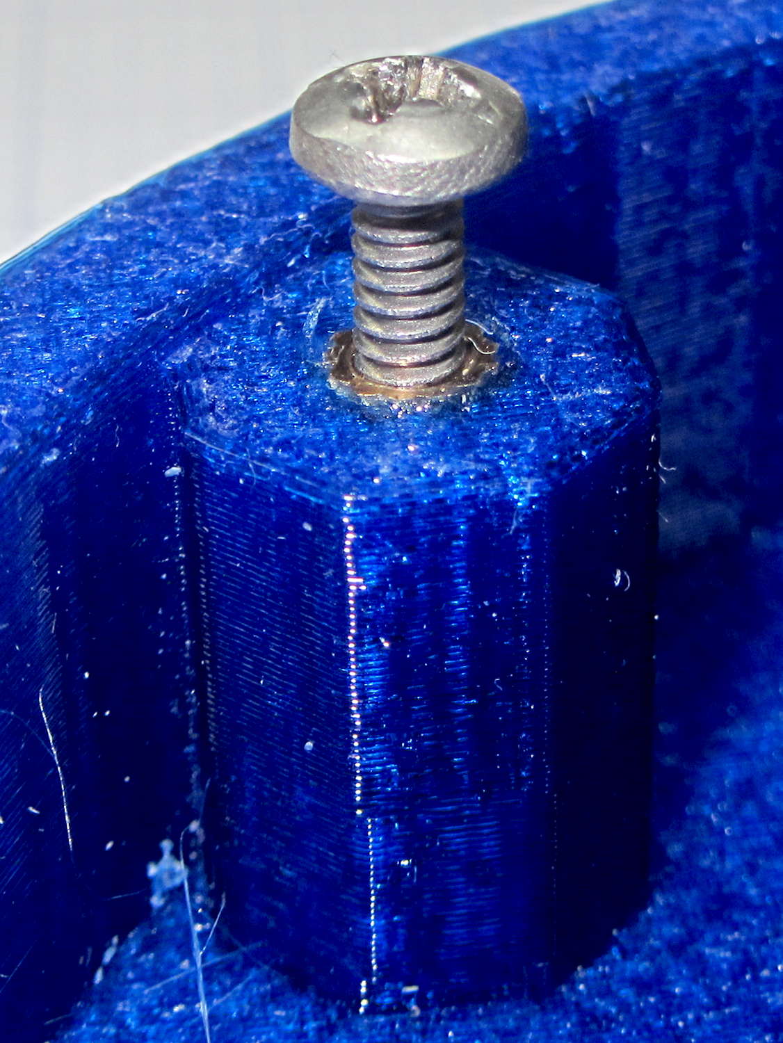
    Some rummaging turned up four PC case screws and soft caps intended for wire shelves, which easily combined into replacement machine supports:

    Sewing Machine Supports - inserting screws
    Sewing Machine Supports – inserting screws

    Once again, I’m using the drill press as a low-force arbor press, with a chunk of aluminum tubing to shove the screw flange into the slightly smaller plastic cap.

    Spun into their brackets, they look quite nice, not that anybody will ever see them:

    Sewing Machine Supports - installed
    Sewing Machine Supports – installed

    The new-to-us table replaces the incredible collection of junk previously supporting Machine #3. I tucked some plastic foam around the near and right edges to fill the small gaps and it fits well:

    Sewing Machine Supports - machine installed
    Sewing Machine Supports – machine installed

    Obviously, the foam will fall out whenever Mary lifts the machine to tinker with machinery under the platform, so we’ll see how often pins & needles slip through the cracks without the foam.

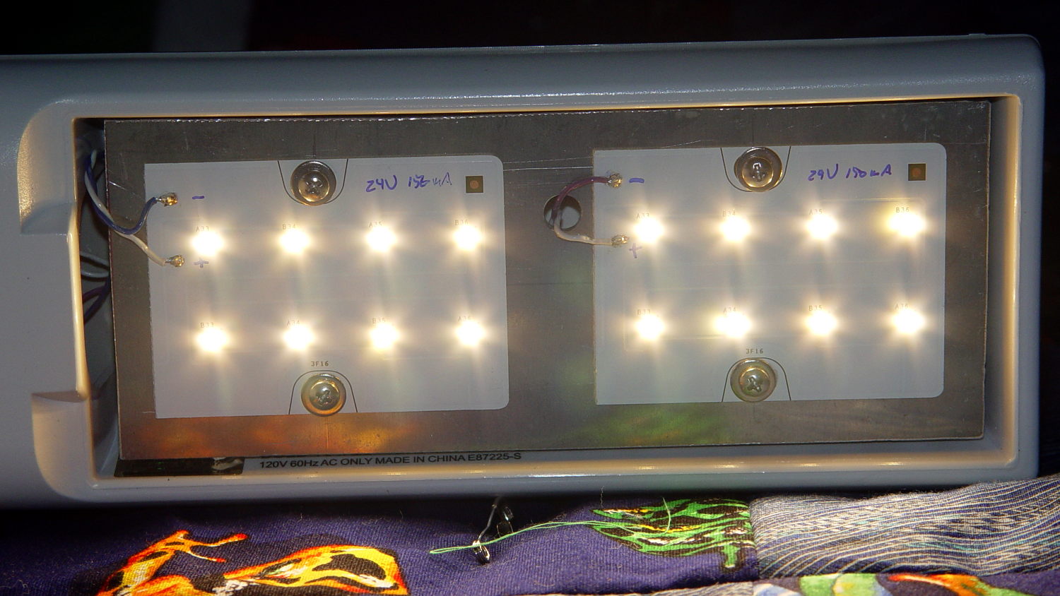
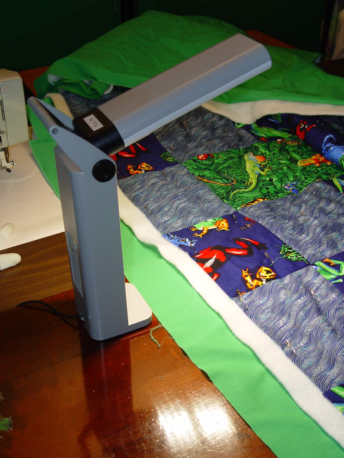
    That machine awaits a lighting update, because I’m awaiting some rectangular chip-on-board LED strips from halfway around the planet.

    Early reports concerning the sewing table seem promising…

  • Improved Lip Balm / Lipstick Holder

    Mary asked for a less angular version of the Lip Balm Holder, which gave me a chance to practice my list comprehension:

    Improved Lipstick and Balm Holder
    Improved Lipstick and Balm Holder

    You hand the OpenSCAD program a list of desired tube diameters in the order you want them, the program plunks the first one (ideally, the largest diameter) in the middle, arranges the others around it counterclockwise from left to right, then slips a lilypad under each tube.

    As long as you don’t ask for anything egregiously stupid, the results look reasonably good:

    Improved Lipstick and Balm Holder - 8 tubes
    Improved Lipstick and Balm Holder – 8 tubes

    As before, each tube length is 1.5 times its diameter; the lipsticks / balms fit loosely and don’t flop around.

    Given the tube diameters and the wall thickness, list comprehensions simplify creating lists of the radii from the center tube to each surrounding tube, the center-to-center distances between each of the outer tubes, and the angles between successive tubes:

    // per-tube info, first element forced to 0 to make entries match RawDia vector indexes
    
    Radius = [0, for (i=[1:NumTubes-1]) (TubeRad[0] + TubeRad[i] + Wall)];			// Tube[i] distance to center pointRadius = [0, for (i=[1:NumTubes-1]) (TubeRad[0] + TubeRad[i] + Wall)];			// Tube[i] distance to center point
    echo(str("Radius: ",Radius));
    
    CtrToCtr = [0, for (i=[1:NumTubes-2]) (TubeRad[i] + TubeRad[i+1] + Wall)];		// Tube[i] distance to Tube[i+1]
    echo(str("CtrToCtr: ",CtrToCtr));
    
    Angle = [0, for (i=[1:NumTubes-2]) acos((pow(Radius[i],2) + pow(Radius[i+1],2) - pow(CtrToCtr[i],2)) / (2 * Radius[i] * Radius[i+1]))];
    echo(str("Angle: ",Angle));
    
    TotalAngle = sumv(Angle,len(Angle)-1);
    echo(str("TotalAngle: ",TotalAngle));
    

    The angles come from the oblique triangle solution when you know all three sides (abc) and want the angle (C) between a and b:

    C = arccos( (a2 + b2 - c2) / (2ab) )

    Peering down inside, the Slic3r preview shows the lily pads are the tops of squashed spheres:

    Improved Lipstick and Balm Holder - Slic3r preview
    Improved Lipstick and Balm Holder – Slic3r preview

    The pads are 2.0 times the tube diameter, which seemed most pleasing to the eye. They top out at 2.0 mm thick, which might make the edges too thin for comfort.

    Update: Here’s what it looks like with a convex hull wrapped around all the lilypads:

    Improved Lipstick and Balm Holder - hulled base
    Improved Lipstick and Balm Holder – hulled base

    I’m awaiting reports from My Spies concerning the typical diameter(s) of lipstick tubes, then I’ll run off a prototype and see about the lily pad edges.

    The OpenSCAD source code as a GitHub gist:

    // Lipstick and Balm Tube Holder
    // Ed Nisley KE4ZNU – February 2016
    //- Extrusion parameters – must match reality!
    ThreadThick = 0.25;
    ThreadWidth = 0.40;
    function IntegerMultiple(Size,Unit) = Unit * ceil(Size / Unit);
    Protrusion = 0.1;
    HoleWindage = 0.2;
    //——
    // Dimensions
    RawDia = [26,21,19,17,19,21]; // actual tube diameters in desired order, center = largest first
    NumTubes = len(RawDia);
    Clearance = 2.0;
    TubeDia = [for (i=[0:NumTubes-1]) (RawDia[i] + Clearance)]; // actual tube diameters
    TubeRad = TubeDia / 2;
    echo(str("NumTubes: ",NumTubes));
    Wall = 2.0;
    BaseThick = 2.0;
    BaseFactor = 2.0;
    NumSides = 8*4;
    // per-tube info, first element forced to 0 to make entries match RawDia vector indexes
    Radius = [0, for (i=[1:NumTubes-1]) (TubeRad[0] + TubeRad[i] + Wall)]; // Tube[i] distance to center point
    echo(str("Radius: ",Radius));
    CtrToCtr = [0, for (i=[1:NumTubes-2]) (TubeRad[i] + TubeRad[i+1] + Wall)]; // Tube[i] distance to Tube[i+1]
    echo(str("CtrToCtr: ",CtrToCtr));
    Angle = [0, for (i=[1:NumTubes-2]) acos((pow(Radius[i],2) + pow(Radius[i+1],2) – pow(CtrToCtr[i],2)) / (2 * Radius[i] * Radius[i+1]))];
    echo(str("Angle: ",Angle));
    TotalAngle = sumv(Angle,len(Angle)-1);
    echo(str("TotalAngle: ",TotalAngle));
    //———————-
    // Useful routines
    // vector sum cribbed from doc
    function sumv(v,i,s=0) = (i==s ? v[i] : v[i] + sumv(v,i-1,s));
    //———————-
    //- Build it
    for (i=[0:NumTubes-1])
    rotate(90 – TotalAngle/2 + sumv(Angle, (i>0) ? (i-1) : 0))
    translate([Radius[i],0,0]) {
    resize([0,0,2*BaseThick]) // bases
    difference() {
    sphere(r=BaseFactor*TubeRad[i],$fn=NumSides);
    translate([0,0,-BaseFactor*TubeDia[i]])
    cube(2*BaseFactor*TubeDia[i],center=true);
    }
    difference() { // tubes
    cylinder(r=TubeRad[i] + Wall,h=1.5*TubeDia[i] + BaseThick,$fn=NumSides);
    cylinder(d=TubeDia[i],h=1.5*TubeDia[i] + BaseThick + Protrusion,$fn=NumSides);
    }
    }
  • Knurled Inch Inserts

    Tagging along behind the metric inserts, a sack of knurled brass inch-size screw inserts arrived:

    Threaded Inserts - metric and inch
    Threaded Inserts – metric and inch

    The nice stainless steel screws on the right range from 4-40 to 10-32, which suffice for nearly everything I build around here.

    Unlike the splined metric inserts on the left, these inserts have actual knurls and ridges that should hold them firmly in place. The specs give hard-inch dimensions, of course, that (seem to) correspond to the root diameter of the knurls. You can find nice engineering drawings of precise tapered holes (by drilling down into the Heat-Set Inserts for Plastics item on that page), but a few metric measurements of the actual parts on hand should suffice for my simple needs.

    Thread: overall length x small rim OD x (knurl length x larger knurl OD)

    • 4-40: 5.8 x 3.9 x (4.0 x 4.6)
    • 6-32: 7.1 x 4.7 x (4.6 x 5.5)
    • 8-32: 8.1 x 5.5 x (5.9 x 6.3)
    • 10-32: 9.5 x 6.3 x (7.0 x 7.1)

    Rather than fussing with a tapered hole, just punch a cylinder with the small rim OD (to clear the screw) through the part and put a cylinder with the knurl OD x length at the surface.

    Using cylinders without diameter correction will make them slightly undersized for heat bonding. The usual 3D printing tolerances don’t justify anything fussier than that.

    Using PolyCyl diameter correction will make the holes nearly spot on for epoxy bonding: butter ’em up, ram ’em in, pause for curing, done.

    That’s the plan, anyhow…

  • Vacuum Tube LEDs: Ersatz Heat Sink Plate Cap

    I wanted a slightly larger “plate cap” to fit a big incandescent bulb and it seemed a fake heatsink might add gravitas to the proceedings:

    Vacuum Tube LEDs - large incandescent bulb
    Vacuum Tube LEDs – large incandescent bulb

    Yeah, that antique ceramic socket holds the bulb at a rakish angle. Worse, even though I painstakingly laid out the position of the heatsink atop the bulb, it’s visibly off-center. Which wouldn’t be so bad, had I not epoxied the damn thing in place.

    After reaming out the M2’s filament drive, the entire blue base printed without incident.

    A closer look at the cap:

    Vacuum Tube LEDs - ersatz heatsink plate cap
    Vacuum Tube LEDs – ersatz heatsink plate cap

    Memo to Self: Next time, line it up with the vertical glass support inside the bulb and ignore the external evidence.

    The boss has a hole for the braid-enclosed cable to the knockoff Neopixel:

    Vacuum Tube Lights - finned cap - Slic3r preview
    Vacuum Tube Lights – finned cap – Slic3r preview

    The cupped surface perfectly fits the bulb’s 3.75 inch diameter. While you wouldn’t mill out a real heatsink, it definitely looks better this way and (alas) gives the epoxy more footprint for a better grip.

    I built the fins with a 1/8 inch cutter in mind, so the fin root radius allows for a G3/G3 arc without gouging. I doubt machining a fake heatsink from aluminum makes any sense, but the cheap extruded heatsinks on eBay don’t look very good. Plus, they sport completely unnecessary tapped holes for LED mounts and suchlike.

    A cross-section shows the wiring channel and cable entry:

    Vacuum Tube Lights - fin cap solid model - section
    Vacuum Tube Lights – fin cap solid model – section

    I epoxied the Neopixel in place, applied double-sided carpet tape to the whole thing, then painstakingly trimmed around the fins with an Xacto knife:

    Vacuum Tube LEDs - Ersatz Heatsink plate cap - tape
    Vacuum Tube LEDs – Ersatz Heatsink plate cap – tape

    That looked better from the top side (where it was completely hidden) and came heartbreakingly close to working, but after about a day the cable + braid put enough torque on the cap to peel it off the bulb. Obviously, the tape holds much less enthusiastically after that.

    Part of the problem came from the cable’s rather sharp angle just outside the cap:

    Vacuum Tube LEDs - Ersatz Heatink plate cap - detail
    Vacuum Tube LEDs – Ersatz Heatink plate cap – detail

    Rakish angle, indeed. Two of ’em, in fact.

    Unlike the smaller cap on the halogen bulb, this time I didn’t bother with a brass tube ferrule, mostly to see how it looks. I think it came out OK and the black braid looks striking in person. Conversely, a touch of brass never detracts from the appearance.

    Obviously, the cable wasn’t long enough, either. Part of that problem came from underestimating the braid length: it shortens dramatically when slipped over the cable, even when you expect shortening. Somehow I managed to overlook that, despite cutting the cable quite long enough, thankyouverymuch. There’s a tradeoff between gentle angles and having the cable stick out too far for comfort.

    Memo to Self: Use a cable at least four inches longer than necessary, measure the combined cable + braid assembly after screwing the bulb in the socket, and don’t epoxy anything before all the parts are ready for assembly.

    That’s why it’s a prototype made out of blue PETG…

    Protip: running old ceramic sockets through the dishwasher greatly simplifies their subsequent cleanup.

    All in all, I like it.

    The OpenSCAD source code as a GitHub gist:

    // Vacuum Tube LED Lights
    // Ed Nisley KE4ZNU January 2016
    Layout = "FinCap"; // Cap LampBase USBPort Socket(s) (Build)FinCap
    Section = true; // cross-section the object
    Support = true;
    //- Extrusion parameters must match reality!
    ThreadThick = 0.25;
    ThreadWidth = 0.40;
    HoleWindage = 0.2;
    Protrusion = 0.1; // make holes end cleanly
    inch = 25.4;
    function IntegerMultiple(Size,Unit) = Unit * ceil(Size / Unit);
    //———————-
    // Dimensions
    // https://en.wikipedia.org/wiki/Tube_socket#Summary_of_Base_Details
    T_NAME = 0; // common name
    T_NUMPINS = 1; // total, with no allowance for keying
    T_PINBCD = 2; // tube pin circle diameter
    T_PINOD = 3; // … diameter
    T_PINLEN = 4; // … length (overestimate)
    T_HOLEOD = 5; // nominal panel hole from various sources
    T_PUNCHOD = 6; // panel hole optimized for inch-size Greenlee punches
    T_TUBEOD = 7; // envelope or base diameter
    T_PIPEOD = 8; // light pipe from LED to tube base
    T_SCREWOC = 9; // mounting screw holes
    // Name pins BCD dia length hole punch env pipe screw
    TubeData = [
    ["Mini7", 8, 9.53, 1.016, 7.0, 16.0, 11/16 * inch, 18.0, 5.0, 22.5],
    ["Octal", 8, 17.45, 2.36, 10.0, 36.2, (8 + 1)/8 * inch, 32.0, 11.5, 39.0],
    ["Noval", 10, 11.89, 1.1016, 7.0, 22.0, 7/8 * inch, 21.0, 5.0, 28.0],
    ["Duodecar", 13, 19.10, 1.05, 9.0, 32.0, 1.25 * inch, 38.0, 12.5, 39.0],
    ];
    ID = 0;
    OD = 1;
    LENGTH = 2;
    Pixel = [7.0,10.0,3.0]; // ID = contact patch, OD = PCB dia, LENGTH = overall thickness
    Nut = [3.5,8.0,3.0]; // socket mounting nut recess
    BaseShim = 2*ThreadThick; // between pin holes and pixel top
    SocketFlange = 2.0; // rim around socket below punchout
    PanelThick = 2.0; // socket extension through punchout
    //———————-
    // Useful routines
    module PolyCyl(Dia,Height,ForceSides=0) { // based on nophead's polyholes
    Sides = (ForceSides != 0) ? ForceSides : (ceil(Dia) + 2);
    FixDia = Dia / cos(180/Sides);
    cylinder(r=(FixDia + HoleWindage)/2,h=Height,$fn=Sides);
    }
    //———————-
    // Tube cap
    CapTube = [4.0,3/16 * inch,10.0]; // brass tube for flying lead to cap LED
    CapSize = [Pixel[ID],(Pixel[OD] + 3.0),(CapTube[OD] + 2*Pixel[LENGTH])];
    CapSides = 6*4;
    module Cap() {
    difference() {
    union() {
    cylinder(d=CapSize[OD],h=(CapSize[LENGTH]),$fn=CapSides); // main cap body
    translate([0,0,CapSize[LENGTH]]) // rounded top
    scale([1.0,1.0,0.65])
    sphere(d=CapSize[OD]/cos(180/CapSides),$fn=CapSides); // cos() fixes slight undersize vs cylinder
    cylinder(d1=(CapSize[OD] + 2*3*ThreadWidth),d2=CapSize[OD],h=1.5*Pixel[LENGTH],$fn=CapSides); // skirt
    }
    translate([0,0,-Protrusion]) // bore for wiring to LED
    PolyCyl(CapSize[ID],(CapSize[LENGTH] + 3*ThreadThick + Protrusion),CapSides);
    translate([0,0,-Protrusion]) // PCB recess with clearance for tube dome
    PolyCyl(Pixel[OD],(1.5*Pixel[LENGTH] + Protrusion),CapSides);
    translate([0,0,(1.5*Pixel[LENGTH] – Protrusion)]) // small step + cone to retain PCB
    cylinder(d1=(Pixel[OD]/cos(180/CapSides)),d2=Pixel[ID],h=(Pixel[LENGTH] + Protrusion),$fn=CapSides);
    translate([0,0,(CapSize[LENGTH] – CapTube[OD]/(2*cos(180/8)))]) // hole for brass tube holding wire loom
    rotate([90,0,0]) rotate(180/8)
    PolyCyl(CapTube[OD],CapSize[OD],8);
    }
    }
    //———————-
    // Heatsink tube cap
    CableOD = 3.5; // cable + braid diameter
    BulbOD = 3.75 * inch; // bulb OD; use 10 inches for flat
    FinCutterOD = 1/8 * inch;
    echo(str("Fin Cutter: ",FinCutterOD));
    FinSides = 2*4;
    FinCapSize = [(Pixel[OD] + 2*FinCutterOD),30.0,(10.0 + 2*Pixel[LENGTH])];
    BulbRadius = BulbOD / 2;
    BulbDepth = BulbRadius – sqrt(pow(BulbRadius,2) – pow(FinCapSize[OD],2)/4);
    echo(str("Bulb OD: ",BulbOD," recess: ",BulbDepth));
    module FinCap() {
    NumFins = floor(PI*FinCapSize[ID] / (2*FinCutterOD));
    FinAngle = 360 / NumFins;
    echo(str("NumFins: ",NumFins," angle: ",FinAngle," deg"));
    difference() {
    union() {
    cylinder(d=FinCapSize[ID],h=FinCapSize[LENGTH],$fn=2*NumFins); // main body
    for (i = [0:NumFins – 1]) // fins
    rotate(i * FinAngle)
    hull() {
    translate([FinCapSize[ID]/2,0,0])
    rotate(180/FinSides)
    cylinder(d=FinCutterOD,h=FinCapSize[LENGTH],$fn=FinSides);
    translate([(FinCapSize[OD] – FinCutterOD)/2,0,0])
    rotate(180/FinSides)
    cylinder(d=FinCutterOD,h=FinCapSize[LENGTH],$fn=FinSides);
    }
    rotate(FinAngle/2) // cable entry boss
    translate([FinCapSize[ID]/2,0,FinCapSize[LENGTH]/2])
    cube([FinCapSize[OD]/4,FinCapSize[OD]/4,FinCapSize[LENGTH]],center=true);
    }
    for (i = [1:NumFins – 1]) // fin inner gullets, omit cable entry side
    rotate(i * FinAngle + FinAngle/2) // joint isn't quite perfect, but OK
    translate([FinCapSize[ID]/2,0,-Protrusion])
    rotate(0*180/FinSides)
    cylinder(d=FinCutterOD/cos(180/FinSides),h=(FinCapSize[LENGTH] + 2*Protrusion),$fn=FinSides);
    translate([0,0,-Protrusion]) // PCB recess
    PolyCyl(Pixel[OD],(1.5*Pixel[LENGTH] + Protrusion),FinSides);
    PolyCyl(Pixel[ID],(FinCapSize[LENGTH] – 3*ThreadThick),FinSides); // bore for LED wiring
    translate([0,0,(FinCapSize[LENGTH] – 3*ThreadThick – 2*CableOD/(2*cos(180/8)))]) // cable inlet
    rotate(FinAngle/2) rotate([0,90,0]) rotate(180/8)
    PolyCyl(CableOD,FinCapSize[OD],8);
    if (BulbOD <= 10.0 * inch) // curve for top of bulb
    translate([0,0,-(BulbRadius – BulbDepth + 2*ThreadThick)]) // … slightly flatten tips
    sphere(d=BulbOD,$fn=16*FinSides);
    }
    }
    //———————-
    // Aperture for USB-to-serial adapter snout
    // These are all magic numbers, of course
    module USBPort() {
    translate([0,28.0])
    rotate([90,0,0])
    linear_extrude(height=28.0)
    polygon(points=[
    [0,0],
    [8.0,0],
    [8.0,4.0],
    // [4.0,4.0],
    [4.0,6.5],
    [-4.0,6.5],
    // [-4.0,4.0],
    [-8.0,4.0],
    [-8.0,0],
    ]);
    }
    //———————-
    // Box for Leviton ceramic lamp base
    module LampBase() {
    Bottom = 3.0;
    Base = [4.0*inch,4.5*inch,20.0 + Bottom];
    Sides = 12*4;
    Retainer = [3.5,11.0,1.0]; // flat fiber washer holding lamp base screws in place
    StudSides = 8;
    StudOC = 3.5 * inch;
    Stud = [0.107 * inch, // 6-32 mounting screws
    min(15.0,1.5*(Base[ID] – StudOC)/cos(180/StudSides)), // OD = big enough to merge with walls
    (Base[LENGTH] – Retainer[LENGTH])]; // leave room for retainer
    union() {
    difference() {
    rotate(180/Sides)
    cylinder(d=Base[OD],h=Base[LENGTH],$fn=Sides);
    rotate(180/Sides)
    translate([0,0,Bottom])
    cylinder(d=Base[ID],h=Base[LENGTH],$fn=Sides);
    translate([0,-Base[OD]/2,Bottom + 1.2]) // mount on double-sided foam tape
    rotate(0)
    USBPort();
    }
    for (i = [-1,1])
    translate([i*StudOC/2,0,0])
    rotate(180/StudSides)
    difference() {
    # cylinder(d=Stud[OD],h=Stud[LENGTH],$fn=StudSides);
    translate([0,0,Bottom])
    PolyCyl(Stud[ID],(Stud[LENGTH] – (Bottom – Protrusion)),6);
    }
    }
    }
    //———————-
    // Tube Socket
    module Socket(Name = "Mini7") {
    NumSides = 6*4;
    Tube = search([Name],TubeData,1,0)[0];
    echo(str("Building ",TubeData[Tube][0]," socket"));
    echo(str(" Punch: ",TubeData[ID][T_PUNCHOD]," mm = ",TubeData[ID][T_PUNCHOD]/inch," inch"));
    echo(str(" Screws: ",TubeData[ID][T_SCREWOC]," mm =",TubeData[ID][T_SCREWOC]/inch," inch OC"));
    OAH = Pixel[LENGTH] + BaseShim + TubeData[Tube][T_PINLEN];
    BaseHeight = OAH – PanelThick;
    difference() {
    union() {
    linear_extrude(height=BaseHeight)
    hull() {
    circle(d=(TubeData[Tube][T_PUNCHOD] + 2*SocketFlange),$fn=NumSides);
    for (i=[-1,1])
    translate([i*TubeData[Tube][T_SCREWOC]/2,0])
    circle(d=2*Nut[OD],$fn=NumSides);
    }
    cylinder(d=TubeData[Tube][T_PUNCHOD],h=OAH,$fn=NumSides);
    }
    for (i=[0:(TubeData[Tube][T_NUMPINS] – 1)]) // tube pins
    rotate(i*360/TubeData[Tube][T_NUMPINS])
    translate([TubeData[Tube][T_PINBCD]/2,0,(OAH – TubeData[Tube][T_PINLEN])])
    rotate(180/4)
    PolyCyl(TubeData[Tube][T_PINOD],(TubeData[Tube][T_PINLEN] + Protrusion),4);
    for (i=[-1,1]) // mounting screw holes & nut traps
    translate([i*TubeData[Tube][T_SCREWOC]/2,0,-Protrusion]) {
    PolyCyl(Nut[OD],(Nut[LENGTH] + Protrusion),6);
    PolyCyl(Nut[ID],(OAH + 2*Protrusion),6);
    }
    translate([0,0,-Protrusion]) { // LED recess
    PolyCyl(Pixel[OD],(Pixel[LENGTH] + Protrusion),8);
    }
    translate([0,0,(Pixel[LENGTH] – Protrusion)]) { // light pipe
    rotate(180/TubeData[Tube][T_NUMPINS])
    PolyCyl(TubeData[Tube][T_PIPEOD],(OAH + 2*Protrusion),TubeData[Tube][T_NUMPINS]);
    }
    }
    // Totally ad-hoc support structures …
    if (Support) {
    color("Yellow") {
    for (i=[-1,1]) // nut traps
    translate([i*TubeData[Tube][T_SCREWOC]/2,0,(Nut[LENGTH] – ThreadThick)/2])
    for (a=[0:5])
    rotate(a*30 + 15)
    cube([2*ThreadWidth,0.9*Nut[OD],(Nut[LENGTH] – ThreadThick)],center=true);
    if (Pixel[OD] > TubeData[Tube][T_PIPEOD]) // support pipe only if needed
    translate([0,0,(Pixel[LENGTH] – ThreadThick)/2])
    for (a=[0:7])
    rotate(a*22.5)
    cube([2*ThreadWidth,0.9*Pixel[OD],(Pixel[LENGTH] – ThreadThick)],center=true);
    }
    }
    }
    //———————-
    // Build it
    if (Layout == "Cap") {
    if (Section)
    difference() {
    Cap();
    translate([-CapSize[OD],0,CapSize[LENGTH]])
    cube([2*CapSize[OD],2*CapSize[OD],3*CapSize[LENGTH]],center=true);
    }
    else
    Cap();
    }
    if (Layout == "FinCap") {
    if (Section) render(convexity=5)
    difference() {
    FinCap();
    // translate([0,-FinCapSize[OD],FinCapSize[LENGTH]])
    // cube([2*FinCapSize[OD],2*FinCapSize[OD],3*FinCapSize[LENGTH]],center=true);
    translate([-FinCapSize[OD],0,FinCapSize[LENGTH]])
    cube([2*FinCapSize[OD],2*FinCapSize[OD],3*FinCapSize[LENGTH]],center=true);
    }
    else
    FinCap();
    }
    if (Layout == "BuildFinCap")
    translate([0,0,FinCapSize[LENGTH]])
    rotate([180,0,0])
    FinCap();
    if (Layout == "LampBase")
    LampBase();
    if (Layout == "USBPort")
    USBPort();
    if (Layout == "Socket")
    if (Section) {
    difference() {
    Socket();
    translate([-100/2,0,-Protrusion])
    cube([100,50,50],center=false);
    }
    }
    else
    Socket();
    if (Layout == "Sockets") {
    translate([0,50,0])
    Socket("Mini7");
    translate([0,20,0])
    Socket("Octal");
    translate([0,-15,0])
    Socket("Duodecar");
    translate([0,-50,0])
    Socket("Noval");
    }
  • Vacuum Tube LEDs: First Light!

    A test lashup to see how it all works, with an ersatz plate cap atop the IBM 21HB5A Beam Power tube on the far right end:

    Vacuum Tube LEDs - test lashup
    Vacuum Tube LEDs – test lashup

    Those sockets must mount in a chassis, not flop around loose on the cable.

    I hacked the code out of the Hard Drive Platter Mood Light; there’s a lot to not like about what’s left and I must rethink the overall structure. The colors now run an order of magnitude faster than the Platter Mood Light, with a 90° phase angle between successive Neopixels.

    The mica spacers in the 12AT7 Dual Triode tube (second in the sequence, Noval socket) look cool & crystalline:

    Vacuum Tube LEDs - Noval tube - blue phase
    Vacuum Tube LEDs – Noval tube – blue phase

    When the red phase comes around, it becomes a firebottle:

    Vacuum Tube LEDs - Noval tube - red phase
    Vacuum Tube LEDs – Noval tube – red phase

    With a touch of fire in its hole, the IBM 21HB5A Beam Power tube looks just flat-out gorgeous, despite that translucent blue plate cap:

    Vacuum Tube LEDs - IBM 21HB5A Beam Power Tube - violet amber phase
    Vacuum Tube LEDs – IBM 21HB5A Beam Power Tube – violet amber phase

    Cool green works pretty well:

    Vacuum Tube LEDs - IBM 21HB5A Beam Power Tube - green violet phase
    Vacuum Tube LEDs – IBM 21HB5A Beam Power Tube – green violet phase

    If you wait long enough, it’ll probably turn True IBM Blue.

    This worked out even better than I expected!

    The Arduino source code as a GitHub gist:

    // Neopixel lighting for multiple vacuum tubes
    // Ed Nisley – KE4ANU – January 2015
    #include <Adafruit_NeoPixel.h>
    //———-
    // Pin assignments
    const byte PIN_NEO = A3; // DO – data out to first Neopixel
    const byte PIN_HEARTBEAT = 13; // DO – Arduino LED
    //———-
    // Constants
    #define UPDATEINTERVAL 25ul
    const unsigned long UpdateMS = UPDATEINTERVAL – 1ul; // update LEDs only this many ms apart minus loop() overhead
    // number of steps per cycle, before applying prime factors
    #define RESOLUTION 100
    // phase difference between tubes for slowest color
    #define BASEPHASE (PI/4.0)
    // number of LED strips around each tube
    #define LEDSTRIPCOUNT 1
    // number of LEDs per strip
    #define LEDSTRINGCOUNT 5
    // want to randomize the startup a little?
    #define RANDOMIZE true
    //———-
    // Globals
    // instantiate the Neopixel buffer array
    Adafruit_NeoPixel strip = Adafruit_NeoPixel(LEDSTRIPCOUNT * LEDSTRINGCOUNT, PIN_NEO, NEO_GRB + NEO_KHZ800);
    uint32_t FullWhite = strip.Color(255,255,255);
    uint32_t FullOff = strip.Color(0,0,0);
    struct pixcolor_t {
    byte Prime;
    unsigned int NumSteps;
    unsigned int Step;
    float StepSize;
    float TubePhase;
    byte MaxPWM;
    };
    // colors in each LED
    enum pixcolors {RED, GREEN, BLUE, PIXELSIZE};
    struct pixcolor_t Pixels[PIXELSIZE]; // all the data for each pixel color intensity
    byte Map[LEDSTRINGCOUNT][LEDSTRIPCOUNT] = {{0},{1},{2},{3},{4}}; // pixel IDs around each tube, bottom to top.
    unsigned long MillisNow;
    unsigned long MillisThen;
    //– Figure PWM based on current state
    byte StepColor(byte Color, float Phi) {
    byte Value;
    Value = (Pixels[Color].MaxPWM / 2.0) * (1.0 + sin(Pixels[Color].Step * Pixels[Color].StepSize + Phi));
    // Value = (Value) ? Value : Pixels[Color].MaxPWM; // flash at dimmest points
    // printf("C: %d Phi: %d Value: %d\r\n",Color,(int)(Phi*180.0/PI),Value);
    return Value;
    }
    //– Helper routine for printf()
    int s_putc(char c, FILE *t) {
    Serial.write(c);
    }
    //——————
    // Set the mood
    void setup() {
    pinMode(PIN_HEARTBEAT,OUTPUT);
    digitalWrite(PIN_HEARTBEAT,LOW); // show we arrived
    Serial.begin(57600);
    fdevopen(&s_putc,0); // set up serial output for printf()
    printf("Multiple Vacuum Tube Mood Light with Neopixels\r\nEd Nisley – KE4ZNU – January 2016\r\n");
    /// set up Neopixels
    strip.begin();
    strip.show();
    // lamp test: run a brilliant white dot along the length of the strip
    printf("Lamp test: walking white\r\n");
    strip.setPixelColor(0,FullWhite);
    strip.show();
    delay(500);
    for (int i=1; i<strip.numPixels(); i++) {
    digitalWrite(PIN_HEARTBEAT,HIGH);
    strip.setPixelColor(i-1,FullOff);
    strip.setPixelColor(i,FullWhite);
    strip.show();
    digitalWrite(PIN_HEARTBEAT,LOW);
    delay(500);
    }
    strip.setPixelColor(strip.numPixels() – 1,FullOff);
    strip.show();
    delay(500);
    // fill the layers
    printf(" … fill using Map array\r\n");
    for (int i=0; i < LEDSTRINGCOUNT; i++) { // for each layer
    digitalWrite(PIN_HEARTBEAT,HIGH);
    for (int j=0; j < LEDSTRIPCOUNT; j++) { // spread color around the layer
    strip.setPixelColor(Map[i][j],FullWhite);
    strip.show();
    delay(250);
    }
    digitalWrite(PIN_HEARTBEAT,LOW);
    }
    // clear to black
    printf(" … clear\r\n");
    for (int i=0; i < LEDSTRINGCOUNT; i++) { // for each layer
    digitalWrite(PIN_HEARTBEAT,HIGH);
    for (int j=0; j < LEDSTRIPCOUNT; j++) { // spread color around the layer
    strip.setPixelColor(Map[i][j],FullOff);
    strip.show();
    delay(250);
    }
    digitalWrite(PIN_HEARTBEAT,LOW);
    }
    delay(1000);
    // set up the color generators
    MillisNow = MillisThen = millis();
    if (RANDOMIZE)
    randomSeed(MillisNow + analogRead(7));
    else
    printf("Start not randomized\r\n");
    printf("First random number: %ld\r\n",random(10));
    Pixels[RED].Prime = 7;
    Pixels[GREEN].Prime = 5;
    Pixels[BLUE].Prime = 3;
    printf("Primes: (%d,%d,%d)\r\n",Pixels[RED].Prime,Pixels[GREEN].Prime,Pixels[BLUE].Prime);
    unsigned int TubeSteps = (unsigned int) ((BASEPHASE / TWO_PI) *
    RESOLUTION * (unsigned int) max(max(Pixels[RED].Prime,Pixels[GREEN].Prime),Pixels[BLUE].Prime));
    printf("Tube phase offset: %d deg = %d steps\r\n",(int)(BASEPHASE*(360.0/TWO_PI)),TubeSteps);
    Pixels[RED].MaxPWM = 255;
    Pixels[GREEN].MaxPWM = 128;
    Pixels[BLUE].MaxPWM = 255;
    for (byte c=0; c < PIXELSIZE; c++) {
    Pixels[c].NumSteps = RESOLUTION * (unsigned int) Pixels[c].Prime;
    Pixels[c].Step = (RANDOMIZE) ? random(Pixels[c].NumSteps) : (3*Pixels[c].NumSteps)/4;
    Pixels[c].StepSize = TWO_PI / Pixels[c].NumSteps; // in radians per step
    Pixels[c].TubePhase = TubeSteps * Pixels[c].StepSize; // radians per tube
    printf("c: %d Steps: %d Init: %d",c,Pixels[c].NumSteps,Pixels[c].Step);
    printf(" PWM: %d Phi %d deg\r\n",Pixels[c].MaxPWM,(int)(Pixels[c].TubePhase*(360.0/TWO_PI)));
    }
    }
    //——————
    // Run the mood
    void loop() {
    MillisNow = millis();
    if ((MillisNow – MillisThen) > UpdateMS) {
    digitalWrite(PIN_HEARTBEAT,HIGH);
    for (byte c=0; c < PIXELSIZE; c++) { // step to next increment in each color
    if (++Pixels[c].Step >= Pixels[c].NumSteps) {
    Pixels[c].Step = 0;
    printf("Cycle %d steps %d at %8ld delta %ld ms\r\n",c,Pixels[c].NumSteps,MillisNow,(MillisNow – MillisThen));
    }
    }
    for (int i=0; i < LEDSTRINGCOUNT; i++) { // for each layer
    byte Value[PIXELSIZE];
    for (byte c=0; c < PIXELSIZE; c++) { // … for each color
    Value[c] = StepColor(c,-i*Pixels[c].TubePhase); // figure new PWM value
    // Value[c] = (c == RED && Value[c] == 0) ? Pixels[c].MaxPWM : Value[c]; // flash highlight for tracking
    }
    uint32_t UniColor = strip.Color(Value[RED],Value[GREEN],Value[BLUE]);
    if (false && (i == 0))
    printf("L: %d C: %08lx\r\n",i,UniColor);
    for (int j=0; j < LEDSTRIPCOUNT; j++) { // fill layer with color
    strip.setPixelColor(Map[i][j],UniColor);
    }
    }
    strip.show();
    MillisThen = MillisNow;
    digitalWrite(PIN_HEARTBEAT,LOW);
    }
    }
    view raw MultiTube.ino hosted with ❤ by GitHub