The Smell of Molten Projects in the Morning

Ed Nisley's Blog: Shop notes, electronics, firmware, machinery, 3D printing, laser cuttery, and curiosities. Contents: 100% human thinking, 0% AI slop.

Category: Machine Shop

Mechanical widgetry

  • Olfa Rotary Cutter Spacer

    At some point along the way, the bright yellow washer (they call it a “spacer”) on Mary’s 60 mm Olfa rotary cutter went missing. A casual search suggests that replacement washers come directly from Olfa after navigating their phone tree, but …

    Judging from scuffs on the rear surface, the washer serves two purposes:

    • Hold the blade close to the handle against slightly misaligned cutting forces
    • Add more compression to the wave washer under the nut

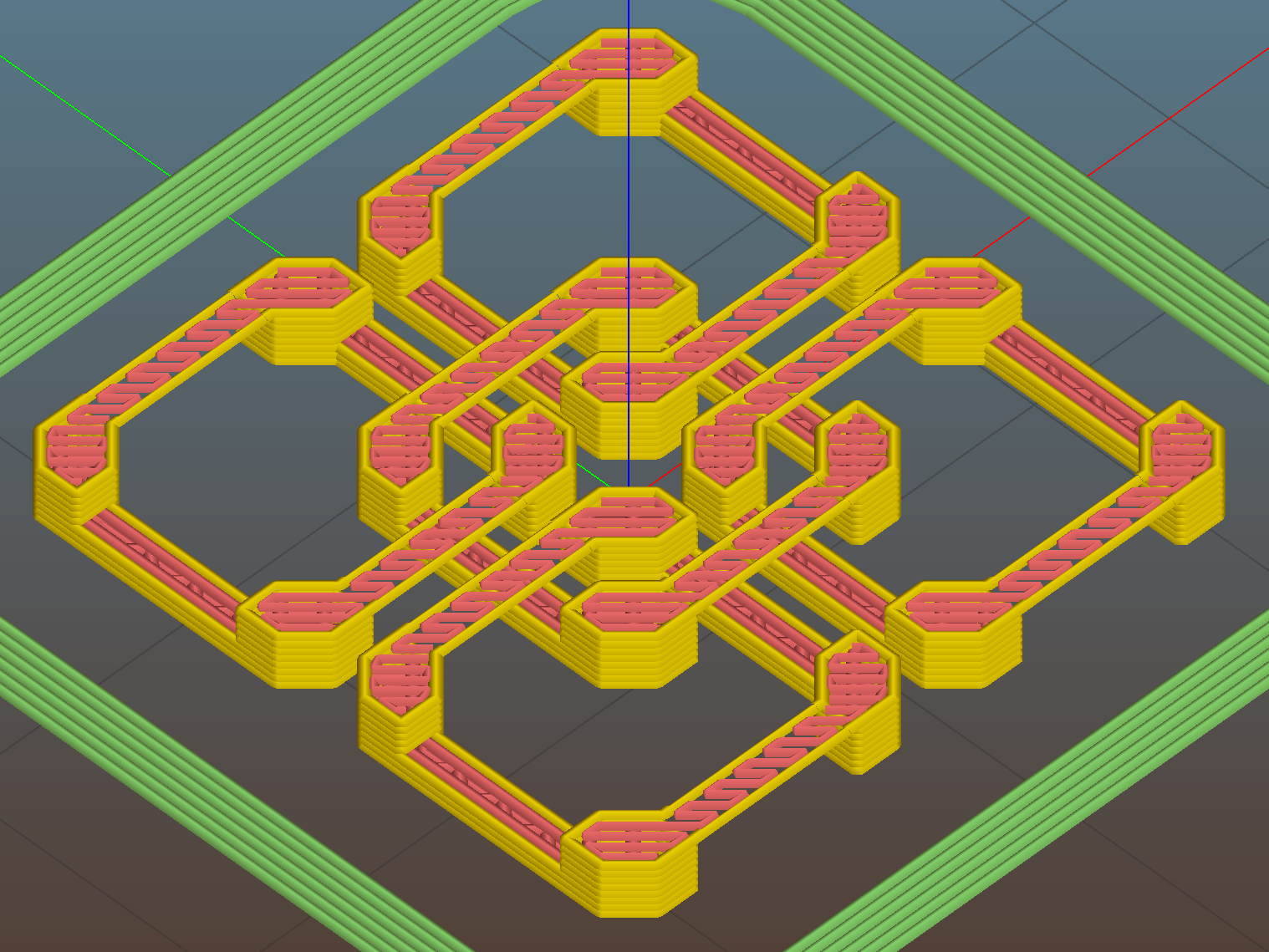
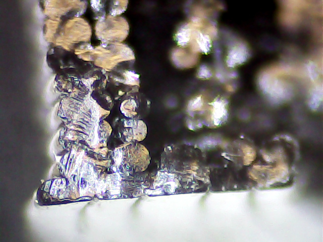
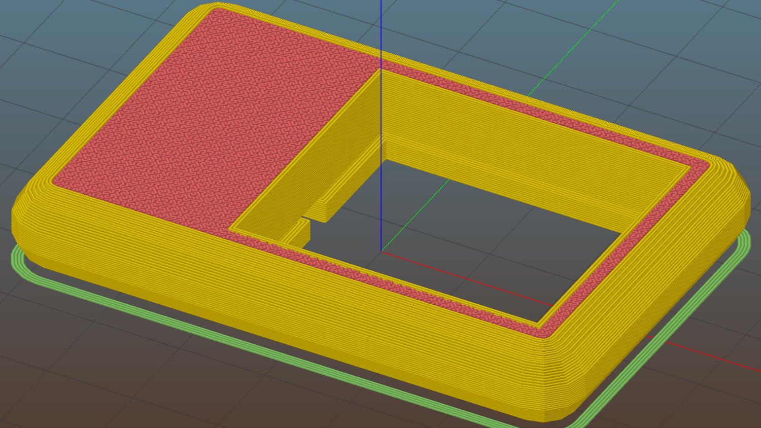
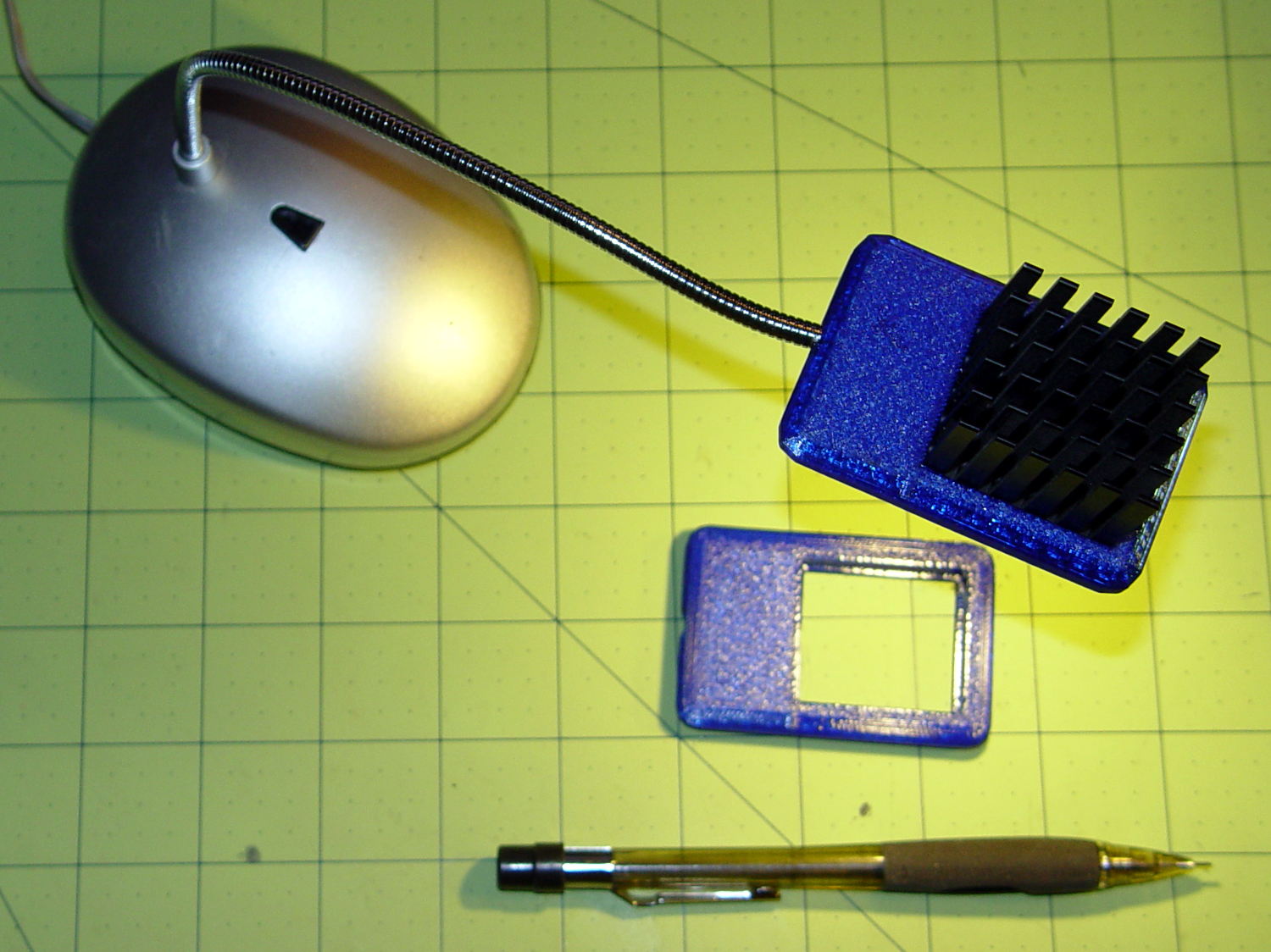
    This model is much more intricate than the stock washer:

    Olfa Rotary Cutter - backing washer
    Olfa Rotary Cutter – backing washer

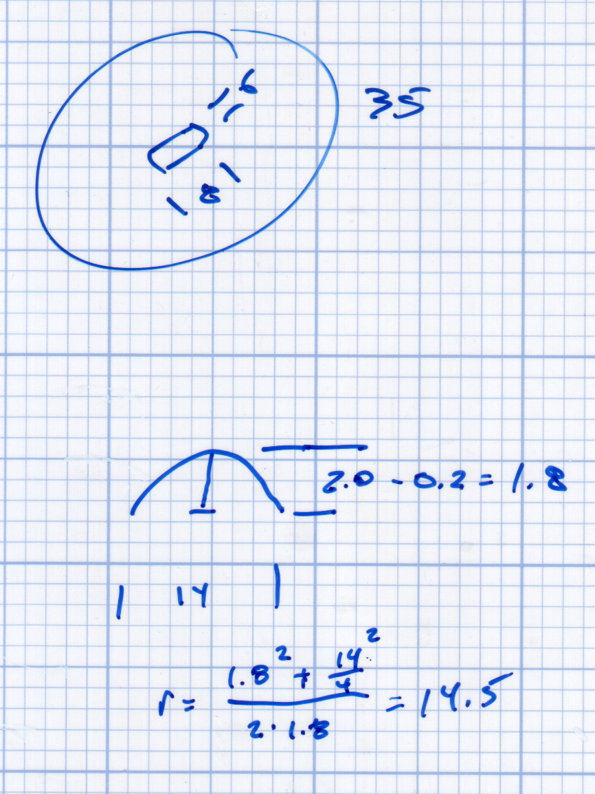
    The trench across the middle of the thicker part allows a wider compression adjustment range for the wave washer and provides more thread engagement at the lightest setting for my liking. The shape comes from the chord equation based on measurements of the wave washer:

    Olfa Rotary Cutter - washer doodles
    Olfa Rotary Cutter – washer doodles

    The wave washer keys on the bolt flats: the whole affair rotates with the blade and gives the nut no inclination to unscrew. If you remove the trench, the remaining hole has the proper shape to key on the bolt and rotate with it; with the trench in place, the wave washer’s sides haul the plastic washer along with it.

    The plain ring, just two threads thick, glues bottom-to-bottom on the thicker part to soak up the air gap and provide more blade stability. It’s not entirely clear that’s a win; it’s easy to omit.

    It looks about like you’d expect:

    Olfa Rotary Cutter - washer in place
    Olfa Rotary Cutter – washer in place

    The wave washer must go on the bolt with the smooth curve downward into the trench. That orientation that wasn’t enforced by the Official Olfa spacer washer’s smooth sides.

    The nut sits upside-down to show the face that normally sits against the wave washer. I’d lay long odds that the recess around the threads originally held a conical compression spring with a penchant for joining the dust bunnies under the sewing table. You can insert the wave washer the wrong way, but it doesn’t store enough energy to go airborne unless you drop it, which did happen once with the expected result.

    The OpenSCAD source code as a GitHub gist:

    // Olfa rotary cutter backing washer
    // Ed Nisley KE4ZNU January 2016
    Layout = "Build";
    //- Extrusion parameters must match reality!
    // Print with +1 shells and 3 solid layers
    ThreadThick = 0.20;
    ThreadWidth = 0.40;
    HoleWindage = 0.2;
    function IntegerMultiple(Size,Unit) = Unit * ceil(Size / Unit);
    Protrusion = 0.1; // make holes end cleanly
    //———————-
    // Dimensions
    WasherOD = 35.0;
    WasherThick = 1.5;
    WaveOD = 14.0; // wave washer flat dia
    WaveM = 1.8; // height of wave washer bend
    BendRad = (pow(WaveM,2) + pow(WaveOD,2)/4) / (2*WaveM); // radius of wave washer bend
    echo(str("Wave washer bend radius: ",BendRad));
    SpacerID = WaveOD + 2.0;
    SpacerThick = 2*ThreadThick;
    NumSides = 12*4;
    $fn = NumSides;
    //———————-
    // Useful routines
    module PolyCyl(Dia,Height,ForceSides=0) { // based on nophead's polyholes
    Sides = (ForceSides != 0) ? ForceSides : (ceil(Dia) + 2);
    FixDia = Dia / cos(180/Sides);
    cylinder(r=(FixDia + HoleWindage)/2,
    h=Height,
    $fn=Sides);
    }
    //———————-
    // Parts
    module Upper() {
    difference() {
    cylinder(d1=WasherOD,d2=(WasherOD – 2.0),h=WasherThick);
    translate([0,0,-Protrusion])
    intersection() {
    PolyCyl(8.2,2.0,8);
    cube([(6.0 + HoleWindage),10,2*WasherThick],center=true);
    }
    translate([-(WaveOD + 1.0)/2,0,BendRad])
    rotate([0,90,0]) rotate(0*180/16)
    PolyCyl(BendRad*2,(WaveOD + 1),16);
    }
    }
    module Spacer() {
    difference() {
    cylinder(d=WasherOD,h=SpacerThick);
    translate([0,0,-Protrusion])
    cylinder(d=SpacerID,h=2*SpacerThick);
    }
    }
    //———————-
    // Build it!
    if (Layout == "Show") {
    translate([0,0,SpacerThick])
    color("Cyan")
    Upper();
    color("LightCyan")
    Spacer();
    }
    if (Layout == "Build") {
    translate([-0.6*WasherOD,0,0])
    Upper();
    translate([0.6*WasherOD,0,0])
    Spacer();
    }
  • Miniature Chain Mail: Handouts

    I ran off a few patches of miniature chain mail for holiday handouts to a few folks who’d appreciate them:

    Chain Mail Armor - 6x6 9.6 mm - top view
    Chain Mail Armor – 6×6 9.6 mm – top view

    A little patch like that makes a fondletoy that’s easier to pocket than, say, a planetary gear bearing and should be robust enough to withstand quite a bit of abuse.

    Alas, it turned out that recent Slic3r development versions suffered a bridging regression. The stable 1.2.9 version does the right thing:

    Slic3r 1.2.9 - good bridging
    Slic3r 1.2.9 – good bridging

    The hot-from-Github version goes diagonally, producing a pattern like an internal layer that normally sits atop the (omitted) bridge layer:

    Slic3r 7c8b710 - diagonal bridging
    Slic3r 7c8b710 – diagonal bridging

    While that might barely work, the little bitty link bars will certainly fall into the abyss:

    Slic3r 7c8b710 - diagonal bridging on links
    Slic3r 7c8b710 – diagonal bridging on links

    Given the complexity of slicing algorithms, I definitely can’t track down the problem; using the stable version for a while should suffice.

    The OpenSCAD source code as a GitHub gist:

    // Chain Mail Armor Buttons
    // Ed Nisley KE4ZNU – December 2014
    Layout = "Build"; // Link Button LB Joiner Joiners Build PillarMod
    //——-
    //- Extrusion parameters must match reality!
    // Print with 1 shell and 2+2 solid layers
    ThreadThick = 0.25;
    ThreadWidth = 0.40;
    HoleWindage = 0.2;
    Protrusion = 0.1; // make holes end cleanly
    function IntegerMultiple(Size,Unit) = Unit * ceil(Size / Unit);
    //——-
    // Dimensions
    //- Set maximum sheet size
    SheetSizeX = 125; // 170 for full sheet on M2
    SheetSizeY = 125; // 230 …
    //- Diamond or rectangular sheet?
    Diamond = false; // true = rotate 45 degrees, false = 0 degrees for square
    BendAround = "X"; // X or Y = maximum flexibility *around* designated axis
    Cap = true; // true = build bridge layers over links
    CapThick = 4 * ThreadThick; // flat cap on link: >= 3 layers for solid bridging
    Armor = true && Cap; // true = build armor button atop (required) cap
    ArmorThick = IntegerMultiple(2.0,ThreadThick); // height above cap surface
    ArmorSides = 4;
    ArmorAngle = true ? 180/ArmorSides : 0; // true -> rotate half a side for best alignment
    //- Link bar sizes
    BarThick = 3 * ThreadThick;
    BarWidth = 3.3 * ThreadWidth;
    BarClearance = 3 * ThreadThick; // vertical clearance above & below bars
    VertexHack = false; // true to slightly reduce openings to avoid coincident vertices
    //- Compute link sizes from those values
    //- Absolute minimum base link: bar width + corner angle + build clearance around bars
    // rounded up to multiple of thread width to ensure clean filling
    BaseSide = IntegerMultiple((4*BarWidth + 2*BarWidth/sqrt(2) + 3*(2*ThreadWidth)),ThreadWidth);
    BaseHeight = 2*BarThick + BarClearance; // both bars + clearance
    echo(str("BaseSide: ",BaseSide," BaseHeight: ",BaseHeight));
    //echo(str(" Base elements: ",4*BarWidth,", ",2*BarWidth/sqrt(2),", ",3*(2*ThreadWidth)));
    //echo(str(" total: ",(4*BarWidth + 2*BarWidth/sqrt(2) + 3*(2*ThreadWidth))));
    BaseOutDiagonal = BaseSide*sqrt(2) – BarWidth;
    BaseInDiagonal = BaseSide*sqrt(2) – 2*(BarWidth/2 + BarWidth*sqrt(2));
    echo(str("Outside diagonal: ",BaseOutDiagonal));
    //- On-center distance measured along coordinate axis
    // the links are interlaced, so this is half of what you think it should be…
    LinkOC = BaseSide/2 + ThreadWidth;
    LinkSpacing = Diamond ? (sqrt(2)*LinkOC) : LinkOC;
    echo(str("Base spacing: ",LinkSpacing));
    //- Compute how many links fit in sheet
    MinLinksX = ceil((SheetSizeX – (Diamond ? BaseOutDiagonal : BaseSide)) / LinkSpacing);
    MinLinksY = ceil((SheetSizeY – (Diamond ? BaseOutDiagonal : BaseSide)) / LinkSpacing);
    echo(str("MinLinks X: ",MinLinksX," Y: ",MinLinksY));
    NumLinksX = ((0 == (MinLinksX % 2)) && !Diamond) ? MinLinksX + 1 : MinLinksX;
    NumLinksY = ((0 == (MinLinksY % 2) && !Diamond)) ? MinLinksY + 1 : MinLinksY;
    echo(str("Links X: ",NumLinksX," Y: ",NumLinksY));
    //- Armor button base
    ButtonHeight = BaseHeight + BarClearance + CapThick;
    echo(str("ButtonHeight: ",ButtonHeight));
    //- Armor ornament size & shape
    // Fine-tune OD & ID to suit the number of sides…
    TotalHeight = ButtonHeight + ArmorThick;
    echo(str("Overall Armor Height: ",TotalHeight));
    ArmorOD = 1.0 * BaseSide; // tune for best base fit
    ArmorID = 10 * ThreadWidth; // make the tip blunt & strong
    //——-
    module ShowPegGrid(Space = 10.0,Size = 1.0) {
    RangeX = floor(95 / Space);
    RangeY = floor(125 / Space);
    for (x=[-RangeX:RangeX])
    for (y=[-RangeY:RangeY])
    translate([x*Space,y*Space,Size/2])
    %cube(Size,center=true);
    }
    //——-
    // Create link with armor button as needed
    module Link(Topping = false) {
    LinkHeight = (Topping && Cap) ? ButtonHeight : BaseHeight;
    render(convexity=3)
    rotate((BendAround == "X") ? 90 : 0)
    rotate(Diamond ? 45 : 0)
    union() {
    difference() {
    translate([0,0,LinkHeight/2]) // outside shape
    intersection() {
    cube([BaseSide,BaseSide,LinkHeight],center=true);
    rotate(45)
    cube([BaseOutDiagonal,BaseOutDiagonal,(LinkHeight + 2*Protrusion)],center=true);
    }
    translate([0,0,(BaseHeight + BarClearance + 0*ThreadThick – Protrusion)/2])
    intersection() { // inside shape
    cube([(BaseSide – 2*BarWidth),
    (BaseSide – 2*BarWidth),
    (BaseHeight + BarClearance + 0*ThreadThick + (VertexHack ? Protrusion/2 : 0))],
    center=true);
    rotate(45)
    cube([BaseInDiagonal,
    BaseInDiagonal,
    (BaseHeight + BarClearance + 0*ThreadThick + (VertexHack ? Protrusion/2 : 0))],
    center=true);
    }
    translate([0,0,((BarThick + 2*BarClearance)/2 + BarThick)]) // openings for bars
    cube([(BaseSide – 2*BarWidth – 2*BarWidth/sqrt(2) – (VertexHack ? Protrusion/2 : 0)),
    (2*BaseSide),
    BarThick + 2*BarClearance – Protrusion],
    center=true);
    translate([0,0,(BaseHeight/2 – BarThick)])
    cube([(2*BaseSide),
    (BaseSide – 2*BarWidth – 2*BarWidth/sqrt(2) – (VertexHack ? Protrusion/2 : 0)),
    BaseHeight],
    center=true);
    }
    if (Topping && Armor)
    translate([0,0,(ButtonHeight – Protrusion)]) // sink slightly into the cap
    rotate(ArmorAngle)
    cylinder(d1=ArmorOD,d2=ArmorID,h=(ArmorThick + Protrusion), $fn=ArmorSides);
    }
    }
    //——-
    // Create split buttons to join sheets
    module Joiner() {
    translate([-LinkSpacing,0,0])
    difference() {
    Link(false);
    translate([0,0,BarThick + BarClearance + TotalHeight/2 – Protrusion])
    cube([2*LinkSpacing,2*LinkSpacing,TotalHeight],center=true);
    }
    translate([LinkSpacing,0,0])
    intersection() {
    translate([0,0,-(BarThick + BarClearance)])
    Link(true);
    translate([0,0,TotalHeight/2])
    cube([2*LinkSpacing,2*LinkSpacing,TotalHeight],center=true);
    }
    }
    //——-
    // Build it!
    //ShowPegGrid();
    if (Layout == "Link") {
    Link(false);
    }
    if (Layout == "Button") {
    Link(true);
    }
    if (Layout == "LB") {
    color("Brown") Link(true);
    translate([LinkSpacing,LinkSpacing,0])
    color("Orange") Link(false);
    }
    if (Layout == "Build")
    for (ix = [0:(NumLinksX – 1)],
    iy = [0:(NumLinksY – 1)]) {
    x = (ix – (NumLinksX – 1)/2)*LinkSpacing;
    y = (iy – (NumLinksY – 1)/2)*LinkSpacing;
    translate([x,y,0])
    color([(ix/(NumLinksX – 1)),(iy/(NumLinksY – 1)),1.0])
    if (Diamond)
    Link((ix + iy) % 2); // armor at odd,odd & even,even points
    else
    if ((iy % 2) && (ix % 2)) // armor at odd,odd points
    Link(true);
    else if (!(iy % 2) && !(ix % 2)) // connectors at even,even points
    Link(false);
    }
    if (Layout == "Joiner")
    Joiner();
    if (Layout == "Joiners") {
    NumJoiners = max(MinLinksX,MinLinksY)/2;
    for (iy = [0:(NumJoiners – 1)]) {
    y = (iy – (NumJoiners – 1)/2)*2*LinkSpacing + LinkSpacing/2;
    translate([0,y,0])
    color([0.5,(iy/(NumJoiners – 1)),1.0])
    Joiner();
    }
    }
    if (Layout == "PillarMod") // Slic3r modification volume to eliminate pillar infill
    translate([0,0,(BaseHeight + BarClearance)/2])
    cube([1.5*SheetSizeX,1.5*SheetSizeY,BaseHeight + BarClearance],center=true);
  • Sienna Hood Rod Pivot: Failure Analysis

    Our Larval Engineer returned the remaining chunk of the failed PLA hood rod pivot from “her” Sienna minivan:

    Sienna hood rod pivot - PLA fracture
    Sienna hood rod pivot – PLA fracture

    A closer look at the top surface (facing you in the picture above) shows the threads didn’t fuse into a solid mass across the entire object:

    Sienna Hood Pivot - PLA fracture - top
    Sienna Hood Pivot – PLA fracture – top

    The darker region in the middle comes from the infill pattern, which should have air gaps.

    The bottom surface (on the platform during printing) shows how the threads spread out when the nozzle is closer to the platform than the layer thickness:

    Sienna Hood Pivot - PLA fracture - bottom right
    Sienna Hood Pivot – PLA fracture – bottom right

    That’s more pronounced on the other side of the pivot:

    Sienna Hood Pivot - PLA fracture - bottom left 1
    Sienna Hood Pivot – PLA fracture – bottom left 1

    The infill looks like a separate wall inside the two perimeter threads. That’s pretty much what you get in the space between two close-set walls: there’s not enough room for the full infill pattern.

    A slightly different focus plane shows the mashed bottom layer, infill sitting atop the bottom layer, and fused perimeter threads:

    Sienna Hood Pivot - PLA fracture - bottom left 2
    Sienna Hood Pivot – PLA fracture – bottom left 2

    Because 3D printing doesn’t (and really can’t) produce a solid block of plastic, the object will fail much more readily than an injection-molded part. The threads in the most highly stressed section fail first, after which the remainder will just rip apart. In this case, the hood rod provides a huge lever that easily overstresses the plastic; I’m surprised the original part lasted as long as it did.

    We all knew PLA wasn’t the right material for the job, right from the start, so we’ll see how the enlarged PETG version works in the field.

  • Lenovo Q150: Opening the Case For an SSD

    A pre-Christmas sale brought a cheap SSD that rendered my oath not to install one in the Lenovo Q150 inoperative, so I had to figure out how to open the case. Removing the visible screws didn’t release the cover, but some exploratory prying eventually popped the internal snap latches. Knowing the latch & screw locations will simplify harvesting the SSD when that time comes…

    Front (with USB & SPDIF jacks):

    Lenovo Q150 - case latches - front
    Lenovo Q150 – case latches – front

    Rear (with all the other jacks):

    Lenovo Q150 - case screws - rear
    Lenovo Q150 – case screws – rear

    Top (with the heatsink outlet):

    Lenovo Q150 - case latches - top
    Lenovo Q150 – case latches – top

    Bottom (with the mounting boss):

    Lenovo Q150 - case latch screws - bottom
    Lenovo Q150 – case latch screws – bottom

    With the cover off, the inside looks like this:

    Lenovo Q150 - interior overview
    Lenovo Q150 – interior overview

    The two rubber blocks glued to the hard drive bracket (carrier / sled / whatever) conceal the screws holding that side to the chassis. However, removing the blocks and the screws didn’t release the bracket, because it had what looked like a black adhesive layer below the screw flanges:

    Lenovo Q150 - hidden drive bracket screw
    Lenovo Q150 – hidden drive bracket screw

    Gentle prying from the edge of the bracket eventually released it, showing that the black plastic was just an insulating layer. Below that, two thin foam strips had firmly affixed themselves to the PCB, despite not having any adhesive on that side:

    Lenovo Q150 - drive bracket - foam strips
    Lenovo Q150 – drive bracket – foam strips

    With the bracket on the bench, installing the SSD went exactly as you’d expect and reinstalling the cover was, quite literally, a snap.

  • Chip-on-board LED Desk Lamp Retrofit

    After the 5 mm white LEDs failed on the original desk lamp rebuild, I picked up some chip-on-board LED lamps from the usual eBay supplier:

    COB LED Desk Lamp - bottom
    COB LED Desk Lamp – bottom

    The LED’s aluminum baseplate (perhaps there’s an actual “board” inside the yellow silicone fill) is firmly epoxied to a small heatsink from the Big Box o’ Heatsinks, chosen on the basis of being the right size and not being too battered.

    The rather limited specs say the LED supply voltage can range from 9 to 12 V, suggesting a bit of slack, with a maximum dissipation of 3 W, which definitely requires a heatsink.

    The First Light test looked promising:

     COB LED Desk Lamp - first light
    COB LED Desk Lamp – first light

    That’s driven from the same 12 VDC 200 mA wall wart that I used for the failed ring light version. Measuring the results shows that the supply now runs at the ragged edge of its current rating, with the output voltage around 10.5 V with plenty of ripple:

    COB LED V I 100ma div
    COB LED V I 100ma div

    The 260 mA current (bottom, trace 1 at 100 mA/div) varies from 200 to 300 mA as the voltage (top, trace 2 at 2 V/div) varies between 10 V and a bit under 11 V. If you believe the RMS values, it’s dissipating 2.7 W and the heatsink runs at a pleasant 105 °F in an ordinary room. The wall wart gets about as warm as you’d expect; it contains an old heavy-iron transformer and rectifier, not a trendy switcher.

    The heatsink mount looks nice, in a geeky way:

    COB LED Desk Lamp - side detail
    COB LED Desk Lamp – side detail

    The left side must be that long to anchor the gooseneck; I thought about tapering the slab a bit, but, really, it’s OK the way it is. Dabs of epoxy hold the gooseneck and heatsink in place.

    The heatsink rests on a small ledge at the bottom of the slab that’s as tall as the COB LED is thick, with a wire channel from the gooseneck socket:

    COB LED Heatsink mount - Slic3r
    COB LED Heatsink mount – Slic3r

    The Hilbert Curve infill on the top produces a textured finish; I’m a sucker for that pattern.

    The old lamp base isn’t particularly stylin’, but the new head lights up my desk below the big monitors without any glare:

    COB LED Desk Lamp - overview
    COB LED Desk Lamp – overview

    Now, let’s see how long this one lasts…

    The OpenSCAD source code as a Github gist:

    // Chip-on-board LED light heatsink mount for desk lamp
    // Ed Nisley KE4ZNU December 2015
    Layout = "Show"; // Show Build
    //- Extrusion parameters must match reality!
    ThreadThick = 0.25;
    ThreadWidth = 0.40;
    HoleWindage = 0.2;
    Protrusion = 0.1; // make holes end cleanly
    inch = 25.4;
    function IntegerMultiple(Size,Unit) = Unit * ceil(Size / Unit);
    //———————-
    // Dimensions
    ID = 0; // for round things
    OD = 1;
    LENGTH = 2;
    Gooseneck = [3.0,5.0,15.0]; // anchor for end of gooseneck
    COB = [25.0,23.0,2.5]; // Chip-on-board LED module
    Heatsink = [35.5,31.5,4.0]; // height is solid base bottom
    HSWire = [23.0,28.0,53.3]; // anchor width OC, width OAL, length OC
    HSWireDia = 1.4;
    HSLip = 1.0; // width of lip under heatsink
    BaseMargin = 2*2*ThreadWidth;
    BaseRadius = Gooseneck[OD]; // 2 x gooseneck = enough anchor, sets slab thickness
    BaseSides = 2*4;
    Base = [(Gooseneck[LENGTH] + Gooseneck[OD] + Heatsink[0] + 2*BaseRadius + BaseMargin),
    (Heatsink[1] + 2*BaseRadius + 2*BaseMargin),
    2*BaseRadius];
    //———————-
    // Useful routines
    module PolyCyl(Dia,Height,ForceSides=0) { // based on nophead's polyholes
    Sides = (ForceSides != 0) ? ForceSides : (ceil(Dia) + 2);
    FixDia = Dia / cos(180/Sides);
    cylinder(r=(FixDia + HoleWindage)/2,
    h=Height,
    $fn=Sides);
    }
    //– Lamp heatsink mount
    module Lamp() {
    difference() {
    translate([(Base[0]/2 – BaseRadius – Gooseneck[LENGTH]),0,0])
    hull()
    for (i=[-1,1], j=[-1,1])
    translate([i*(Base[0]/2 – BaseRadius),j*(Base[1]/2 – BaseRadius),Base[2]/2])
    sphere(r=BaseRadius/cos(180/BaseSides),$fn=BaseSides);
    translate([(Heatsink[0]/2 + Gooseneck[OD]),0,Heatsink[2] + COB[2]]) // main heatsink recess
    scale([1,1,2])
    cube((Heatsink + [HoleWindage,HoleWindage,0.0]),center=true);
    translate([(Heatsink[0]/2 + Gooseneck[OD]),0,Heatsink[2] – Protrusion]) // lower lip to shade lamp module
    scale([1,1,2])
    cube(Heatsink – [2*HSLip,2*HSLip,0],center=true);
    translate([0,0,Base[2]/2]) // goooseneck insertion
    rotate([0,-90,0]) rotate(180/8)
    PolyCyl(Gooseneck[OD],Base[0],8);
    translate([0,0,Base[2]/2 + Gooseneck[ID]/2]) // wire exit
    rotate([180,0,0])
    PolyCyl(Gooseneck[ID],Base[2],6);
    translate([Gooseneck[OD],0,(COB[2] – Protrusion)/2]) // wire slot
    rotate([180,0,0])
    cube([2*Gooseneck[OD],Gooseneck[ID],(COB[2] + Protrusion)],center=true);
    }
    }
    //———————-
    // Build it
    if (Layout == "Show") {
    Lamp();
    }
    if (Layout == "Build") {
    }
  • Tools for Ladies

    Wandering through the Sears tool department, I found this corner:

    Sears Pink Box Tools
    Sears Pink Box Tools

    Neither of the Ladies in my life favor pink, so I wasn’t even tempted…

    Mary wonders if the designers scaled the grips and spring tensions to suit women’s hands. Her experience shows that “tools for men” are too big and require too much grip strength for her comfort; applying pink plastic won’t improve them in the least.

  • Kenmore Progressive Vacuum Cleaner: Improved Suction Control

    The Suction Control slider on the handle of our shiny new Kenmore Progressive vacuum cleaner varies the speed of the howling motor in the base unit, rather than venting more or less air into the pipe. We like that, but it’s all too easy to inadvertently slide the control and never notice it, sooo I marked the default condition:

    Kenmore Progressive Vacuum - visible suction slider
    Kenmore Progressive Vacuum – visible suction slider

    Although every vacuum cleaner we’ve ever owned has touted its “quiet operation”, we always wear 30 dB ear muffs and it’s sometimes hard to tell the difference between full throttle and not quite so fast…