Ed Nisley's Blog: Shop notes, electronics, firmware, machinery, 3D printing, laser cuttery, and curiosities. Contents: 100% human thinking, 0% AI slop.
Mary’s new half-gallon sprayer arrived with a kink in the hose just below the handle, which is about what you’d expect from a non-reinforced plastic tube jammed into the smallest possible box containing both the sprayer and its wand. Fortunately, the Box o’ Springs had one that just fit the hose and jammed firmly into the handle:
Sprayer hose with kink-resisting spring
The kink slowly worked its way out after being surrounded by the spring and shouldn’t come back.
The evacuation tip nearly touched the inside end of the base spigot!
I had to cut the shaft and half the body off the shell drill in order to fit it into the space above the tube base and below the chuck:
5U4GB – base shell drilling
A slightly larger shell drill would still fit within the pin circle, but the maximum possible hole diameter in the base really isn’t all that much larger:
5U4GB – base opening
The getter flash covers the entire top of this tube, so I conjured a side light for a rectangular knockoff Neopixel:
Vacuum Tube Lights – side light – solid model
There’s no orientation that doesn’t require support:
Vacuum Tube Lights – side light support – Slic3r preview
A little prying with a small screwdriver and some pulling with a needlenose pliers extracted those blobs. All the visible surfaces remained undamaged and I cleaned up the curved side with a big rat-tail file.
I wired the Arduino and Neopixels, masked a spot on the side of the tube (to improve both alignment and provide protection from slobbered epoxy), applied epoxy, and taped it in place until it cured:
5U4GB – sidelight epoxy curing
The end result looks great:
5U4GB Full-wave vacuum rectifier – side and base illumination
It currently sends Morse code through the base LED, but it’s much too stately for that.
It seems everybody must disassemble an American Standard kitchen faucet to replace the spout seal O-rings, as my description of How It’s Done has remained in the top five most popular posts since I wrote it up in 2009.
About two years ago, I replaced the valve cartridge with a (presumably) Genuine Replacement; unlike the O-rings, the original valve lasted for nigh onto a decade. A few weeks ago, the replacement valve began squeaking and dribbling: nothing lasts any more. Another (presumably) Genuine Replacement, this time from Amazon, seems visually identical to the previous one and we’ll see how long it lasts.
I always wondered what was inside those faucets and, after breaking off the latching tabs in the big housing to the upper right, now I know:
American Standard Faucet – disassembled
You get a bunch of stuff for twelve bucks! The stainless steel valve actuator is off to the right, still grabbed in the bench vise.
The valve action comes from those two intricate ceramic blocks with a watertight sliding fit:
American Standard Faucet – ceramic valve parts
In fact, you (well, I) can wring the slabs together, just like a pair of gauge blocks. That kind of ultra-smooth surface must be useful for some other purpose, even though I can’t imagine what it might be…
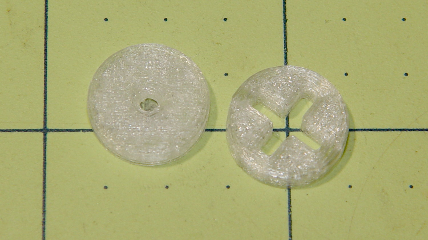
I made the pencil guides to help Mary design ruler quilting patterns, but sometimes she must line up the ruler with a feature on an existing pattern. To that end, we now have a reticle guide:
Ruler Adapters – pencil guide and reticle
The general idea is that it’s easier to see the pattern on paper through the crosshair than through a small hole. You put the button over a feature, align the reticle, put the ruler against the button, replace it with pencil guide, and away you go.
The solid model looks much more lively than you’d expect:
Ruler Adapter – reticle – Slic3r preview
Printing up a pair of each button produces the same surface finish as before; life is good!
This file contains hidden or bidirectional Unicode text that may be interpreted or compiled differently than what appears below. To review, open the file in an editor that reveals hidden Unicode characters.
Learn more about bidirectional Unicode characters
When I installed the new fine-tooth filament drive gear (wheel, whatever) in the M2, I ran some numbers that suggested replacing the fixed-position screw with a (more-or-less-)constant-force spring. Some recent discussions on the M2 forum suggest, at least to me, that the drive gear is, indeed, less forgiving of filament diameter variations, drive housing wear, and suchlike than the chunkier old gear.
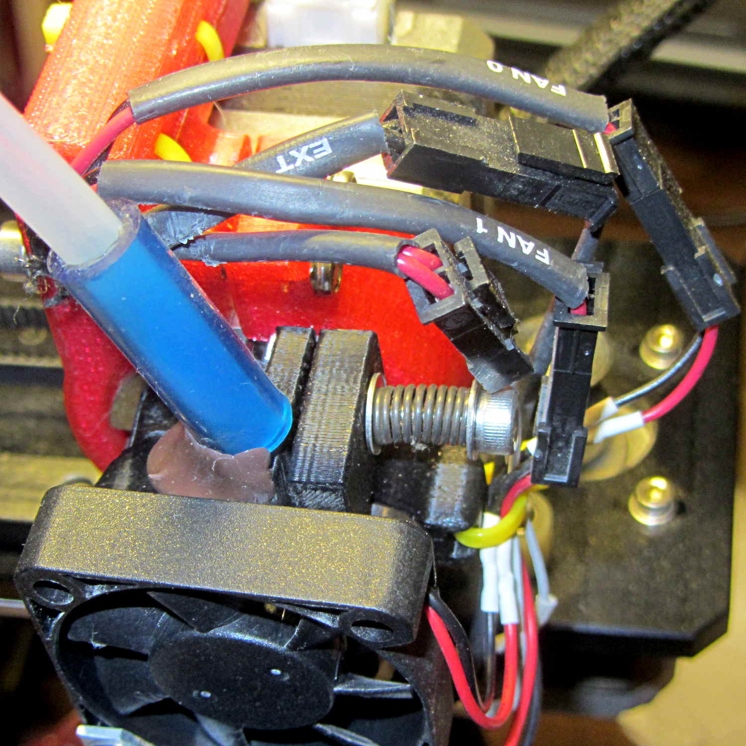
Having recently bought an assortment of longer M4 screws, I finally got around to installing an appropriate spring from the Big Box o’ Springs and another washer to capture it:
Makergear M2 – spring-loaded filament drive
Before doing anything, I measured the gap between the filament drive body (on the left) and the lever arm (on the right) holding the idler bearing: 21 mil = 0.53 mm.
I don’t have a number for the spring constant; it’s rather stiff.
After installing the spring, I cranked the screw to restore the same gap as before, which should mean the spring is exerting roughly the same force on the arm as the fixed-position screw.
The general idea: the spring allows the flexible arm to move as the filament diameter changes, while maintaining roughly the same pressure on the drive gear, thus producing nearly the same depth-of-engagement grooves in the filament. Maintaining “the same pressure” requires the motion to be relatively small compared to the spring preload distance, which seems reasonable with ±0.1 mm diameter variations and maybe 5 mm of preload.
The new filament drive gear hasn’t ever stripped out (after that initial finger fumble), so this will be more of a test to verify that the spring doesn’t make the situation worse.
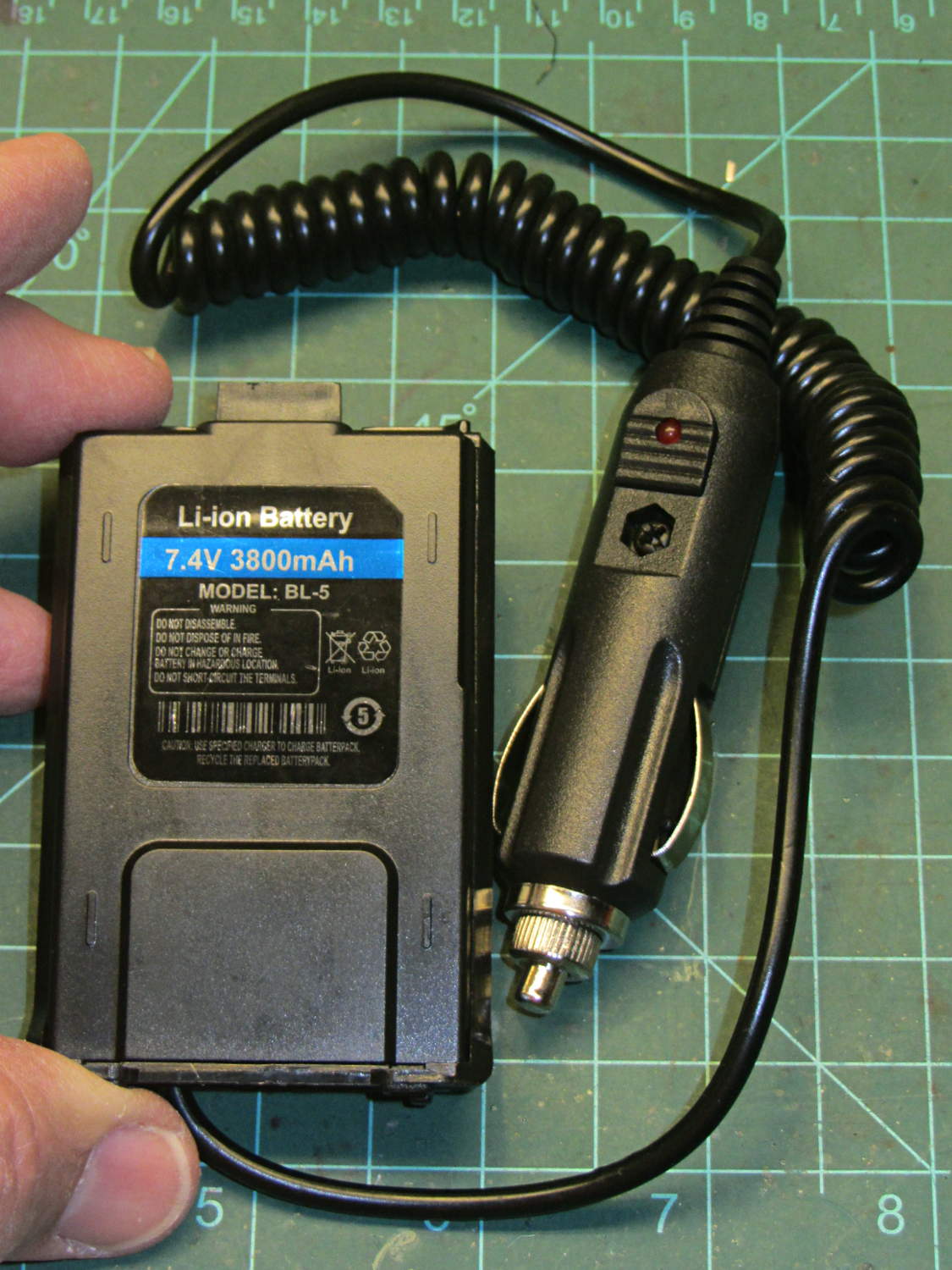
The OEM battery, tucked inside a case that’s for all intents and purposes identical to this one, sports an 1800 mA·h rating that I regarded as mmmm optimistic; I’d expect maybe 1000 mA·h, tops. From what I can tell, the 3800 mA·h label should go on an extended-capacity “big” battery that wraps around the bottom of the radio. Maybe the factory produced a pallet of mis-labeled small packs that they couldn’t fob off on actual customers with a straight face and couldn’t justify the labor to peel-and-stick the proper labels.
Anyhow, it’s not a battery.
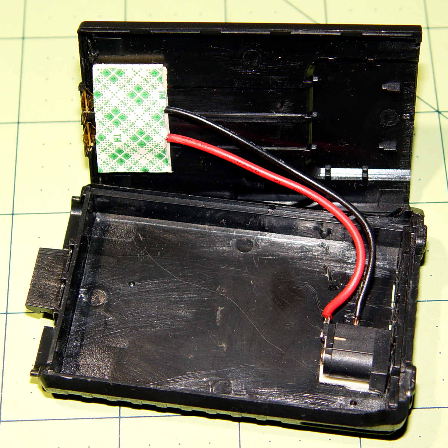
The circuitry inside shows considerably more fit & finish than I expected:
Baofeng Battery Eliminator – interior
It’s not clear how effective that heatsink could be, given that it’s trapped inside a compact plastic enclosure snugged against the radio’s metal chassis, but it’s a nice touch. Two layers of foam tape anchor the terminals at the top and hold the heatsink / LM7808-class TO-220 regulator in place.
Although I wanted the DC input to come from the side, rather than the bottom, so the radio could stand up, the pack simply isn’t thick enough to accommodate the jack in that orientation. I drilled out the existing wire hole to fit a coaxial power plug and deployed my own foam tape:
Baofeng Battery Eliminator – rewired interior
Replacing the foam tape at the top holds the bent-brass (?) terminals in more-or-less the proper orientation, with Genuine 3M / Scotch Plaid adding a festive touch. A groove in the other half of the shell captures the free ends of those terminals, so they’re not flopping around in mid-air.
The jack fits an old-school 7.5 V transformer wall wart that produces 11 V open-circuit. It’s probably still a bit too high with the UV-5R’s minimal receive-only load, but I refuse to worry.
Now KE4ZNU-10 won’t become a lithium fire in the attic stairwell…
While I had the hood up, I used Chirp to gut the radio’s stored frequencies / channels / memories and set 144.39 in Memory 0 as the only non-zero value. With a bit of luck, that will prevent it from crashing and jamming a randomly chosen frequency outside the amateur bands…