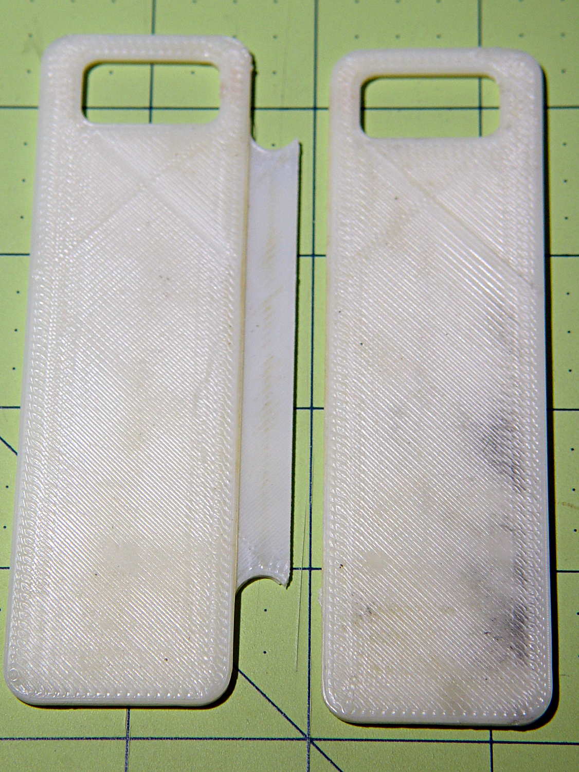
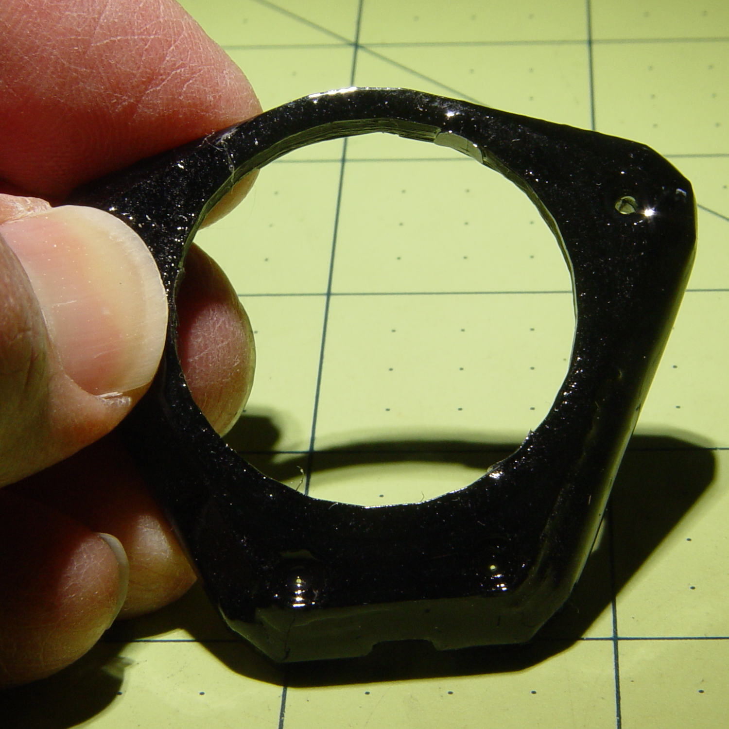
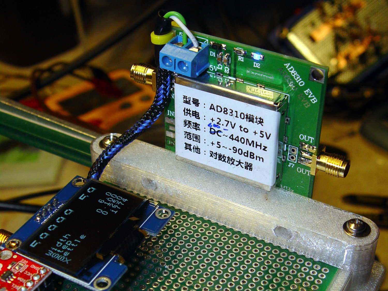
This little bracket attaches to a proto board holder, with holes for M3 inserts to mount the AD8310 log amp module:

Thusly:
The OLED display looks a bit faded, which seems to be an interaction between matrix refresh and camera shutter: looks just fine in person!
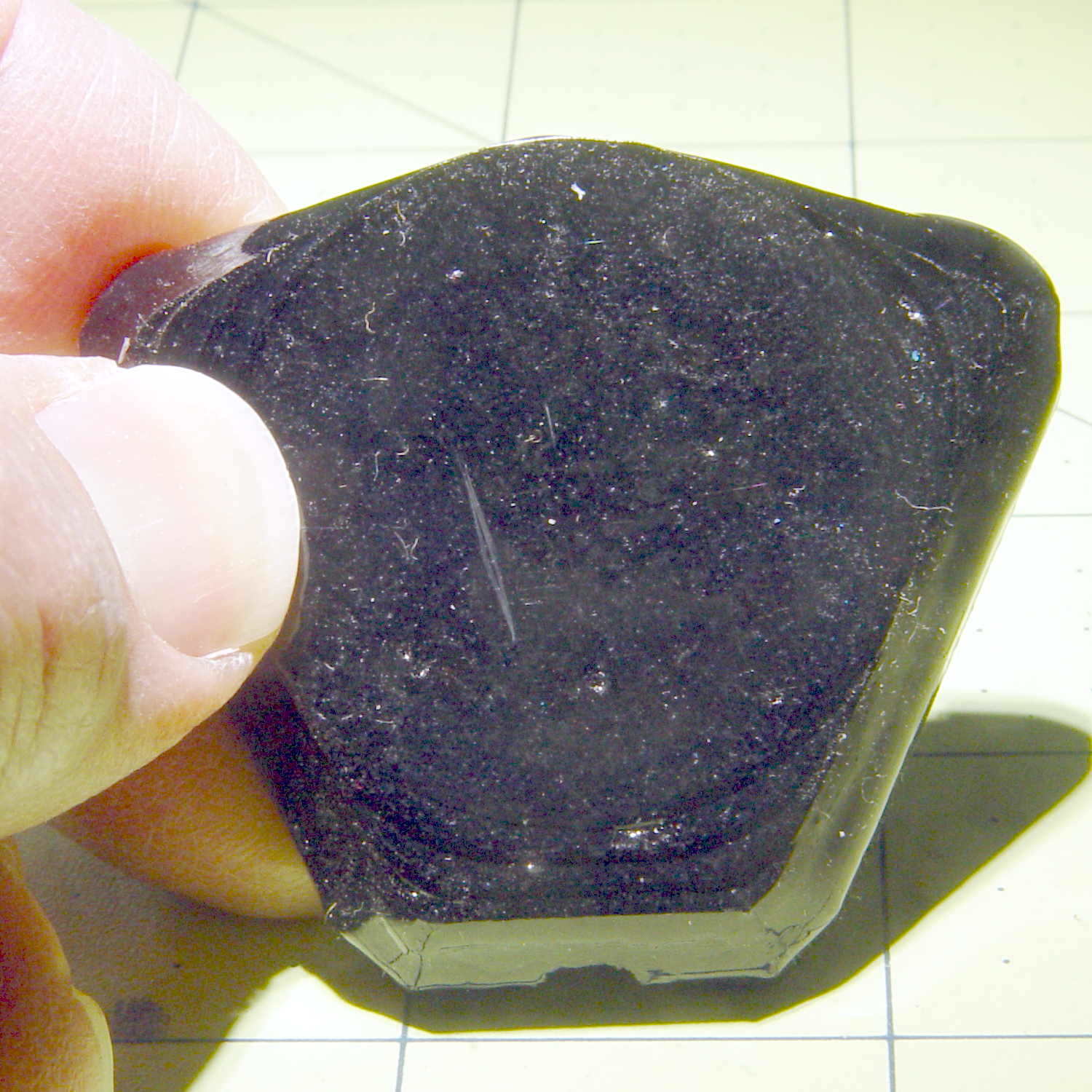
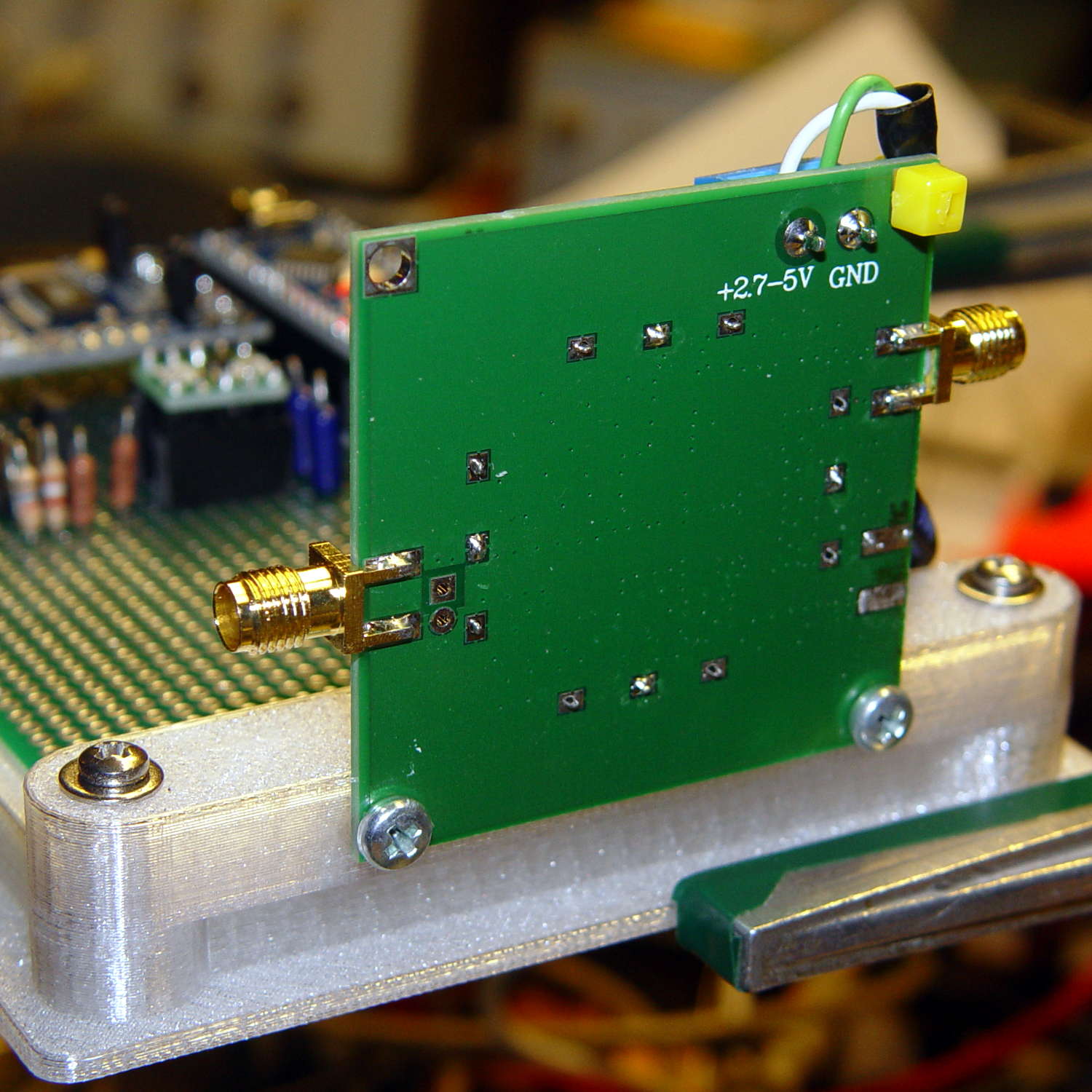
Not much to see from the other side:
I should have included an offset to slide it a bit forward; then I could mount it on the other end with clearance for the Nano’s USB port. Maybe next time.
The OpenSCAD source code as a GitHub Gist:
This file contains hidden or bidirectional Unicode text that may be interpreted or compiled differently than what appears below. To review, open the file in an editor that reveals hidden Unicode characters.
Learn more about bidirectional Unicode characters
| // Test support frame for proto boards | |
| // Ed Nisley KE4ZNU – Jan 2017 | |
| // June 2017 – Add side-mount bracket | |
| Layout = "Bracket"; | |
| ClampFlange = true; | |
| Channel = false; | |
| //- Extrusion parameters – must match reality! | |
| ThreadThick = 0.25; | |
| ThreadWidth = 0.40; | |
| function IntegerMultiple(Size,Unit) = Unit * ceil(Size / Unit); | |
| Protrusion = 0.1; | |
| HoleWindage = 0.2; | |
| //- Screw sizes | |
| inch = 25.4; | |
| Tap4_40 = 0.089 * inch; | |
| Clear4_40 = 0.110 * inch; | |
| Head4_40 = 0.211 * inch; | |
| Head4_40Thick = 0.065 * inch; | |
| Nut4_40Dia = 0.228 * inch; | |
| Nut4_40Thick = 0.086 * inch; | |
| Washer4_40OD = 0.270 * inch; | |
| Washer4_40ID = 0.123 * inch; | |
| ID = 0; | |
| OD = 1; | |
| LENGTH = 2; | |
| Insert = [3.9,4.6,5.8]; | |
| //- PCB sizes | |
| PCBSize = [80.0,120.0,1.6]; | |
| PCBShelf = 1.5; | |
| Clearance = 2*[ThreadWidth,ThreadWidth,0]; | |
| WallThick = 4.0; | |
| FrameHeight = 8.0; | |
| ScrewOffset = 0.0 + Clear4_40/2; | |
| ScrewSites = [[-1,1],[-1,1]]; // -1/0/+1 = left/mid/right and bottom/mid/top | |
| OAHeight = FrameHeight + Clearance[2] + PCBSize[2]; | |
| echo(str("OAH: ",OAHeight)); | |
| FlangeExtension = 3.0; | |
| FlangeThick = IntegerMultiple(2.0,ThreadThick); | |
| Flange = PCBSize | |
| + 2*[ScrewOffset,ScrewOffset,0] | |
| + 2*[Washer4_40OD,Washer4_40OD,0] | |
| + [2*FlangeExtension,2*FlangeExtension,(FlangeThick – PCBSize[2])] | |
| ; | |
| echo(str("Flange: ",Flange)); | |
| NumSides = 4*5; | |
| WireChannel = [Flange[0],15.0,3.0 + PCBSize[2]]; | |
| WireChannelOffset = [Flange[0]/2,25.0,(FrameHeight + PCBSize[2] – WireChannel[2]/2)]; | |
| //- Adjust hole diameter to make the size come out right | |
| module PolyCyl(Dia,Height,ForceSides=0) { // based on nophead's polyholes | |
| Sides = (ForceSides != 0) ? ForceSides : (ceil(Dia) + 2); | |
| FixDia = Dia / cos(180/Sides); | |
| cylinder(r=(FixDia + HoleWindage)/2,h=Height,$fn=Sides); | |
| } | |
| //- Build things | |
| if (Layout == "Frame") | |
| difference() { | |
| union() { // body block | |
| translate([0,0,OAHeight/2]) | |
| cube(PCBSize + Clearance + [2*WallThick,2*WallThick,FrameHeight],center=true); | |
| for (x=[-1,1], y=[-1,1]) { // screw bosses | |
| translate([x*(PCBSize[0]/2 + ScrewOffset), | |
| y*(PCBSize[1]/2 + ScrewOffset), | |
| 0]) | |
| cylinder(r=Washer4_40OD,h=OAHeight,$fn=NumSides); | |
| } | |
| if (ClampFlange) // flange for work holder | |
| linear_extrude(height=Flange[2]) | |
| hull() | |
| for (i=[-1,1], j=[-1,1]) { | |
| translate([i*(Flange[0]/2 – Washer4_40OD/2),j*(Flange[1]/2 – Washer4_40OD/2)]) | |
| circle(d=Washer4_40OD,$fn=NumSides); | |
| } | |
| } | |
| for (x=[-1,1], y=[-1,1]) { // screw position indexes | |
| translate([x*(PCBSize[0]/2 + ScrewOffset), | |
| y*(PCBSize[1]/2 + ScrewOffset), | |
| -Protrusion]) | |
| rotate(x*y*180/(2*6)) | |
| PolyCyl(Clear4_40,(OAHeight + 2*Protrusion),6); // screw clearance holes | |
| translate([x*(PCBSize[0]/2 + ScrewOffset), | |
| y*(PCBSize[1]/2 + ScrewOffset), | |
| OAHeight – PCBSize[2] – Insert[LENGTH]]) | |
| rotate(x*y*180/(2*6)) | |
| PolyCyl(Insert[OD],Insert[LENGTH] + Protrusion,6); // inserts | |
| translate([x*(PCBSize[0]/2 + ScrewOffset), | |
| y*(PCBSize[1]/2 + ScrewOffset), | |
| OAHeight – PCBSize[2]]) | |
| PolyCyl(1.2*Washer4_40OD,(PCBSize[2] + Protrusion),NumSides); // washers | |
| } | |
| translate([0,0,OAHeight/2]) // through hole below PCB | |
| cube(PCBSize – 2*[PCBShelf,PCBShelf,0] + [0,0,2*OAHeight],center=true); | |
| translate([0,0,(OAHeight – (PCBSize[2] + Clearance[2])/2 + Protrusion/2)]) // PCB pocket on top | |
| cube(PCBSize + Clearance + [0,0,Protrusion],center=true); | |
| if (Channel) | |
| translate(WireChannelOffset) // opening for wires from bottom side | |
| cube(WireChannel + [0,0,Protrusion],center=true); | |
| } | |
| // Add-on bracket to hold smaller PCB upright at edge | |
| PCB2Insert = [3.0,4.9,4.1]; | |
| PCB2OC = 45.0; | |
| if (Layout == "Bracket") | |
| difference() { | |
| hull() // frame body block | |
| for (x=[-1,1]) // bosses around screws | |
| translate([x*(PCBSize[0]/2 + ScrewOffset),0,0]) | |
| cylinder(r=Washer4_40OD,h=OAHeight,$fn=NumSides); | |
| for (x=[-1,1]) // frame screw holes | |
| translate([x*(PCBSize[0]/2 + ScrewOffset),0,-Protrusion]) | |
| rotate(x*180/(2*6)) | |
| PolyCyl(Clear4_40,(OAHeight + 2*Protrusion),6); | |
| for (x=[-1,1]) // PCB insert holes | |
| translate([x*PCB2OC/2,(Washer4_40OD + Protrusion),OAHeight/2]) | |
| rotate([90,0,0]) | |
| cylinder(d=PCB2Insert[OD],h=2*(Washer4_40OD + Protrusion),$fn=6); | |
| } | |