The Smell of Molten Projects in the Morning

Ed Nisley's Blog: Shop notes, electronics, firmware, machinery, 3D printing, laser cuttery, and curiosities. Contents: 100% human thinking, 0% AI slop.

Category: Machine Shop

Mechanical widgetry

  • RAMPS 1.4: Configuration for Generic Motor Control

    Configuring the knockoff RAMPS 1.4 board went reasonably smoothly:

    RAMPS 1.4 - First Light
    RAMPS 1.4 – First Light

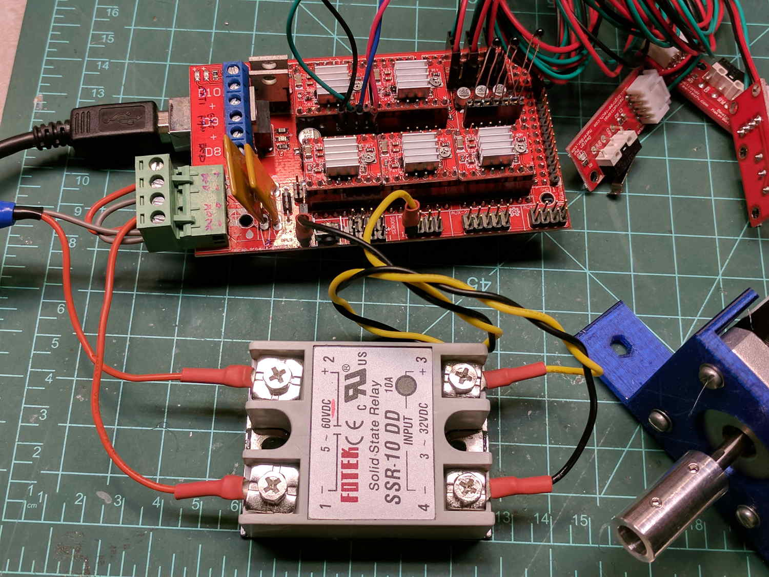
    The DC (n.b., not an AC) solid state relay in the foreground switches the 20 V laptop supply brick to the RAMPS shield atop the knockoff Arduino Mega 2560, controlled by the PS_ON pin (black wire), with +5 V from a pin in the AUX header (yellow wire). The SSR includes a ballast resistor limiting the current to 12 mA, with an inconspicuous red LED behind the black dot showing when the output is turned on.

    Because it’s a DC SSR, polarity matters: the supply goes to the + terminal, the RAMPS power inputs to the – terminal.

    I haven’t applied much of a load to to the SSR, but it works as expected. Define POWER_SUPPLY 1 and PS_DEFAULT_OFF so the boards starts up with the SSR turned off, then use M80 / M81 to turn it on / off as needed.

    Remove D1 on the RAMPS board to isolate the Mega power from the +20 V supply. Stuffed as shown, the Mega draws 70 mA from the USB port, although an external 8 V (-ish) supply is always a good idea.

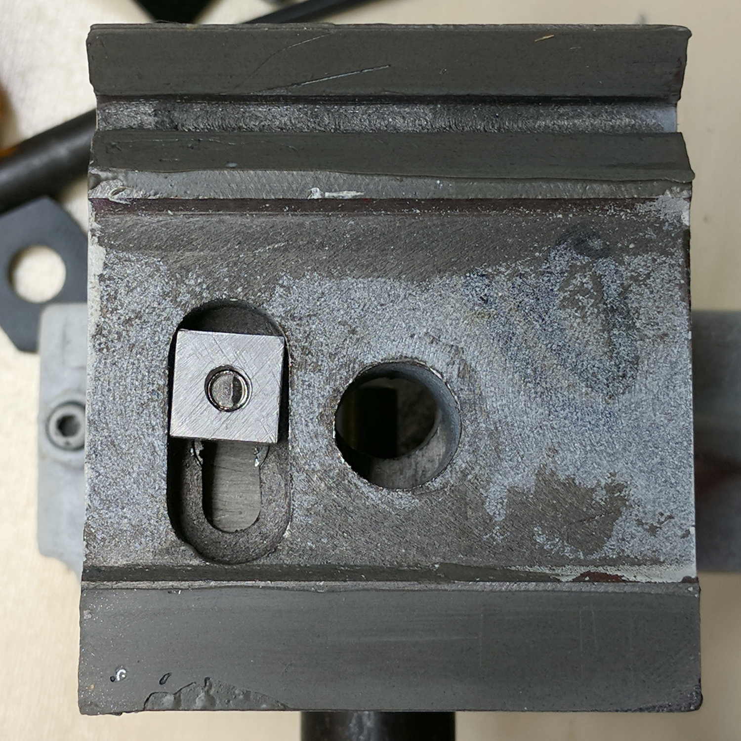
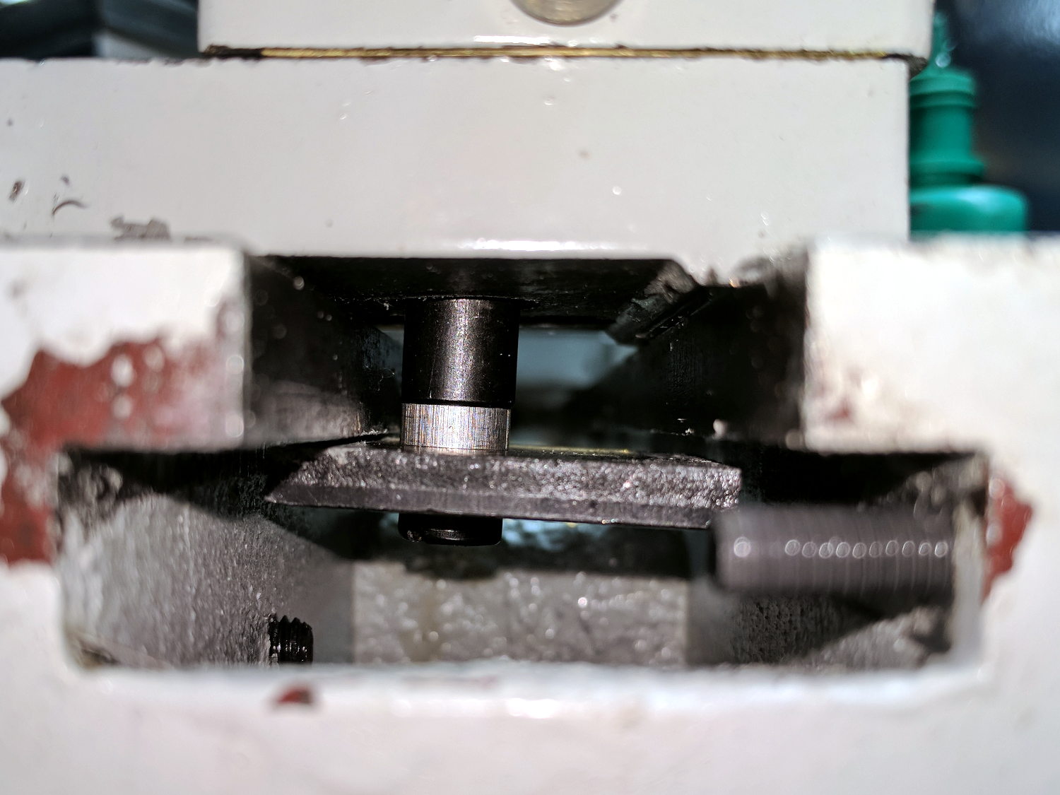
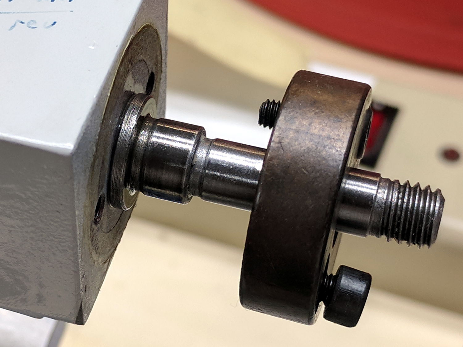
    The stepper is a random NEMA 17 from the heap in a mount intended for a DIY plotter. I adjusted the tiny trimpots on all the boards for 400 mA peak = 250 mA RMS into the windings, after finding 250 mApk didn’t produce nearly enough mojo, even for a demonstration:

    X Axis Stepper Drive
    X Axis Stepper Drive

    Just to get it running, I used DEFAULT_AXIS_STEPS_PER_UNIT = 100 step/mm, MAX_FEEDRATE 100 mm/s, and (for lack of anything better)
    DEFAULT_*_ACCELERATION 1000. Those all depend the torque produced by the motor current, which is still way too low.

    The endstops require X_???_ENDSTOP_INVERTING true.

    I set the ?_BED_SIZE parameters to a generous 2000, with ?_MIN_POS equal to -SIZE/2 to put the origin in the middle where I prefer it, with a similar setting for the Z axis. Obviously, those numbers don’t correspond to any physical reality.

    Three little 100 kΩ thermistors sprout from their header and produce reasonable temperatures, although (being cheap eBay parts) they may not match the Type 4 curve. I don’t have any heaters connected. All the over / under temperature lockouts are disabled, because I don’t care right now.

    The G-Code parser wants uppercase command letters, which means I get to press the Caps Lock key for the first time in nearly forever!

    The header along the right edge of the board connects to the LCD control board, which is another story.

    The diffs for the Configuration.h and Configuration_adv.h files as a GitHub Gist:

    77c77
    < #define STRING_CONFIG_H_AUTHOR "(none, default config)" // Who made the changes.
    > #define STRING_CONFIG_H_AUTHOR "(Ed Nisley – KE4ZNU)" // Who made the changes.
    113c113
    < #define BAUDRATE 250000
    > #define BAUDRATE 115200
    126c126
    < //#define CUSTOM_MACHINE_NAME "3D Printer"
    > #define CUSTOM_MACHINE_NAME "Not a 3D Printer"
    130c130
    < //#define MACHINE_UUID "00000000-0000-0000-0000-000000000000"
    > #define MACHINE_UUID "89647f7b-2575-4809-bc90-5396f4376e02"
    225c225
    < #define POWER_SUPPLY 0
    > #define POWER_SUPPLY 1
    230c230
    < //#define PS_DEFAULT_OFF
    > #define PS_DEFAULT_OFF
    285c285
    < #define TEMP_SENSOR_0 1
    > #define TEMP_SENSOR_0 4
    290c290
    < #define TEMP_SENSOR_BED 0
    > #define TEMP_SENSOR_BED 4
    304c304
    < #define TEMP_WINDOW 1 // (degC) Window around target to start the residency timer x degC early.
    > #define TEMP_WINDOW 2 // (degC) Window around target to start the residency timer x degC early.
    309c309
    < #define TEMP_BED_WINDOW 1 // (degC) Window around target to start the residency timer x degC early.
    > #define TEMP_BED_WINDOW 2 // (degC) Window around target to start the residency timer x degC early.
    324,325c324,325
    < #define HEATER_0_MAXTEMP 275
    < #define HEATER_1_MAXTEMP 275
    > #define HEATER_0_MAXTEMP 75
    > #define HEATER_1_MAXTEMP 75
    329c329
    < #define BED_MAXTEMP 150
    > #define BED_MAXTEMP 75
    417,418c417,418
    < #define PREVENT_COLD_EXTRUSION
    < #define EXTRUDE_MINTEMP 170
    > //#define PREVENT_COLD_EXTRUSION
    > #define EXTRUDE_MINTEMP 50
    422c422
    < #define PREVENT_LENGTHY_EXTRUDE
    > //#define PREVENT_LENGTHY_EXTRUDE
    441,442c441,442
    < #define THERMAL_PROTECTION_HOTENDS // Enable thermal protection for all extruders
    < #define THERMAL_PROTECTION_BED // Enable thermal protection for the heated bed
    > //#define THERMAL_PROTECTION_HOTENDS // Enable thermal protection for all extruders
    > //#define THERMAL_PROTECTION_BED // Enable thermal protection for the heated bed
    476c476
    < #define ENDSTOPPULLUPS // Comment this out (using // at the start of the line) to disable the endstop pullup resistors
    > //#define ENDSTOPPULLUPS // Comment this out (using // at the start of the line) to disable the endstop pullup resistors
    490,495c490,495
    < #define X_MIN_ENDSTOP_INVERTING false // set to true to invert the logic of the endstop.
    < #define Y_MIN_ENDSTOP_INVERTING false // set to true to invert the logic of the endstop.
    < #define Z_MIN_ENDSTOP_INVERTING false // set to true to invert the logic of the endstop.
    < #define X_MAX_ENDSTOP_INVERTING false // set to true to invert the logic of the endstop.
    < #define Y_MAX_ENDSTOP_INVERTING false // set to true to invert the logic of the endstop.
    < #define Z_MAX_ENDSTOP_INVERTING false // set to true to invert the logic of the endstop.
    > #define X_MIN_ENDSTOP_INVERTING true // set to true to invert the logic of the endstop.
    > #define Y_MIN_ENDSTOP_INVERTING true // set to true to invert the logic of the endstop.
    > #define Z_MIN_ENDSTOP_INVERTING true // set to true to invert the logic of the endstop.
    > #define X_MAX_ENDSTOP_INVERTING true // set to true to invert the logic of the endstop.
    > #define Y_MAX_ENDSTOP_INVERTING true // set to true to invert the logic of the endstop.
    > #define Z_MAX_ENDSTOP_INVERTING true // set to true to invert the logic of the endstop.
    527c527
    < #define DEFAULT_AXIS_STEPS_PER_UNIT { 80, 80, 4000, 500 }
    > #define DEFAULT_AXIS_STEPS_PER_UNIT { 100, 100, 100, 100 }
    534c534
    < #define DEFAULT_MAX_FEEDRATE { 300, 300, 5, 25 }
    > #define DEFAULT_MAX_FEEDRATE { 100, 100, 100, 100 }
    542c542
    < #define DEFAULT_MAX_ACCELERATION { 3000, 3000, 100, 10000 }
    > #define DEFAULT_MAX_ACCELERATION { 1000, 1000, 1000, 1000 }
    552,554c552,554
    < #define DEFAULT_ACCELERATION 3000 // X, Y, Z and E acceleration for printing moves
    < #define DEFAULT_RETRACT_ACCELERATION 3000 // E acceleration for retracts
    < #define DEFAULT_TRAVEL_ACCELERATION 3000 // X, Y, Z acceleration for travel (non printing) moves
    > #define DEFAULT_ACCELERATION 1000 // X, Y, Z and E acceleration for printing moves
    > #define DEFAULT_RETRACT_ACCELERATION 1000 // E acceleration for retracts
    > #define DEFAULT_TRAVEL_ACCELERATION 1000 // X, Y, Z acceleration for travel (non printing) moves
    566,567c566,567
    < #define DEFAULT_ZJERK 0.4
    < #define DEFAULT_EJERK 5.0
    > #define DEFAULT_ZJERK 20.0
    > #define DEFAULT_EJERK 20.0
    744c744
    < #define INVERT_X_DIR false
    > #define INVERT_X_DIR true
    746c746
    < #define INVERT_Z_DIR false
    > #define INVERT_Z_DIR true
    774,775c774,775
    < #define X_BED_SIZE 200
    < #define Y_BED_SIZE 200
    > #define X_BED_SIZE 2000
    > #define Y_BED_SIZE 2000
    778,783c778,783
    < #define X_MIN_POS 0
    < #define Y_MIN_POS 0
    < #define Z_MIN_POS 0
    < #define X_MAX_POS X_BED_SIZE
    < #define Y_MAX_POS Y_BED_SIZE
    < #define Z_MAX_POS 200
    > #define X_MIN_POS -X_BED_SIZE/2
    > #define Y_MIN_POS -Y_BED_SIZE/2
    > #define Z_MIN_POS -1000
    > #define X_MAX_POS X_BED_SIZE/2
    > #define Y_MAX_POS Y_BED_SIZE/2
    > #define Z_MAX_POS 1000
    1013c1013
    < //#define EEPROM_SETTINGS // Enable for M500 and M501 commands
    > #define EEPROM_SETTINGS // Enable for M500 and M501 commands
    1023c1023
    < #define HOST_KEEPALIVE_FEATURE // Disable this if your host doesn't like keepalive messages
    > //#define HOST_KEEPALIVE_FEATURE // Disable this if your host doesn't like keepalive messages
    1046,1047c1046,1047
    < #define PREHEAT_1_TEMP_BED 70
    < #define PREHEAT_1_FAN_SPEED 0 // Value from 0 to 255
    > #define PREHEAT_1_TEMP_BED 60
    > #define PREHEAT_1_FAN_SPEED 255 // Value from 0 to 255
    1050,1051c1050,1051
    < #define PREHEAT_2_TEMP_BED 110
    < #define PREHEAT_2_FAN_SPEED 0 // Value from 0 to 255
    > #define PREHEAT_2_TEMP_BED 90
    > #define PREHEAT_2_FAN_SPEED 255 // Value from 0 to 255
    1275c1275
    < //#define REVERSE_ENCODER_DIRECTION
    > #define REVERSE_ENCODER_DIRECTION
    1290c1290
    < //#define INDIVIDUAL_AXIS_HOMING_MENU
    > #define INDIVIDUAL_AXIS_HOMING_MENU
    1307,1308c1307,1308
    < //#define LCD_FEEDBACK_FREQUENCY_DURATION_MS 100
    < //#define LCD_FEEDBACK_FREQUENCY_HZ 1000
    > #define LCD_FEEDBACK_FREQUENCY_DURATION_MS 50
    > #define LCD_FEEDBACK_FREQUENCY_HZ 700
    1379c1379
    < //#define REPRAP_DISCOUNT_FULL_GRAPHIC_SMART_CONTROLLER
    > #define REPRAP_DISCOUNT_FULL_GRAPHIC_SMART_CONTROLLER
    65,66c65,66
    < #define THERMAL_PROTECTION_PERIOD 40 // Seconds
    < #define THERMAL_PROTECTION_HYSTERESIS 4 // Degrees Celsius
    > #define THERMAL_PROTECTION_PERIOD 100 // Seconds
    > #define THERMAL_PROTECTION_HYSTERESIS 5 // Degrees Celsius
    77c77
    < #define WATCH_TEMP_PERIOD 20 // Seconds
    > #define WATCH_TEMP_PERIOD 60 // Seconds
    85c85
    < #define THERMAL_PROTECTION_BED_PERIOD 20 // Seconds
    > #define THERMAL_PROTECTION_BED_PERIOD 120 // Seconds
    97c97
    < #define WATCH_BED_TEMP_PERIOD 60 // Seconds
    > #define WATCH_BED_TEMP_PERIOD 120 // Seconds
    225c225
    < *
    > *
    352c352
    < #define HOMING_BUMP_DIVISOR {2, 2, 4} // Re-Bump Speed Divisor (Divides the Homing Feedrate)
    > #define HOMING_BUMP_DIVISOR {4, 4, 4} // Re-Bump Speed Divisor (Divides the Homing Feedrate)
    374c374
    < #define DEFAULT_STEPPER_DEACTIVE_TIME 120
    > #define DEFAULT_STEPPER_DEACTIVE_TIME 0
    458c458
    < //#define LCD_INFO_MENU
    > #define LCD_INFO_MENU
    461c461
    < //#define STATUS_MESSAGE_SCROLLING
    > #define STATUS_MESSAGE_SCROLLING
    464c464
    < //#define LCD_DECIMAL_SMALL_XY
    > #define LCD_DECIMAL_SMALL_XY
    467c467
    < //#define LCD_TIMEOUT_TO_STATUS 15000
    > #define LCD_TIMEOUT_TO_STATUS 10000
    562c562
    < #define XYZ_HOLLOW_FRAME
    > //#define XYZ_HOLLOW_FRAME
    565c565
    < #define MENU_HOLLOW_FRAME
    > //#define MENU_HOLLOW_FRAME
    573c573
    < //#define USE_SMALL_INFOFONT
    > #define USE_SMALL_INFOFONT
    752c752
    < #define TX_BUFFER_SIZE 0
    > #define TX_BUFFER_SIZE 128
  • Shortening a 2MT-to-1MT Morse Taper Sleeve

    The hulking 1/2 inch Jacobs chuck is grossly oversized for most of the holes I poke in things spinning in the lathe. I already have several smaller Jacobs chucks for the Sherline’s 1 MT spindle, so I got some Morse Taper Sleeve Adapters for the mini-lathe’s 2MT tailstock. They’re longer than the “short” 2MT dead center:

    1MT to 2MT adapter - vs 2MT dead center
    1MT to 2MT adapter – vs 2MT dead center

    Because they’re longer, the tailstock ram loses nearly an inch of travel it can’t afford.

    So I hacksawed the taper just beyond the opening at the tang and faced off the ragged end:

    1MT to 2MT adapter - facing
    1MT to 2MT adapter – facing

    The steady rest jaws don’t match the Morse taper angle, but they’re way better than assuming the nose of the Jacob chuck can hold such an ungainly affair.

    The short 1MT taper on the drill chuck doesn’t extend to the opening: when it’s firmly pushed into the socket, there’s no simple way to eject it. So, drill a small hole for a pin punch to pop it out:

    1MT to 2MT adapter - center drilling
    1MT to 2MT adapter – center drilling

    I hate hammering on tooling, which means I must eventually enlarge the hole to clear a 5 mm bolt, make a square-ish nut to fit inside the slot, and gimmick up a plug for the 1/4-20 socket in the 1MT taper (used by the Sherline mill drawbar). More work than I want to take on right now, but it’ll provide some Quality Shop Time.

    If the truth be known, I also got a 3/8-16 thread to 2MT adapter for the mid-size Jacobs chuck seen in the pictures, thus eliminating the thread-to-1MT adapter and plugging the chuck directly into the tailstock. The 1MT adapter will come in handy for the least Jacobs chuck; although LMS has a 0JT-to-2MT adapter, the less I monkey with that tiny taper, the better off we’ll both be.

  • Plotter Grit Wheel Bushings

    As part of recommissioning the lathe tailstock, I made some bushings to adapt Dremel sanding drums bands to an 8 mm shaft (in imitation of the grit drive wheels on the HP plotter):

    Plotter Y bushing - samples
    Plotter Y bushing – samples

    They’re not all the same because the lad who’s building the plotter got to turn out his own bushings. We think the knurled version, with a setscrew to lock it on the shaft, will work better than adhesive-bonding the drum to the bushing.

    The overall process starts with a rough 1/2 inch aluminum rod. Skim-cut to get a concentric surface and face the end smooth:

    Plotter Y bushing - facing
    Plotter Y bushing – facing

    Then knurl it:

    Plotter Y bushing - knurling
    Plotter Y bushing – knurling

    The skim cut makes the aluminum rod a loose fit inside the sanding band, but the knurling enlarges the diameter enough to make it a firm press fit and I think it’ll have enough traction to stay in place.

    FWIW, the wheels in the LittleMachineShop knurling tool seem pretty bad: the central holes aren’t quite concentric with the cutting edge, the bores are a loose fit on the mounting screws, the wheels are much narrower than the slots they ride in, so they wobble uncontrollably. It’s not a fatal flaw, but they definitely produce a sub-par knurl.

    Face off the front, cut the knurling down at each end, then part it off:

    Plotter Y bushing - cutoff
    Plotter Y bushing – cutoff

    Clamp it in the Sherline mill, laser-spot the edges, set the origin in the middle, and center drill:

    Plotter Y bushing - center drill
    Plotter Y bushing – center drill

    Drill and tap for a teeny M3 setscrew:

    Plotter Y bushing - tapping
    Plotter Y bushing – tapping

    Clean out the chips, debur the hole, install the setscrew, and you’re half-done: do it again to get the second drive roller!


  • NEMA17 Motor and Bearing Mounts

    As part of coaching a student (and his father!) on their incredibly ambitious build-a-plotter-from-scratch project, I suggested stealing using HP’s grit-wheel paper drive, rather than fiddling with guide rods to move either the pen carrier or the entire paper platform. Dremel sanding drums seem about the right size and they had an 8 mm shaft harvested from a defunct printer, so a pair of mounts moves the project along:

    NEMA17 and Bearing Mounts - Slic3r preview
    NEMA17 and Bearing Mounts – Slic3r preview

    The motor mount code is a hack job from my old NEMA17 mount and the code has a lot not to like. The bearing mount puts the bearing on the proper centerline using brute force copypasta and depends on friction to hold it in place. The two models should be integrated into the same file, the shaft centerline shouldn’t involve the printed thread width, and blah blah blah:

    NEMA17 motor and bearing mounts
    NEMA17 motor and bearing mounts

    I had him turn the shaft adapter from an aluminum rod in the mini-lathe: he’s hooked.

    The OpenSCAD source code as a GitHub Gist:

    // Ball bearing mount
    // Ed Nisley KE4ZNU 2017-10-09
    //– Extrusion parameters
    ThreadThick = 0.20;
    ThreadWidth = 0.40;
    HoleWindage = 0.2; // enlarge hole dia by this amount
    function IntegerMultiple(Size,Unit) = Unit * ceil(Size / Unit);
    Protrusion = 0.1; // make holes look good and joints intersect properly
    //– Useful sizes
    inch = 25.4;
    Tap10_32 = 0.159 * inch;
    Clear10_32 = 0.190 * inch;
    Head10_32 = 0.373 * inch;
    Head10_32Thick = 0.110 * inch;
    Nut10_32Dia = 0.433 * inch;
    Nut10_32Thick = 0.130 * inch;
    // Bearing sizes
    ID = 0;
    OD = 1;
    LENGTH = 2;
    Bearing = [8.0,22.0,7.0];
    ShaftHeight = IntegerMultiple(25.2,ThreadWidth); // arbitrary or copied from motor mount
    WallThick = 3.0;
    //– Mount Sizes
    MountSize = Bearing[OD] + 2*WallThick;
    BaseThick = max(WallThick,ShaftHeight – MountSize/2); // baseplate
    StandBoltHead = IntegerMultiple(Head10_32,2); // bolt head rounded up
    StandBoltClear = 1.25 * StandBoltHead;
    StandBoltOC = IntegerMultiple(MountSize + StandBoltClear,2);
    StandLength = StandBoltOC + StandBoltClear;
    StandThick = StandBoltClear + WallThick;
    StandHeight = MountSize + BaseThick;
    Cutout = (StandLength – MountSize)/2;
    echo(str("Stand Base: ",StandLength," x ",StandThick," x ",BaseThick));
    echo(str("Stand Bolt OC: ",StandBoltOC));
    echo(str("Shaft Height:",ShaftHeight));
    //———————-
    // Useful routines
    module PolyCyl(Dia,Height,ForceSides=0) { // based on nophead's polyholes
    Sides = (ForceSides != 0) ? ForceSides : (ceil(Dia) + 2);
    FixDia = Dia / cos(180/Sides);
    cylinder(r=(FixDia + HoleWindage)/2,
    h=Height,
    $fn=Sides);
    }
    //———————-
    // Put it together
    module BearingMount() {
    difference() {
    translate([BaseThick/2,0,StandThick/2])
    cube([StandHeight,StandLength,StandThick],center=true);
    translate([0,0,-Protrusion])
    PolyCyl(Bearing[OD],(StandThick + 2*Protrusion));
    for (j=[-1,1]) // cutouts over bolts
    translate([-(StandHeight/2 – ShaftHeight + WallThick),
    j*(StandLength/2 – Cutout/2 + Protrusion/2),
    (WallThick + StandThick/2)])
    cube([StandHeight,
    Cutout + Protrusion,
    StandThick],center=true);
    for (j=[-1,1]) // stand bolt holes – base
    translate([(MountSize/2 – Protrusion),
    j*StandBoltOC/2,
    WallThick + StandBoltClear/2])
    rotate([0,90,0])
    rotate(180/6)
    PolyCyl(Clear10_32,BaseThick + 2*Protrusion,6);
    for (j=[-1,1]) // stand bolt holes – back
    translate([0,j*StandBoltOC/2,-Protrusion])
    rotate(180/6)
    PolyCyl(Clear10_32,StandThick + 2*Protrusion,6);
    translate([0,-(MountSize/2 – ThreadWidth/2),(StandThick – WallThick)/2 + WallThick])
    rotate([90,180,0])
    linear_extrude(ThreadWidth,convexity=10)
    text(text=str(ShaftHeight),size=6,spacing=1.20,font="Arial",halign="center",valign="center");
    }
    }
    //———————-
    // Build it
    BearingMount();
    // NEMA 17 stepper mount
    // Ed Nisley KE4ZNU August 2011
    // Tweaked & thinned 2017-10-09
    //– Extrusion parameters
    ThreadThick = 0.25;
    ThreadWidth = 0.4;
    HoleWindage = 0.3; // enlarge hole dia by this amount
    function IntegerMultiple(Size,Unit) = Unit * ceil(Size / Unit);
    Protrusion = 0.1; // make holes look good and joints intersect properly
    //– Useful sizes
    inch = 25.4;
    Tap10_32 = 0.159 * inch;
    Clear10_32 = 0.190 * inch;
    Head10_32 = 0.373 * inch;
    Head10_32Thick = 0.110 * inch;
    Nut10_32Dia = 0.433 * inch;
    Nut10_32Thick = 0.130 * inch;
    NEMA17_ShaftDia = 5.0;
    NEMA17_ShaftLength = 24.0;
    NEMA17_PilotDia = 0.866 * inch;
    NEMA17_PilotLength = 0.080 * inch;
    NEMA17_BCD = 1.725 * inch;
    NEMA17_BoltDia = 3.5;
    NEMA17_BoltOC = 1.220 * inch;
    //– Mount Sizes
    MountWidth = IntegerMultiple(NEMA17_BCD,ThreadWidth); // use BCD for motor clearance
    MountThick = IntegerMultiple(4.0,ThreadThick); // for stiffness
    MountBoltDia = 3.0;
    StandThick = 3.0; // baseplate
    StrutThick = IntegerMultiple(3.0,ThreadWidth); // sides holding motor mount
    UprightLength = MountWidth + 2*StrutThick;
    StandBoltHead = IntegerMultiple(Head10_32,5); // bolt head rounded up
    StandBoltOC = IntegerMultiple(UprightLength + 2*StandBoltHead,5);
    StandLength = StandBoltOC + 2*StandBoltHead;
    StandWidth = 2*StandBoltHead;
    StandBoltClear = (StandLength – UprightLength)/2; // flat around bolt head
    MotorRecess = StandWidth – MountThick;
    ShaftHeight = IntegerMultiple(StandThick + MountWidth/2,ThreadWidth);
    echo(str("Stand Base: ",StandLength," x ",StandWidth," x ",StandThick));
    echo(str("Stand Bolt OC: ",StandBoltOC));
    echo(str("Shaft Height:",ShaftHeight));
    echo(str("Strut Thick: ",StrutThick));
    //———————-
    // Useful routines
    module PolyCyl(Dia,Height,ForceSides=0) { // based on nophead's polyholes
    Sides = (ForceSides != 0) ? ForceSides : (ceil(Dia) + 2);
    FixDia = Dia / cos(180/Sides);
    cylinder(r=(FixDia + HoleWindage)/2,
    h=Height,
    $fn=Sides);
    }
    //———————-
    // Model
    module MotorMount() {
    difference() {
    translate([StandThick/2,0,StandWidth/2])
    cube([(MountWidth + StandThick),StandLength,StandWidth],center=true);
    translate([-Protrusion/2,0,StandWidth – (MotorRecess – Protrusion)/2])
    cube([(MountWidth + Protrusion),MountWidth,(MotorRecess + Protrusion)],center=true);
    translate([0,0,-Protrusion]) // pilot hole
    PolyCyl(NEMA17_PilotDia,(MountThick + 2*Protrusion));
    for (i=[-1,1]) // motor bolt holes
    for (j=[-1,1])
    translate([i*NEMA17_BoltOC/2,j*NEMA17_BoltOC/2,-Protrusion])
    PolyCyl(MountBoltDia,(MountThick + 2*Protrusion),6);
    for (j=[-1,1]) // cutouts over bolts
    translate([-Protrusion/2,
    j*((StandLength – StandBoltClear)/2 + Protrusion/2),
    StandWidth/2])
    cube([(MountWidth + Protrusion),
    (StandBoltClear + Protrusion),
    (StandWidth + 2*Protrusion)],center=true);
    for (j=[-1,1]) // stand bolt holes
    translate([(MountWidth/2 – Protrusion),j*StandBoltOC/2,StandWidth/2])
    rotate([0,90,0])
    rotate(180/6)
    PolyCyl(Clear10_32,StandThick + 2*Protrusion,6);
    translate([0,-(UprightLength/2 – ThreadWidth/2),StandWidth/2])
    rotate([90,180,0])
    linear_extrude(ThreadWidth,convexity=10)
    text(text=str(ShaftHeight),size=6,spacing=1.20,font="Arial",halign="center",valign="center");
    }
    }
    //———————-
    // Build it
    MotorMount();
  • Mini-Lathe Tailstock: Alignment

    After dismantling the tailstock to apply the tweaks, it was grossly out of alignment, as seen from the top:

    Tailstock - initial H offset
    Tailstock – initial H offset

    Seen from the side, the tailstock center is way too high:

    Tailstock - initial V offset
    Tailstock – initial V offset

    No surprises there.

    The object of the game is to make the tailstock bore collinear with the spindle bore in all four degrees of freedom:

    • Front-back
    • Up-down
    • Yaw angle
    • Pitch angle

    The first step is to match those two points, then measure the angular error.

    Loosen the (new!) screws holding the tailstock top & bottom castings together:

    Tailstock - modified screws
    Tailstock – modified screws

    I set them snug enough to prevent casual motion and loose enough to allow adjustment with gentle taps from a plastic hammer. Tapping the top casting forward lined up the dead centers horizontally, leaving only the vertical alignment.

    Then I clamped the tailstock’s bottom casting to the lathe bed:

    Tailstock - clamp for shimming
    Tailstock – clamp for shimming

    Loosening the screws a bit more let me tilt the top casting to the left and slide a brass shim between the two castings, adding just a little more height to the left side to move the tailstock center downward.

    This could do any or all of:

    • Correct a pre-existing pitch angle so everything is fine again
    • Pitch the tailstock ram axis out of line with respect to the spindle axis
    • Confuse the issue

    I started with a 6 mil = 0.15 mm shim that didn’t quite do enough and a 16 mil = 0.4 mm shim was a bit too much. Pinching a brass shimstock snippet between the centers show how they match front-back and don’t match up-down, with the tailstock center now too low:

    Tailstock - alignment too low
    Tailstock – alignment too low

    Some back-and-forth fiddling showed a 10 mil = 0.25 mm sheet came out about right:

    Tailstock - perfect point alignment
    Tailstock – perfect point alignment

    With the two linear degrees of freedom accounted for, measure the yaw angle by comparing the position of the tailstock ram’s far end:

    Tailstock - vertical angle measurement - 1
    Tailstock – vertical angle measurement – 1

    With its near end:

    Tailstock - vertical angle measurement - 2
    Tailstock – vertical angle measurement – 2

    Note: measure the offset by sliding the tailstock along the ways, not by retracting the ram. Reassuringly, the ram slides out parallel to its axis.

    Measure the pitch angle, similarly:

    Tailstock - vertical angle measurement
    Tailstock – vertical angle measurement

    As it turns out, the far end of the ram is 5 mils down and front from its base near the tailstock. Over 1.5 inches of travel, 5 mils works out to 0.19°.

    Although it’s a small angle, the huge Jacob chuck supplied with the lathe puts a typical drill 125 mm from where you see the tailstock dead center’s tip. In round numbers, the drill point will be 16 mils low-and-front,  about 25 mils radially off-center, which agrees reasonably well with what I actually see:

    Tailstock - misaligned drill chuck
    Tailstock – misaligned drill chuck

    Because I don’t do much turning between centers, I retinkered the alignment to put a point held in the drill chuck on center. Deep hole drilling won’t work quite right, because the ram extends along those 0.19° angles, but it’s Good Enough for now. It’ll be much easier to correct the yaw misalignment than the height mismatch.

    Those of you who read image metadata surely noticed the pix aren’t in ascending temporal order. Verily, this was an iterative process, with pix happening all along the way.

  • Mini-Lathe Tailstock: Cleanup

    Filling the mini-lathe’s tailstock ways with epoxy made it slide easily and lock firmly. Some upcoming projects urged me to perform The Canonical Mini-Lathe Tailstock Upgrades, as shown nearly everywhere on the Intertubes and detailed in various HSM articles.

    For unknown reasons, the screw clamping the tailstock’s top and bottom castings together threads into the top casting from below:

    Tailstock way repair - blue Sharpie
    Tailstock way repair – blue Sharpie

    Although it’s faintly possible you could adjust it by reaching up from below the bed, it’s easier to just drill out the threads for a clearance fit around a 5 mm SHCS:

    Tailstock - drilling clamp screw clearance
    Tailstock – drilling clamp screw clearance

    The drill went through the tailstock so easily I think the hole had been capped with body filler, which would eliminate the need for a bottoming tap.

    Then build a square nut from a slice of 7/16 inch square stock:

    Tailstock - drilling square nut
    Tailstock – drilling square nut

    … and be done with it:

    Tailstock underside - square clamp nut
    Tailstock underside – square clamp nut

    If the tailstock ever needs more adjustment range, I can knock those corners down a bit.

    The screw clamps the castings vertically, with a second screw under the tailstock ram handwheel forcing the top and bottom not-quite dovetails together horizontally. I replaced both with 5 mm socket head cap screws:

    Tailstock - modified screws
    Tailstock – modified screws

    Tightening a cup-end SHCS against the square not-a-dovetail tends to shift the upper casting; the original screw had a narrow pin end to reduce the torque. Having brass rod close at hand, this seemed easier than machining the screw:

    Tailstock slide lock screw
    Tailstock slide lock screw

    The little tip comes from using a square-ended cutoff tool. Purists will dress the tool at a slight angle to cut off one side first. Of course, which way one dresses it depends on whether you want the remaining stub on the stock or the cut-off part. Sooo, I still have a square tool.

    The tailstock has a cam lock handle clamping a square-ish plate against the bottom of the bed ways. Unfortunately, the manufacturer cut the plate with a dull shear, producing two beveled edges:

    Tailstock clamp plate - OEM bevels
    Tailstock clamp plate – OEM bevels

    Flipping it over dramatically improved the clamping action, although I must eventually scrape the paint and grunge off the bottom of the ways. While I had it off, I turned a small aluminum bushing to replace the pair of washers:

    Tailstock - clamp plate bushing
    Tailstock – clamp plate bushing

    The plate hangs lower toward the rear because the clamping bolt isn’t in the middle. The tailstock originally had a mighty spring holding it level, but the spring tended to snag against the front side of the bed, so I removed it.

    The lever handle actuating the tailstock cam lock had no stops and rotated freely counterclockwise when loosened. The tailstock casting had enough meat for a 5 mm threaded brass insert in a useful location, so I drilled a suitable hole:

    Drilling for tailstock lever stop
    Drilling for tailstock lever stop

    The vacuum hose slurped up the cast iron dust, which is a Very Good Idea.

    Butter up the insert with JB Kwik epoxy, slide into the hole, wipe off most of the excess, then pause to admire the result:

    Tailstock lever - insert installed
    Tailstock lever – insert installed

    The lever stopper won’t win any design awards, even though it’s a dramatic usability improvement:

    Tailstock lever bumper - installed
    Tailstock lever bumper – installed

    The finger-tight nut serves to lock the SHCS in place against the lever’s impact. I conjured a small bumper around the head from a rubber foot intended to fit under a random box of electronics.

    Pushing the lever leftward to the stop lets the tailstock slide freely and pushing it to the right clamps the tailstock to the bed. The cam’s limited rotation keeps the plate close enough to the underside of the bed to prevent it from tipping left-to-right as the tailstock slides, so it no longer snags.

    While I had the tailstock up on jackstands, this is what the ram thrust bearing looks like:

    Tailstock ram screw thrust bearing
    Tailstock ram screw thrust bearing

    The flange over on the left bears against the steel disk on the right, with no real thrust bearing to be seen. A dab of grease improved its disposition.

    Now, to realign the thing …


  • Bathroom Sink Stopper Rod

    After swapping the corroded steel rod end-for-end twice, I expected this would happen:

    Bathroom Sink Stopper Rods
    Bathroom Sink Stopper Rods

    So now we know a chrome-plated steel rod will survive 16 years in a bathroom drain, at least if you’re willing to coddle the fool thing far more than seems reasonable.

    I eased a slug of epoxy into the brass tube to seal the wet end. Given how little use the stopper gets, I hope it lasts forever …