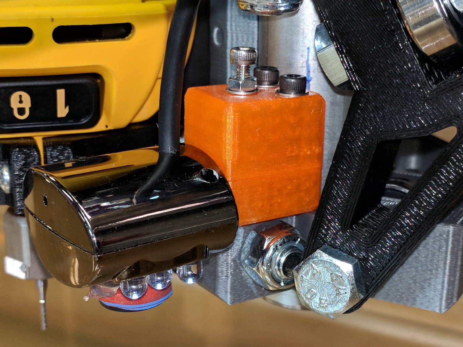
|
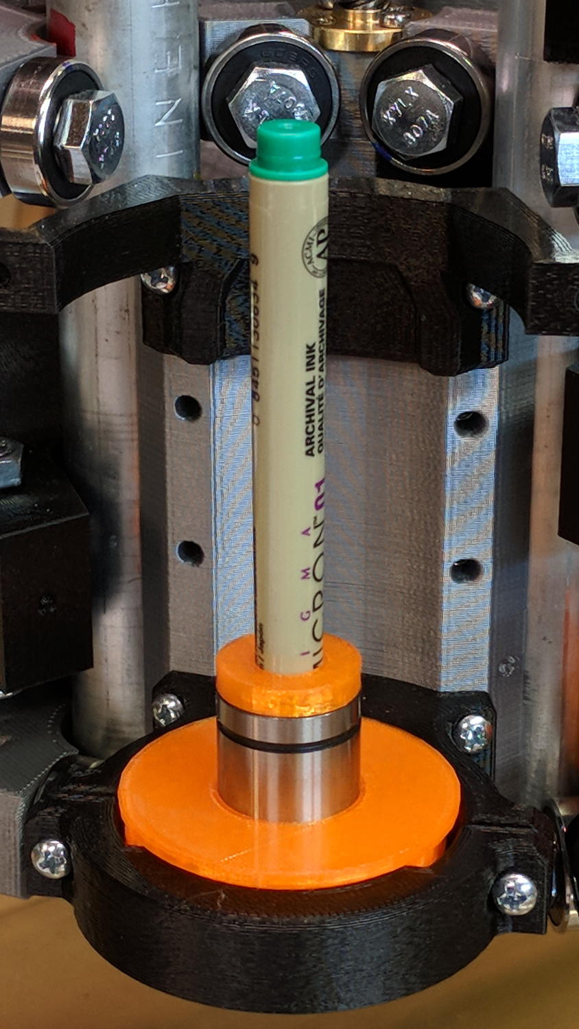
// MPCNC Pen Holder for DW660 Mount |
|
// Ed Nisley KE4ZNU – 2018-03-05 |
|
|
|
Layout = "Build"; // Build, Show |
|
// Puck, MountBase, BuildBase |
|
// Pen, PenAdapter, BuildAdapter |
|
|
|
/* [Extrusion] */ |
|
|
|
ThreadThick = 0.25; // [0.20, 0.25] |
|
ThreadWidth = 0.40; // [0.40] |
|
|
|
/* [Hidden] */ |
|
|
|
Protrusion = 0.1; // [0.01, 0.1] |
|
|
|
HoleWindage = 0.2; |
|
|
|
inch = 25.4; |
|
|
|
function IntegerMultiple(Size,Unit) = Unit * ceil(Size / Unit); |
|
|
|
ID = 0; |
|
OD = 1; |
|
LENGTH = 2; |
|
|
|
//- Adjust hole diameter to make the size come out right |
|
|
|
module PolyCyl(Dia,Height,ForceSides=0) { // based on nophead's polyholes |
|
Sides = (ForceSides != 0) ? ForceSides : (ceil(Dia) + 2); |
|
FixDia = Dia / cos(180/Sides); |
|
cylinder(r=(FixDia + HoleWindage)/2,h=Height,$fn=Sides); |
|
} |
|
|
|
//- Dimensions |
|
|
|
WallThick = 3.0; // minimum thickness / width |
|
|
|
Screw = [3.0,7.0,25.0]; // holding it all together, OD = washer |
|
|
|
Insert = [3.0,4.4,4.5]; // brass insert |
|
|
|
Bearing = [12.0,21.0,30.0]; // LM12UU bearing body, ID = rod OD |
|
|
|
PenTravel = 5.0; // vertical pen travel allowance |
|
|
|
NumSides = 8*4; // cylinder facets |
|
|
|
//—– |
|
// Define shapes |
|
|
|
//– Sakura Micron fiber-point pen |
|
|
|
ExpRP = 0.30; // expand critical sections (by radius) |
|
|
|
//– pen locates in holder against end of outer body |
|
|
|
PenOutline = [ |
|
[0,0], // 0 fiber pen tip |
|
[0.6/2,0.0],[0.6/2,0.9], // 1 … cylinder |
|
[1.5/2,0.9],[1.5/2,5.3], // 3 tip surround |
|
[4.7/2,5.8], // 5 chamfer |
|
[4.9/2,12.3], // 6 nose |
|
// [8.0/2,12.3],[8.0/2,13.1], // 7 latch ring |
|
// [8.05/2,13.1],[8.25/2,30.5], // 9 actual inner body |
|
[8.4/2 + ExpRP,12.3],[8.4/2 + ExpRP,30.5], // 7 inner body – clear latch ring |
|
[9.5/2 + ExpRP,30.9], // 9 outer body – location surface! |
|
[9.8/2 + ExpRP,60.0], // 10 outer body – length > Body |
|
[7.5/2,60.0], // 11 arbitrary length, much longer than bearing |
|
[7.5/2,59.0], // 12 end of reservoir |
|
[0,59.0] // 13 fake reservoir |
|
]; |
|
|
|
PenNose = PenOutline[6][1]; |
|
PenLocate = PenOutline[9][1]; |
|
|
|
// Basic shape of DW660 snout fitting into the holder |
|
// Lip goes upward to lock into MPCNC mount |
|
|
|
Snout = [44.6,50.0,9.6]; // LENGTH = ID height |
|
Lip = 4.0; // height of lip at end of snout |
|
Key = [Snout[ID],25.7,Snout[LENGTH] + Lip]; // rectangular key |
|
|
|
module DW660Puck() { |
|
|
|
cylinder(d=Snout[OD],h=Lip/2,$fn=NumSides); |
|
translate([0,0,Lip/2]) |
|
cylinder(d1=Snout[OD],d2=Snout[ID],h=Lip/2,$fn=NumSides); |
|
cylinder(d=Snout[ID],h=Lip + Snout[LENGTH],$fn=NumSides); |
|
intersection() { |
|
translate([0,0,0*Lip + Key.z/2]) |
|
cube(Key,center=true); |
|
cylinder(d=Snout[OD],h=Lip + Key.z,$fn=NumSides); |
|
} |
|
|
|
} |
|
|
|
module MountBase() { |
|
|
|
difference() { |
|
DW660Puck(); |
|
translate([0,0,-Protrusion]) |
|
PolyCyl(Bearing[OD],2*Bearing[LENGTH],NumSides); |
|
} |
|
} |
|
|
|
//– Sakura drawing pen body & polygon shape |
|
|
|
module Pen() { |
|
rotate_extrude($fn=NumSides) |
|
polygon(points=PenOutline); |
|
polygon(points=PenOutline); |
|
} |
|
|
|
//– Pen holder |
|
|
|
AdapterRing = [Bearing[ID],Bearing[OD],4.0]; |
|
AdapterOAL = Bearing[LENGTH] + PenTravel + AdapterRing[LENGTH]; |
|
|
|
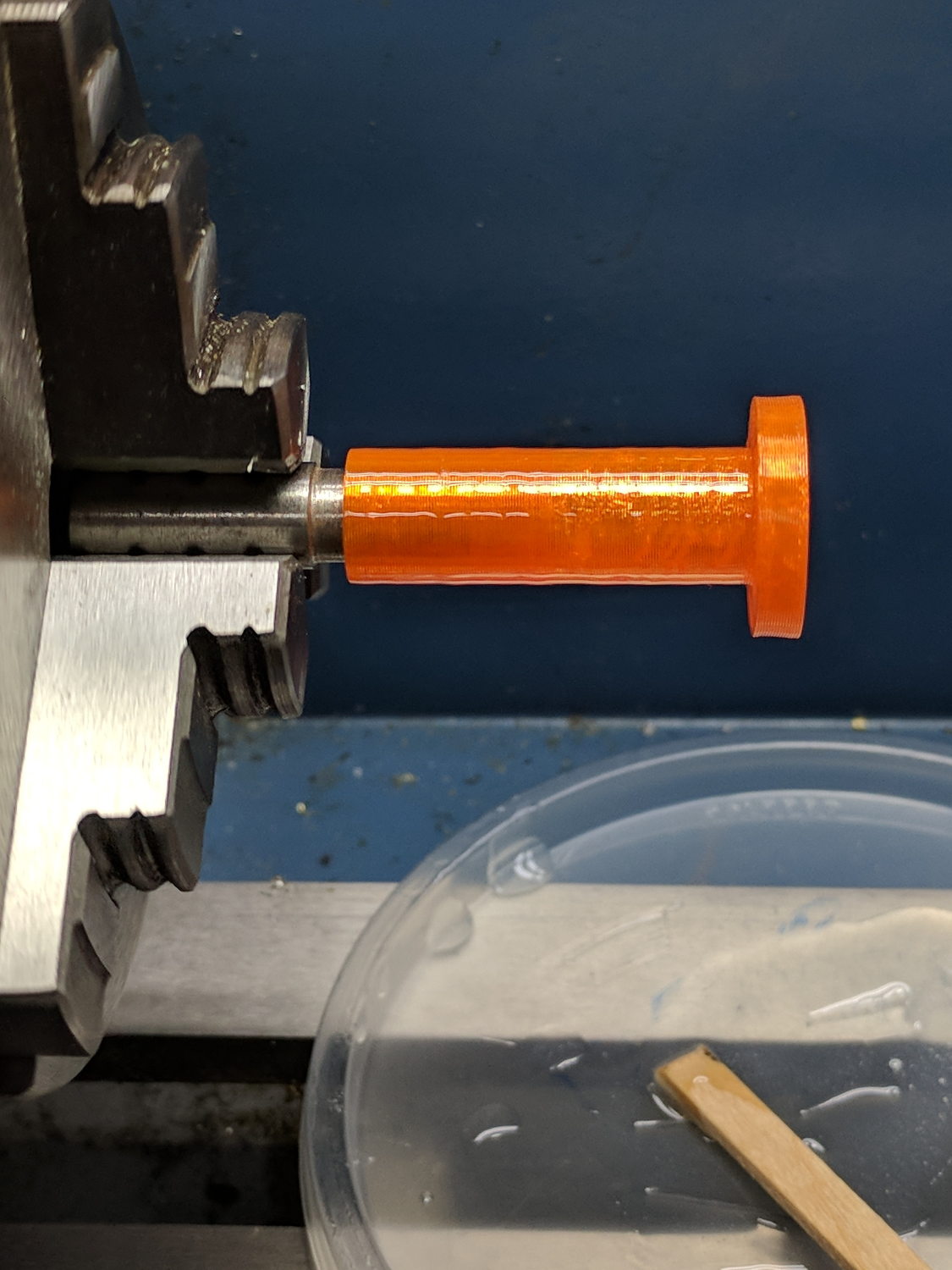
module PenAdapter() { |
|
|
|
difference() { |
|
union() { |
|
PolyCyl(Bearing[ID],AdapterOAL,NumSides); |
|
translate([0,0,AdapterOAL – AdapterRing[LENGTH]]) |
|
cylinder(d=AdapterRing[OD],h=AdapterRing[LENGTH],$fn=NumSides); |
|
} |
|
translate([0,0,-(PenNose + Protrusion)]) |
|
Pen(); |
|
} |
|
|
|
} |
|
|
|
//—– |
|
// Build it |
|
|
|
if (Layout == "Puck") |
|
DW660Puck(); |
|
|
|
if (Layout == "MountBase") |
|
MountBase(); |
|
|
|
if (Layout == "Pen") |
|
Pen(); |
|
|
|
if (Layout == "PenAdapter") |
|
PenAdapter(); |
|
|
|
if (Layout == "Show") |
|
MountBase(); |
|
|
|
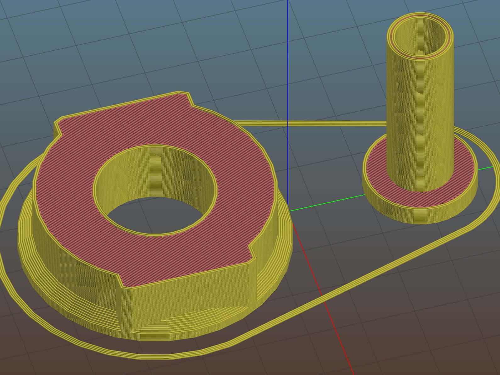
if (Layout == "BuildBase" || Layout == "Build") |
|
translate([0,-Snout[OD]/2,0]) |
|
MountBase(); |
|
|
|
if (Layout == "BuildAdapter" || Layout == "Build") |
|
translate([0,Snout[OD]/2,AdapterOAL]) |
|
rotate([180,0,0]) |
|
PenAdapter(); |