For reasons not relevant here, I had to wake up a New Old Stock bottle of an eye drug dispensed as a suspension in a small bottle:
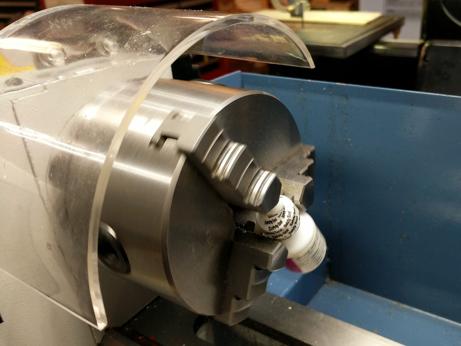
A few hours at 50 RPM and it’s all shook up.
The Smell of Molten Projects in the Morning
Ed Nisley's Blog: Shop notes, electronics, firmware, machinery, 3D printing, laser cuttery, and curiosities. Contents: 100% human thinking, 0% AI slop.
Mechanical widgetry
For reasons not relevant here, I had to wake up a New Old Stock bottle of an eye drug dispensed as a suspension in a small bottle:
A few hours at 50 RPM and it’s all shook up.
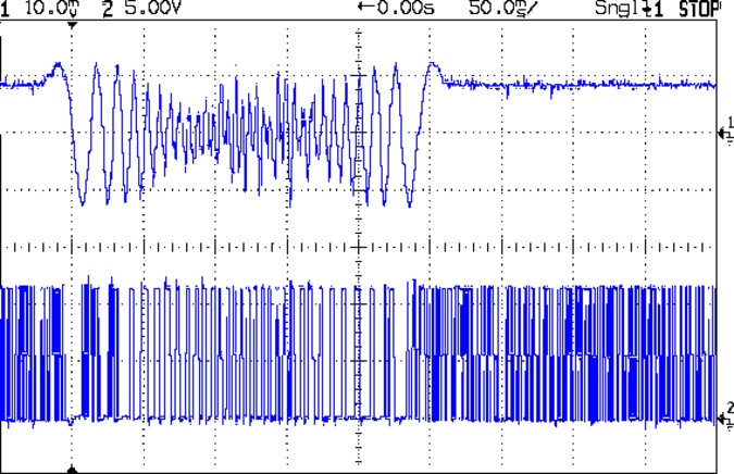
This is what the stepper current looks like when you run an MPCNC at 12000 mm/min = 200 mm/s from a 24 V supply:
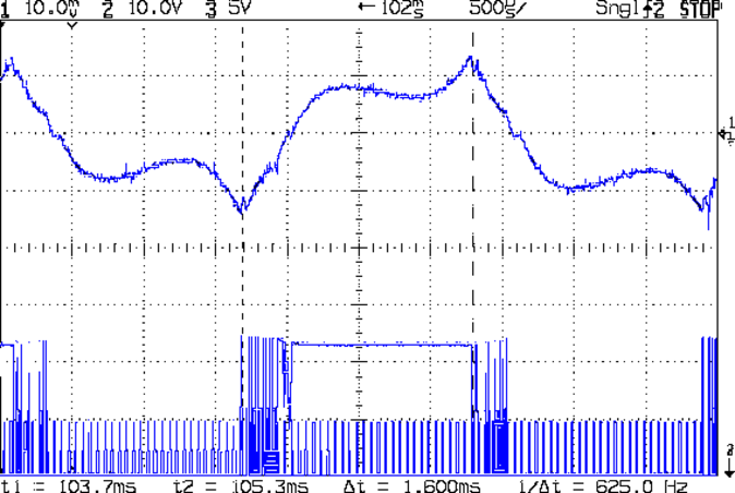
The vertical scale for the winding current in the top trace is 200 mA/div, so those flat sections run about 150 mA, well under the 600 mA peak found at lower speeds. This G0 move ramps up to 12000 mm/min and shows the current falling off and the sine wave deteriorating:
The motor turns at 375 RPM, which means each stepper generates 12 Vpk back EMF, so the A4988 driver has absolutely no control authority near what should be the zero crossings of the current waveform.
The taller waveform along the bottom of the first scope shot comes from the H bridge output tending to increase the current waveform, so it’s applying a solid +24 during the flat top section and not only gets no traction, but actually loses ground just after the middle of the screen. Eventually the back EMF drops and the current begins increasing, but long after what should be the 600 mA peak current where the driver flips the H bridge and begins trying to decrease the current.
Here’s a detailed view of the section just after the left cursor:
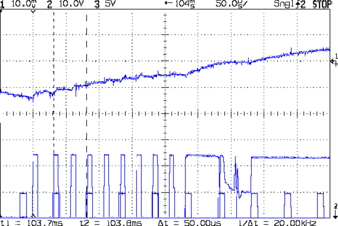
The step pulses tick along at 50 μs intervals, with only two driver PWM pulses for each one.
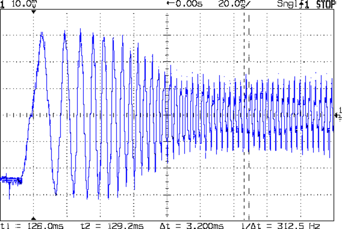
A 2-flute carbide cutter spinning at 20000 RPM with a 0.25 mm chip load calls for a speed of 10000 mm/min. Alas, the stock 12 V supply stalls at 8000 mm/min:
It’s facing something over 9 V of back EMF from the motors at that speed. The chaotic spikes near the middle of the current waveform show where the rotor dropped out of lock with the driver and begins shoving the current around.
So that’s why you really can’t use a 12 V power supply with series stepper motors, at least if you want to run ’em at more than moderate speeds. It’s not at all clear the 24 V supply will provide enough motor torque to run at 10 k mm/min, so I gotta wrap an enclosure around the electronics and start making some chips to see how it behaves …
PLA isn’t particularly strong, especially in small sections under high stress:

I tried solvent-bonding + clamping the break, didn’t expect much, and wasn’t disappointed.
It adds a festive touch when done up in orange PETG:
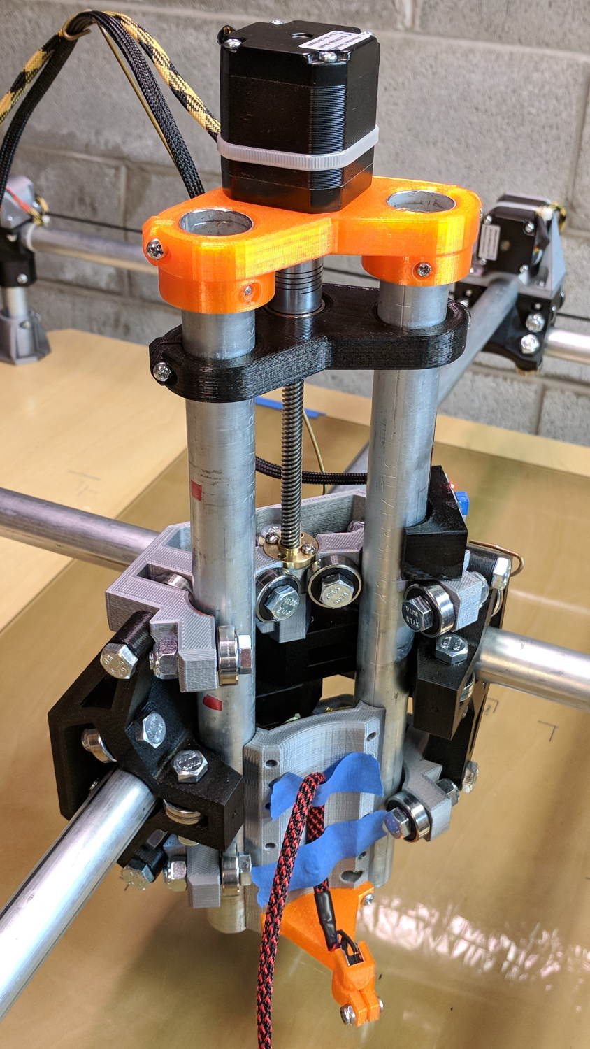
The attentive reader will note the missing head of the screw anchoring the mount to the left Z rail. Apparently a #32 drill was a bit too small to let the randomly chosen self-tapping screws thread themselves into EMT; they probably anchored a PCB to the plastic case of a long-forgotten lump of consumer electronics.
It should last long enough for something else to let go …
Two more umbrella struts snapped and required the same repair, but, having drained all the suitable snippets from the Box o’ Brass Cutoffs, some lathe work was in order:

I used the carbide insert in the mistaken belief it’d be less grabby, then applied the cutoff tool.
Break the edges, slide splints over the ribs, slobber epoxy on the struts, slide splints into place, apply masking tape for a bit of compression & alignment, and let it cure:

Three down, five to go …
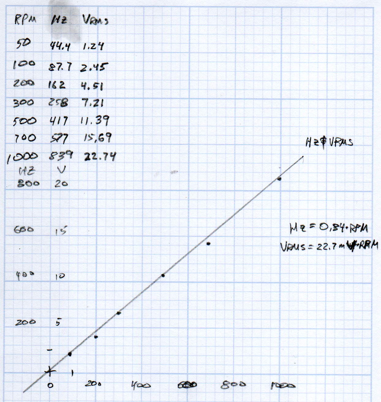
A plot of the back EMF for an Automation Technology KL17H248-15-4A stepper motor looks like I’m making stuff up again:
Maybe the only questions I ask are ones with linear solutions?
Anyhow, the data comes from the Z-axis motor in the lathe:
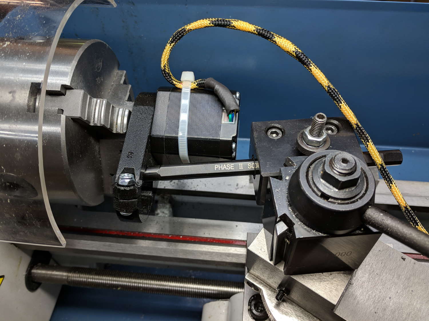
Scary-looking, but reasonably safe. The chuck holds the motor shaft so it’s not going anywhere, the boring bar prevents any rotation, and the motor bearings do exactly what they’re supposed to. Shorting the motor leads would definitely put a hurt on the PLA frame, so I didn’t do that.
The scope sat on the floor beside the lathe, capturing waveforms and doing calculations:

Some waveforms look bent:

I asked the scope to measure the RMS voltage, rather than the peak, because it’s less sensitive to distortions.
Each winding produces one electrical cycle across four mechanical full steps, with the windings in quadrature. One shaft revolution thus produces 200 / 4 = 50 electrical cycles, so converting from shaft RPM into electrical cycles/s goes a little something like this:
Electrical cycles/s = (shaft rev/min) * (50 cycles/rev) / 60 (s/min)
Which works out to a tidy 0.833 Hz/RPM, basically spot on the last data point’s 839 Hz at 1000 RPM.
The motivation for this comes from the third column in the scribbles: back EMF = 22.7 mVrms/RPM = 32 mVpk/RPM.
A rapid move at 12 k mm/min = 200 mm/s shows the motor current collapsing to the ragged edge of not working:
Converting motor speed to shaft RPM:
RPM = (axis mm/s) / (32 mm/rev) * (60 s/min)

RPM = (axis mm/min) / (32 mm/rev)
So the shaft turns at 375 RPM when the X axis moves at 12 k mm/min, with each motor generating 8.5 Vrms = 12 Vpk of back EMF.
The MPCNC wires the two motors on each axis in series, so the 24 V power supply faces 24 V of back EMF (!) from both motors, leaving exactly nothing to push the winding current around. Because the highest EMF occurs at the zero crossing points of the (normal) winding current, I think the current peaks now occur there, with the driver completely unable to properly shape the current waveform.
What you see in the scope shot is what actually happens: the current stabilizes at a ragged square-ish wave at maybe 300 mA (plus those nasty spikes). More study is needed.
We just scrapped out the old dish drainer, only to find the gadget bin on the new drainer let the measuring spoons fall over and lie along its bottom. After a week of fishing them out from under paring knives, cheese slicers, and suchlike, I gimmicked up a holder:

One might suggest natural PETG, rather than orange, thereby displaying a shocking ignorance of the MVP concept. We’ll run with orange for the shakedown trials, then build-measure-learn, iterate, and, for all I know, we may even pivot.
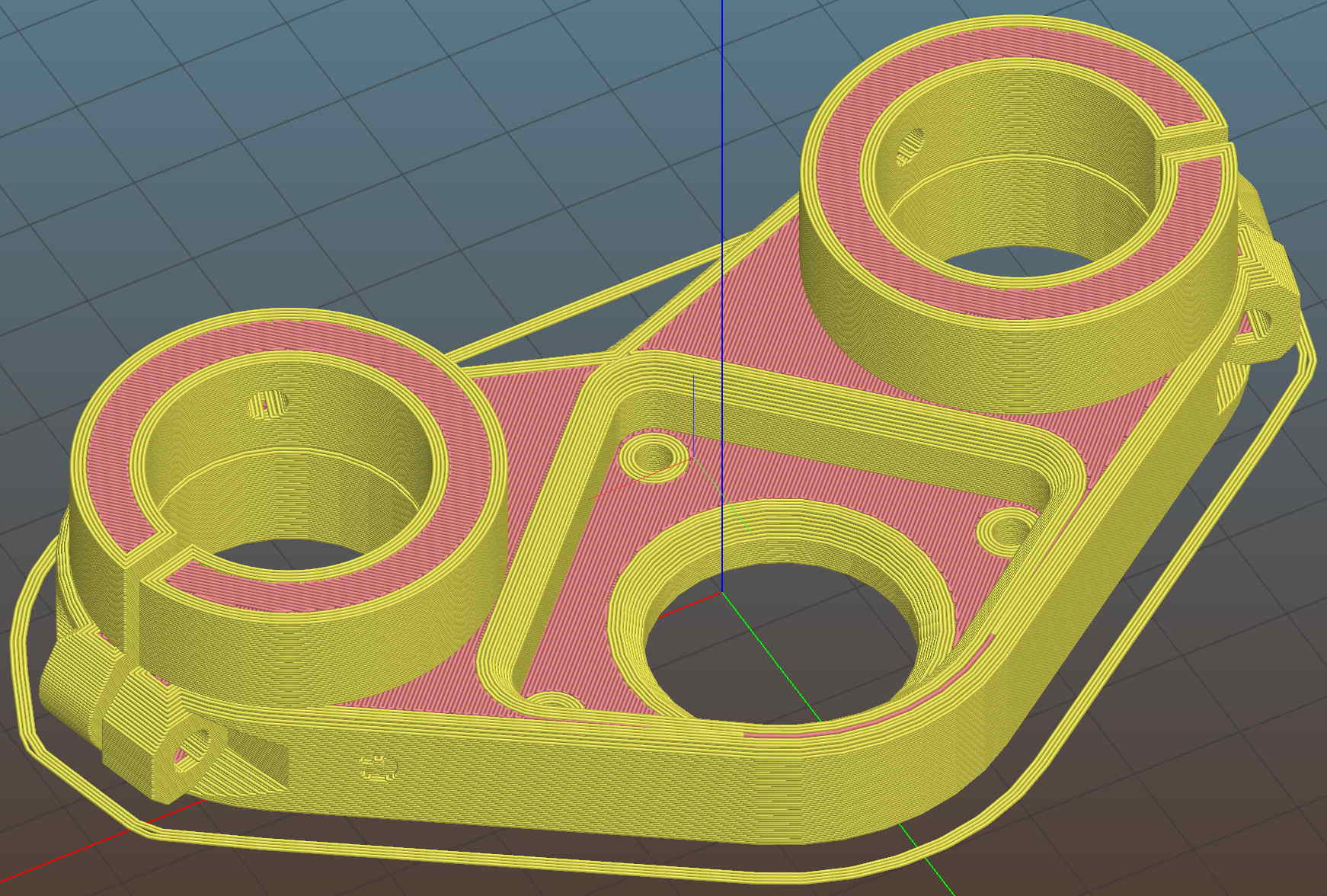
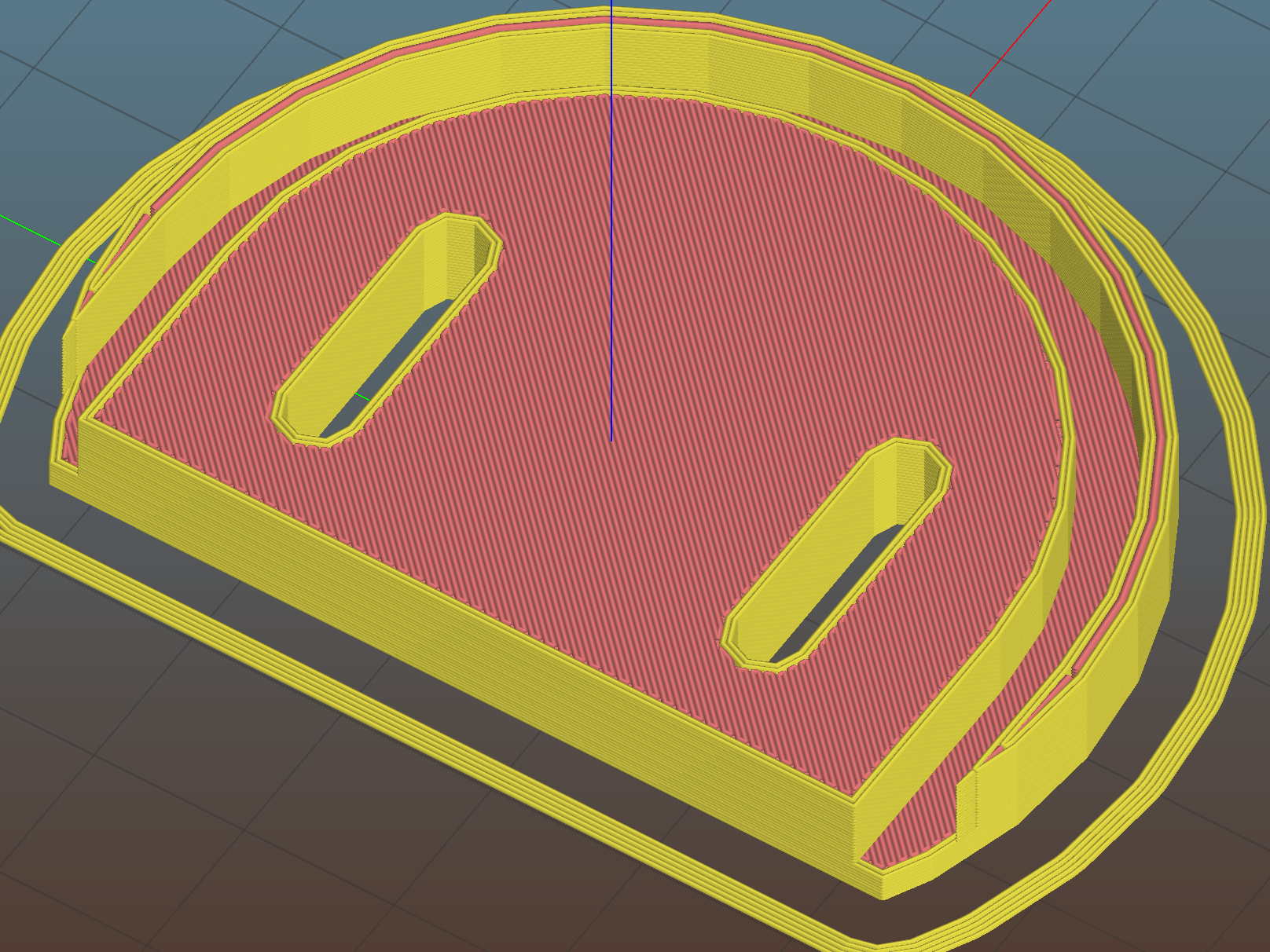
A bottom-up view of the solid model shows the trench accommodating the bin lip:
The OpenSCAD source code as a GitHub Gist:
| // Measuring spoon drainer | |
| // Ed Nisley KE4ZNU – 2018-01-13 | |
| /* [Extrusion] */ | |
| ThreadThick = 0.25; // [0.20, 0.25] | |
| ThreadWidth = 0.40; // [0.40] | |
| /* [Hidden] */ | |
| Protrusion = 0.1; // [0.01, 0.1] | |
| HoleWindage = 0.2; | |
| function IntegerMultiple(Size,Unit) = Unit * ceil(Size / Unit); | |
| ID = 0; | |
| OD = 1; | |
| LENGTH = 2; | |
| //- Adjust hole diameter to make the size come out right | |
| module PolyCyl(Dia,Height,ForceSides=0) { // based on nophead's polyholes | |
| Sides = (ForceSides != 0) ? ForceSides : (ceil(Dia) + 2); | |
| FixDia = Dia / cos(180/Sides); | |
| cylinder(r=(FixDia + HoleWindage)/2,h=Height,$fn=Sides); | |
| } | |
| /* [Spoon] */ | |
| SpoonOD = IntegerMultiple(3.3,2); | |
| SpoonWidth = IntegerMultiple(16.5,2.0); | |
| SpoonOC = 30.0; | |
| /* [Drainer] */ | |
| Drainer = [52.0,59.5,100.0]; // overall drainer cup | |
| DrainerRimWidth = (Drainer[1] – Drainer[0])/2; | |
| DrainerRimHeight = 2.5; | |
| DrainerExtent = 15.0; | |
| /* [Hidden] */ | |
| WallThick = 2.0; // basic wall & floor thickness | |
| PlateThick = WallThick + 2*DrainerRimHeight; | |
| NumSides = 8*4; | |
| //—– | |
| // Define shapes | |
| module CoverPlate() { | |
| OD = Drainer[OD] + 2*WallThick; | |
| difference() { | |
| cylinder(d=OD,h=PlateThick,$fn=NumSides); | |
| for (j=[-1,1]) | |
| translate([-(OD/2 – Protrusion),j*(Drainer[ID]/2 + DrainerRimWidth/2),WallThick + DrainerRimHeight + Protrusion/2]) | |
| cube([OD,DrainerRimWidth,2*DrainerRimHeight + Protrusion],center=true); | |
| translate([0,0,WallThick + PlateThick/2]) | |
| rotate(-90) | |
| rotate_extrude(angle=180,$fn=NumSides) | |
| translate([Drainer[ID]/2 + DrainerRimWidth/2,0]) | |
| square([DrainerRimWidth,PlateThick],center=true); | |
| translate([-(OD/2 + DrainerExtent),0,PlateThick/2]) | |
| cube([OD,OD,PlateThick + 2*Protrusion],center=true); | |
| } | |
| } | |
| //—– | |
| // Build it | |
| difference() { | |
| CoverPlate(); | |
| for (j=[-1,1]) | |
| translate([0,j*(SpoonOC/2),-Protrusion]) | |
| linear_extrude(height=PlateThick + 2*Protrusion) | |
| hull() | |
| for (i=[-1,1]) | |
| translate([i*(SpoonWidth – SpoonOD)/2,0]) | |
| circle(d=SpoonOD,$fn=8); | |
| } | |
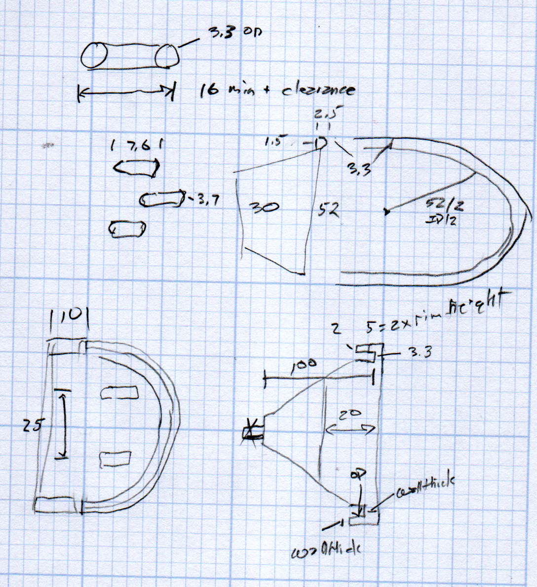
The original doodle has useful dimensions, along with the usual over-elaborate features sacrificed in order to get it made:
The MPCNC uses a DW660 Cutout tool as a low-cost spindle for tools with 1/8 and 1/4 inch shanks. It features a tool-free “collet grip” to twist the collet nut against the shaft lock, which is convenient for a hand tool and not so much for a CNC spindle: I find it difficult to get two hands into the MPCNC setup with the proper orientation to push-and-hold two locking buttons, while applying enough torque to twist the collet nut:

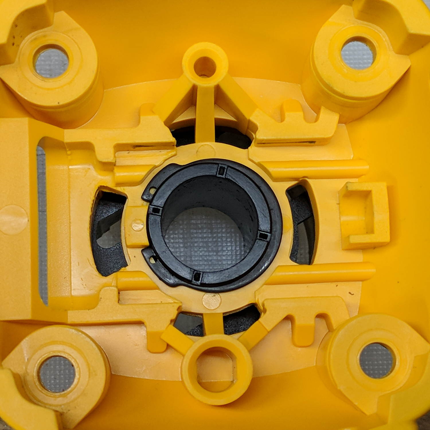
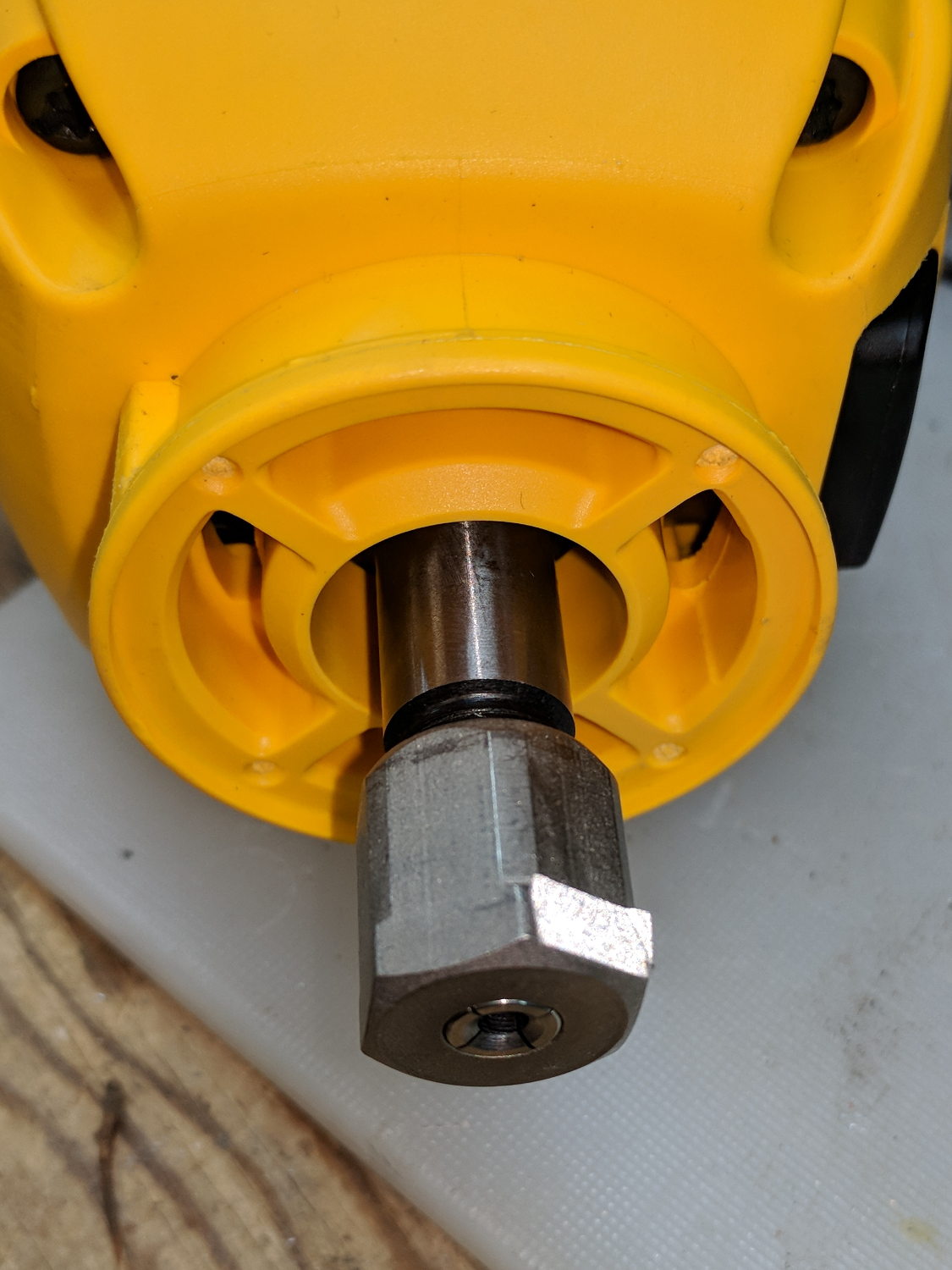
Fortunately, it’s easy enough to remove the collet grip. Remove the collet nut, unscrew the four screws holding the yellow snout in place, then pull the snout straight off to reveal the spindle lock plate:

Capture the spring, slide the spindle lock plate out to expose the snap ring (a.k.a. Jesus clip) holding the collet grip in place:
Remove the snap ring, make the appropriate remark, pull the collet grip out of the snout, reassemble the snout in its One Correct Orientation, and you’re done:
The retroreflective tape snippet let my laser tachometer report a top speed over 29 k rpm, pretty close to the advertised 30 k rpm.
If one were fussy, one would 3D print a thing to cover the snout’s open end:

The original snap ring holds it in place and the fancy pattern comes from octogram spiral infill on the bottom.
The collet nut fits either a 5/8 inch or 16 mm wrench, both of which stick out to the side far enough for a convenient hold while pressing the shaft lock button.
