Ed Nisley's Blog: Shop notes, electronics, firmware, machinery, 3D printing, laser cuttery, and curiosities. Contents: 100% human thinking, 0% AI slop.
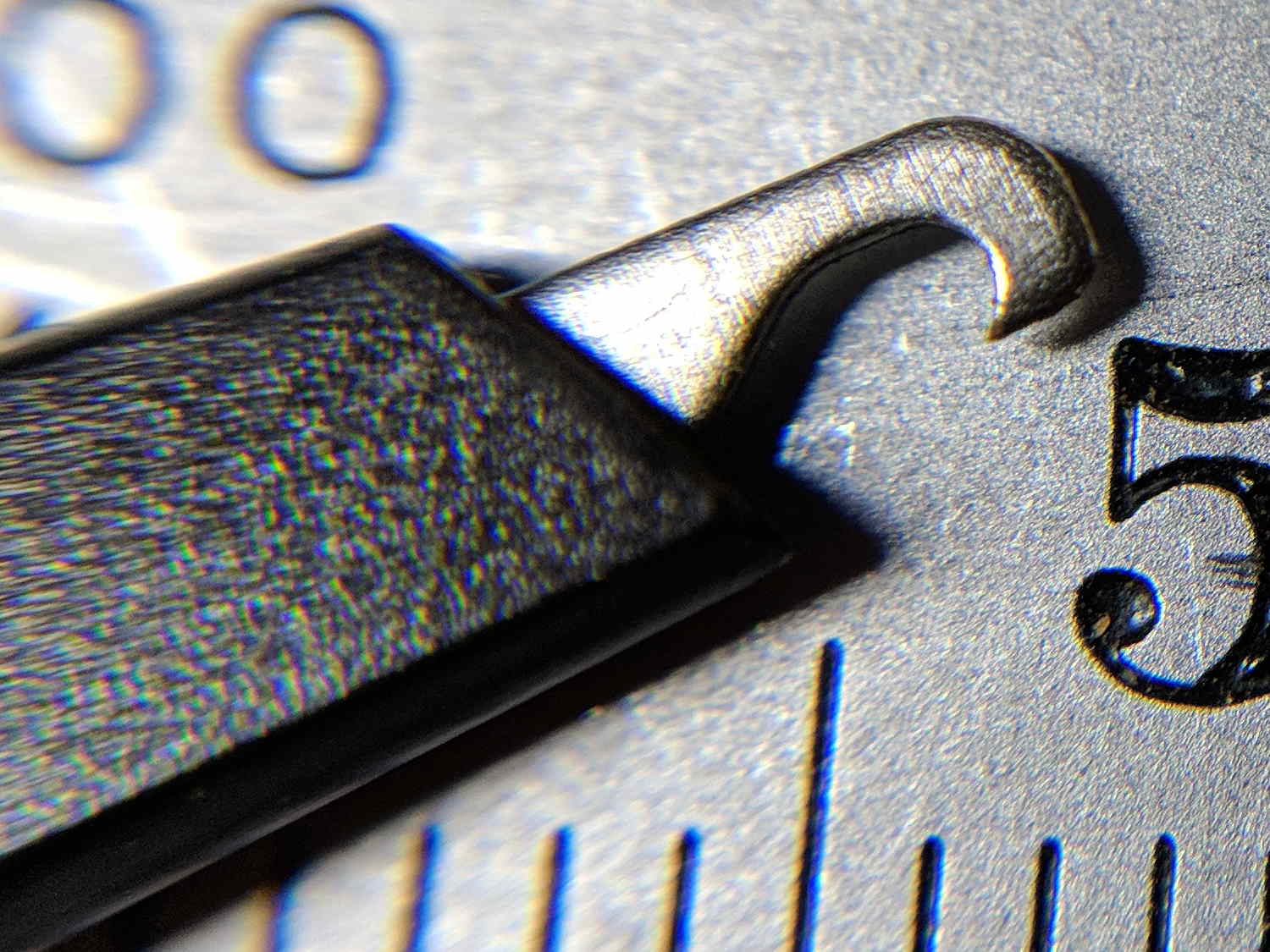
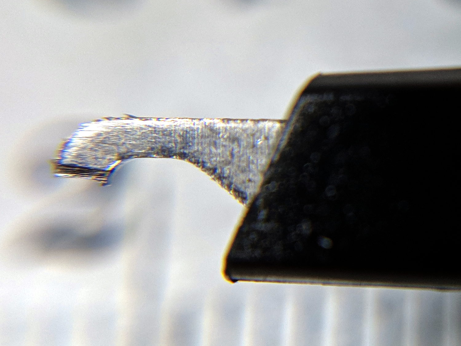
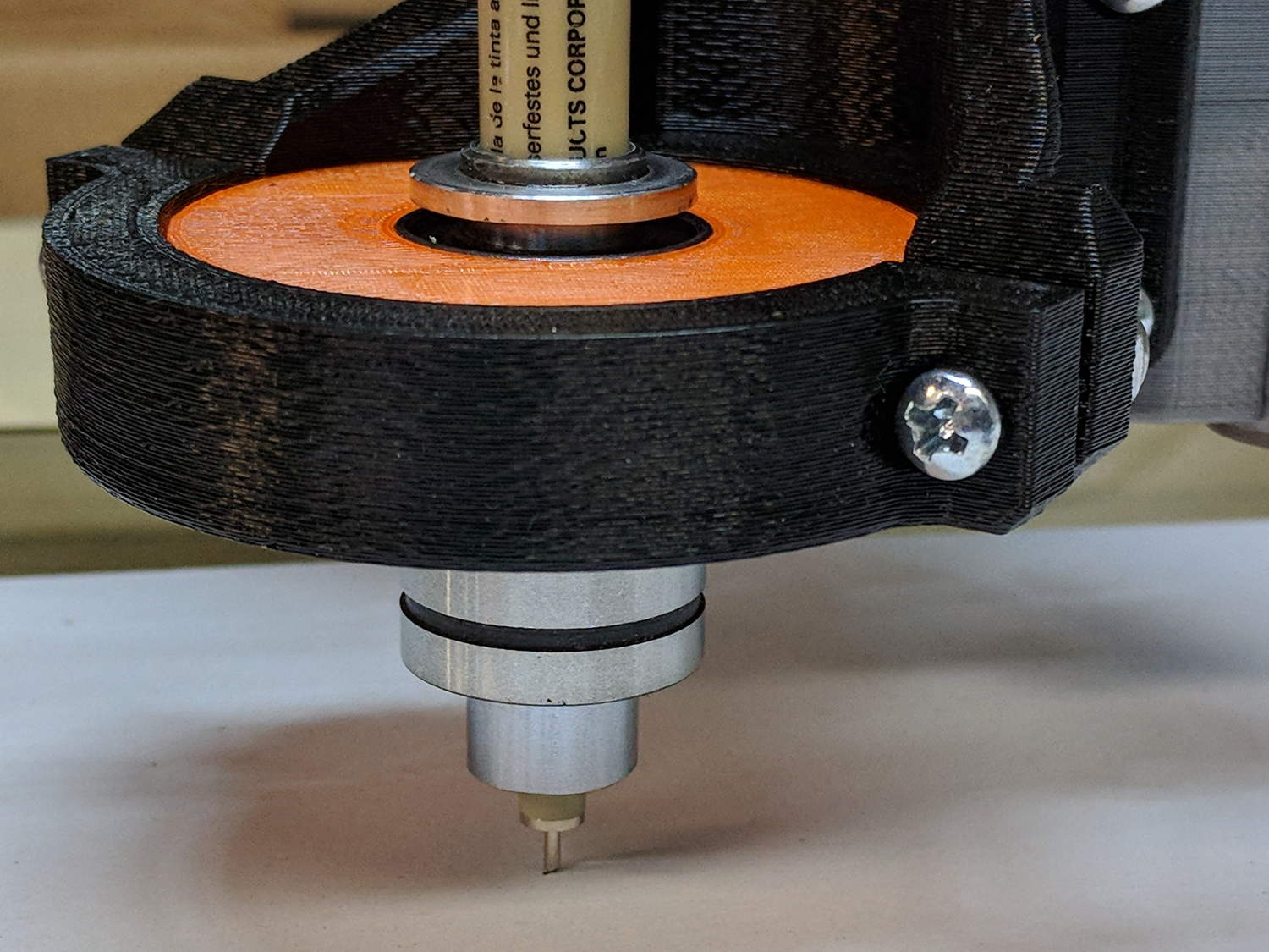
Drilling a pair of holes into a length of ground steel shaft turned it into a holder for a Sakura Micron pen:
DW660 Pen Holder – printed plastic vs ground steel
The aluminum ring epoxied to the top keeps it from falling completely through the linear bearing.
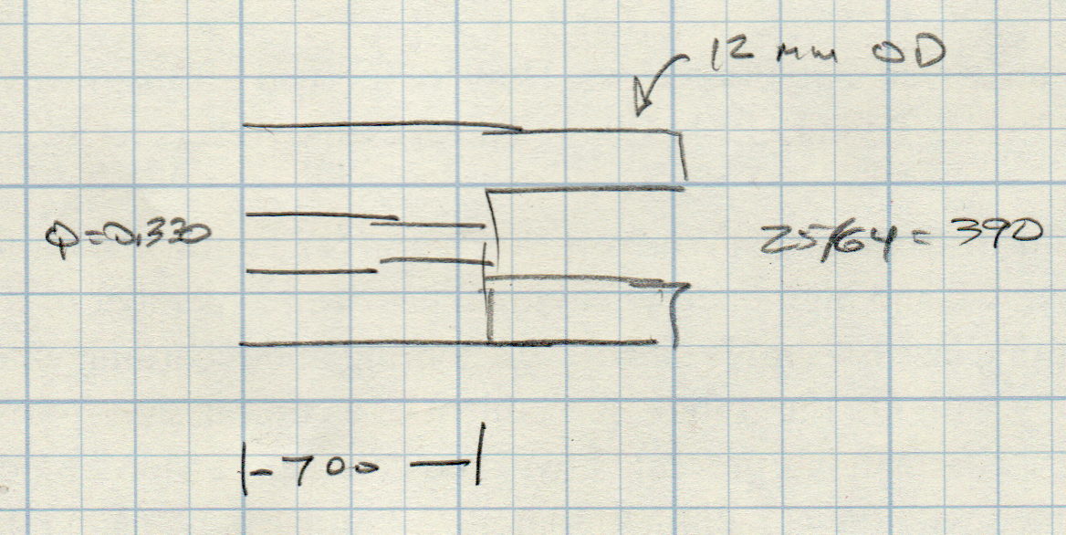
The hole sizes are the nearest inch drills matching the pen’s hard metric sizes:
Ground 12 mm rod – Sakura pen drill diameters
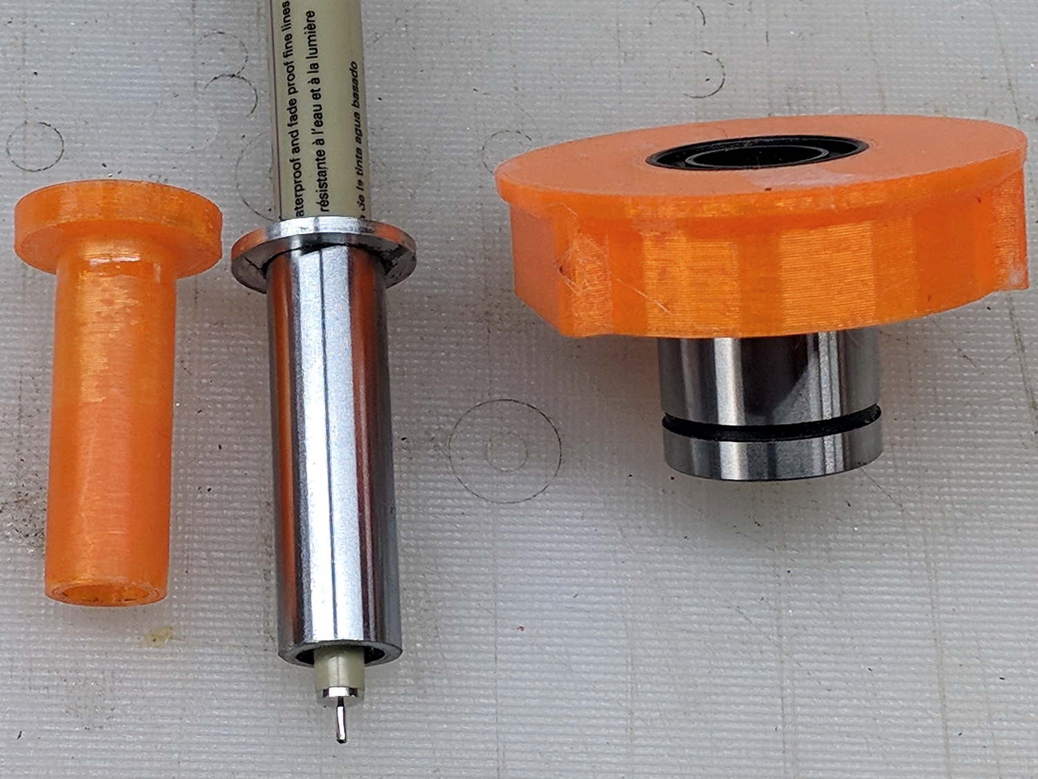
While I was at the lathe, I turned another layer of epoxy on the printed holder down to a consistent 11.95+ OD. It fits the bearing nearly as well as the steel shaft, although it’s not quite as smooth.
The steel version weighs about 20 g with the pen, so it applies about the same downforce on the pen nib as the HP 7475A plotter. The force varies from about 19 g as the Z axis moves upward to 23 g as it move downward, so the stiction amounts to less than 10% of the weight:
DW660 Pen Holder – ground shaft
However, the more I ponder this setup, the less I like it.
When the Z-axis moves downward and the nib hits the paper, it must decelerate the weight of the pen + holder + ballast within a fraction of a millimeter, without crushing the nib. If the pen moves downward at 3000 mm/min = 50 mm/s, stopping in 0.3 mm requires an acceleration of 4.2 m/s² and a 20 g = 2/3 oz mass will apply 0.08 N = 0.3 oz to the nib. Seems survivable, but smashing the tip a few hundred times while drawing the legends can’t possibly be good for it.
Also, the tool length probe switch trips at 60 (-ish) g, which means the pen can’t activate the switch. Adding a manual latch seems absurd, but you can get used to anything if you do it enough.
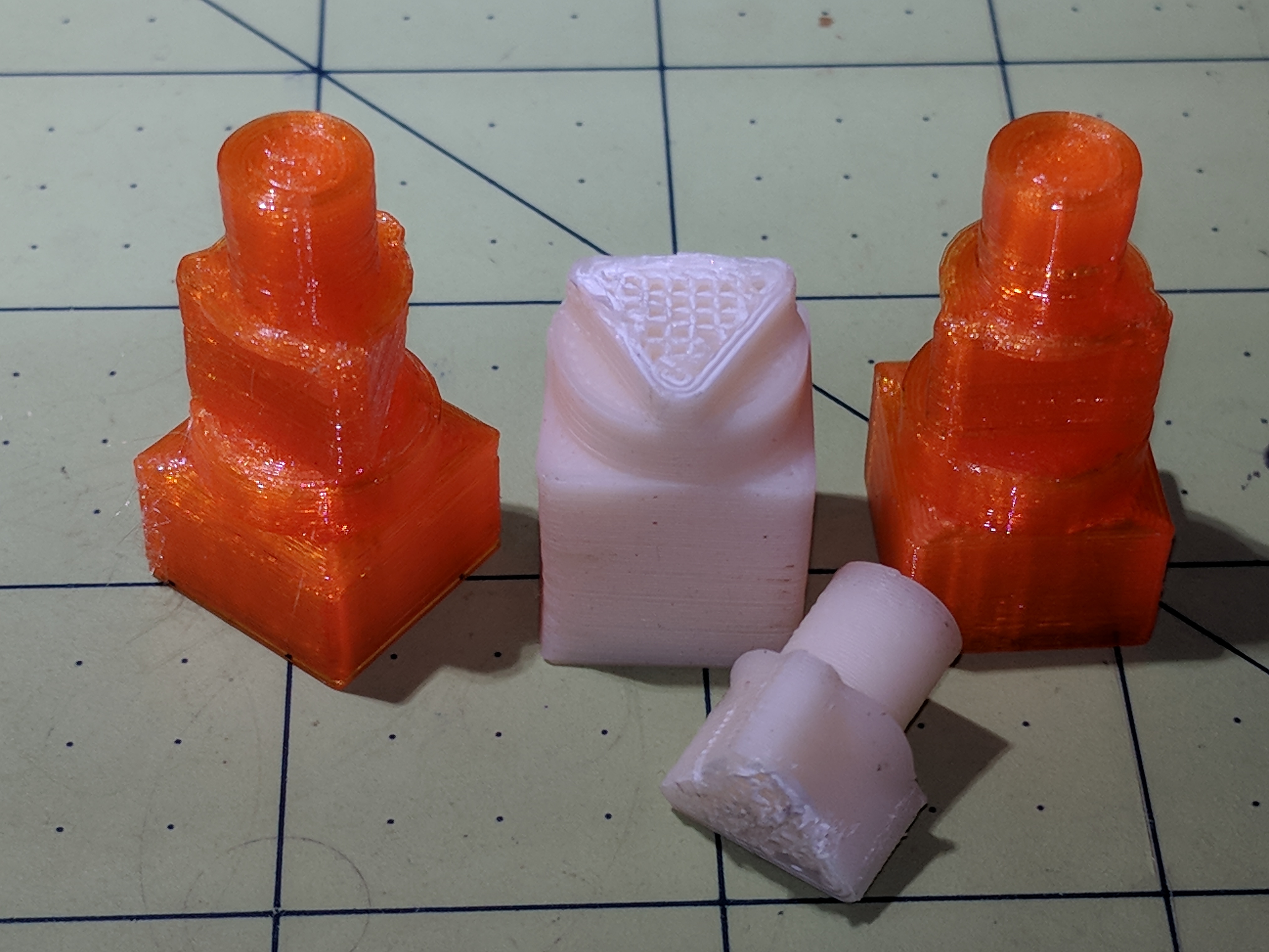
Smoking bacon during the winter months brought the third tank into play, requiring the POL-to-QD adapter I’d had in the drawer for just such an occasion. Not much to my surprise, the old PLA fitting adapter snapped along the layers near the outside end of the triangular snout:
IMG_20180408_125018
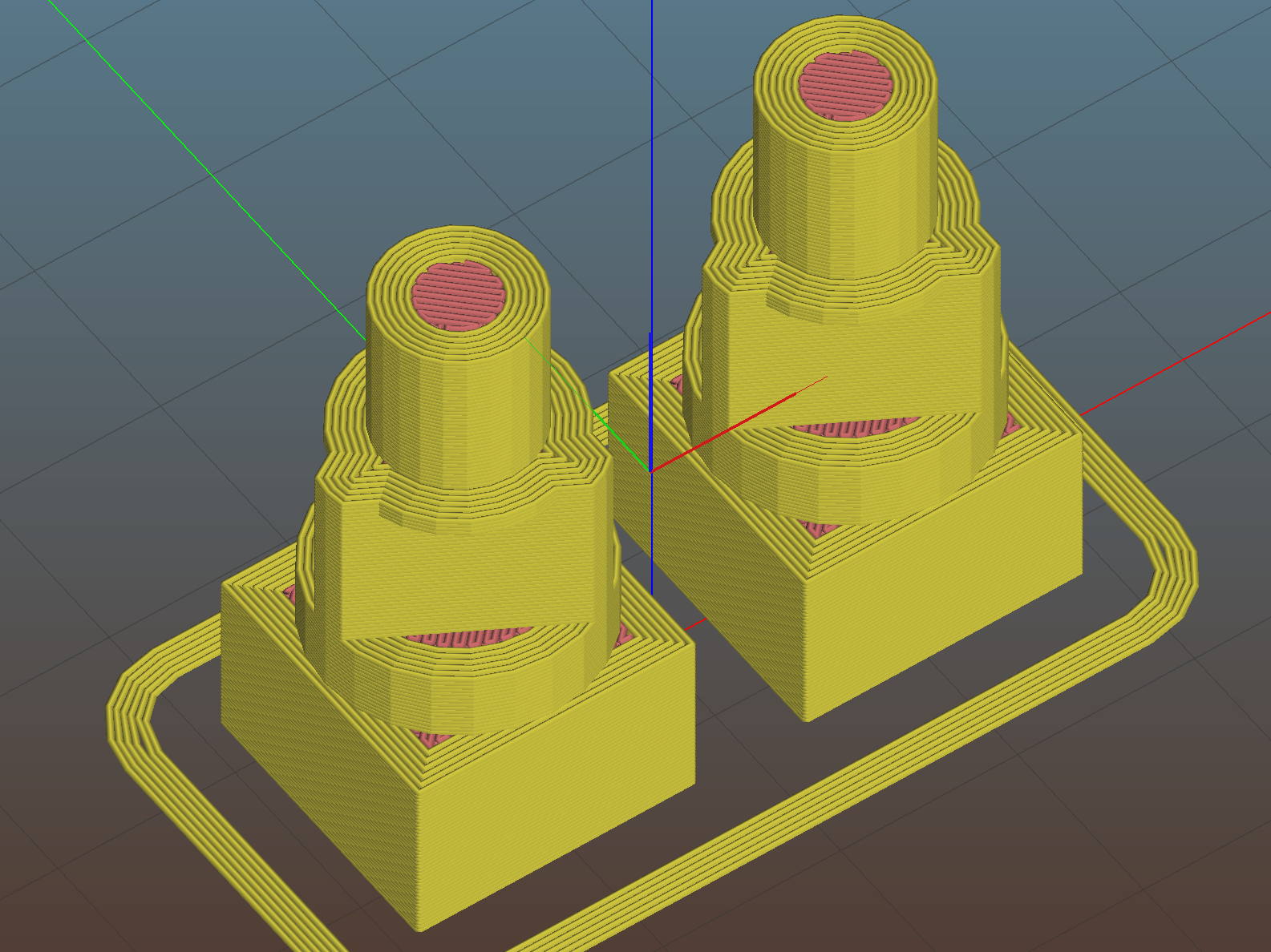
So I ran off the two orange ones in PETG with six perimeter layers and 50% infill density:
This file contains hidden or bidirectional Unicode text that may be interpreted or compiled differently than what appears below. To review, open the file in an editor that reveals hidden Unicode characters.
Learn more about bidirectional Unicode characters
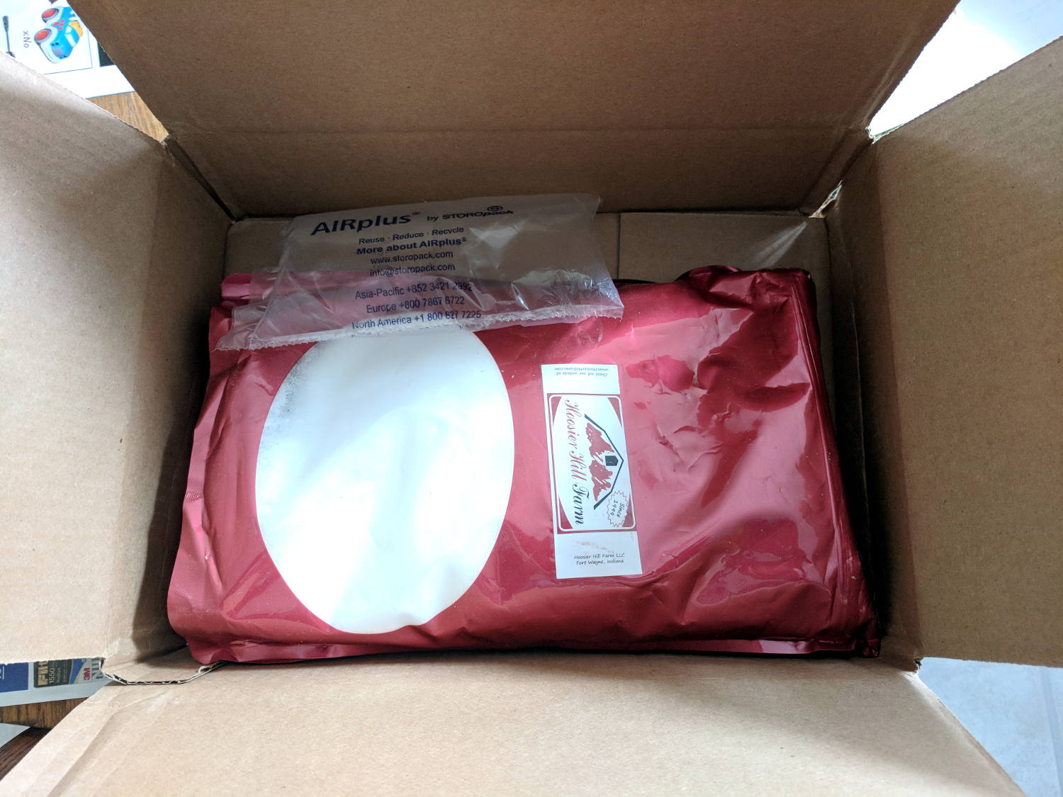
I have often kvetched about Amazon’s casual approach to packaging, so this took me completely by surprise:
Amazon packaging – 16 mm linear motion rod
There’s a 500 mm length of 16 mm round linear motion rod / shaft inside the small blue-and-white box. Previous shipments of similar rod have arrived in a lightly padded envelope or rattling loose in a box of other stuff.
The small blue-and-white corrugated cardboard box contains a bag protecting the well-oiled shaft, with padded end caps preventing the shaft from escaping or whacking against anything.
The middle box is made from two U-shaped sheets of molded (not corrugated) fiberboard, with one rigid U stapled into those wood end caps, the other U fitting over the assembly, and plenty of packing tape securing the two. Enough bubble wrap fills the cavity to surround and completely immobilize the inner box.
FedEx carried the armored box from Thomson to an Amazon warehouse in February, so it wasn’t packed specifically for me.
The upper box is a standard Amazon corrugated carton, with slightly more than a token amount of paper packed around the fiberboard box. The paper didn’t completely immobilize the middle box, but did serve to keep it from rattling loose.
I paid twenty bucks for the rod, with “free” Amazon Prime shipping, and UPS delivered it in the usual two days.
The whole affair weighs 7 pounds. If I were to reship it to somebody using UPS 2nd Day, they’d charge me $39 just for the shipping.
I felt unworthy …
On the other paw, Amazon recently sent a dozen LED lights with a casual disregard for protection:
Amazon packaging – shredded LED lamp carton
Both ends of the carton were shredded, although all of the cardboard tubes and LED lamps remained still inside. Not all the tube end caps completed the journey, however.
The carton didn’t sport the usual Box Certificate mark found on all Amazon cartons and was made of brittle Chinese cardboard, so it was intended for protected shipping, perhaps inside a freight container, not as a business-to-consumer shipping box.
Somewhat to my surprise, all the LED lights worked, including several that shrugged off their tube caps, as in the upper right, or broke their white cardboard end plates, as in the rest. The plastic protectors on the LED pins served their purpose!
Amazon provided a partial refund when I filed Package Feedback, so they’re paying attention to damages.
Five pounds of granular erythritol fared better, with a token air pillow contributing nothing:
The sturdy metal enclosure ought to be good for something, I thought, so I rescued it from the trash.
One of the ten button-head screws galled in place and resisted a few days of penetrating oil, so I drilled it out:
Drilled-out button screw head
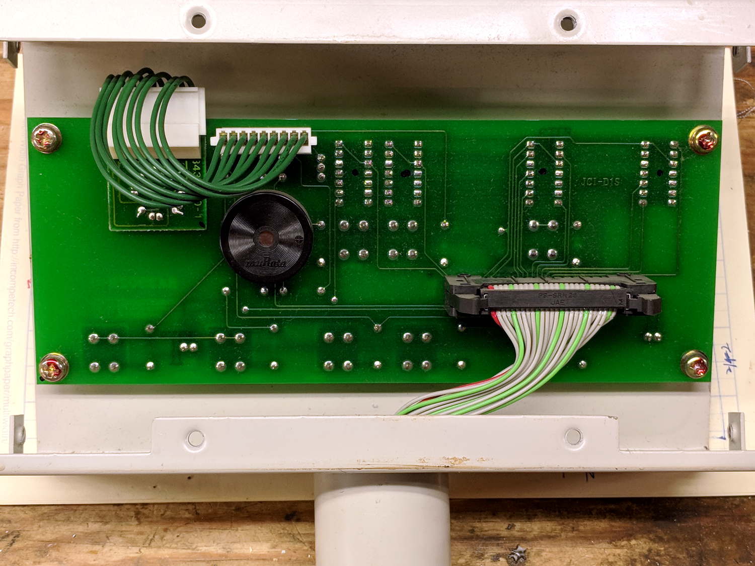
The PCB has no ICs! It simply routes all the LED and button pins through the pillar into the sewing machine controller:
Brother BAS-311 Control Head – interior
The ribbon cable alternates the usual flat strip with sections of split conductors:
Segmented ribbon cable
The split segments let it roll up into the pillar, with enough flexibility to allow rotating the head. I’ve seen segmented twisted-pair ribbon cable, but never just flat conductors.
Maybe the control head can become Art in its next life?
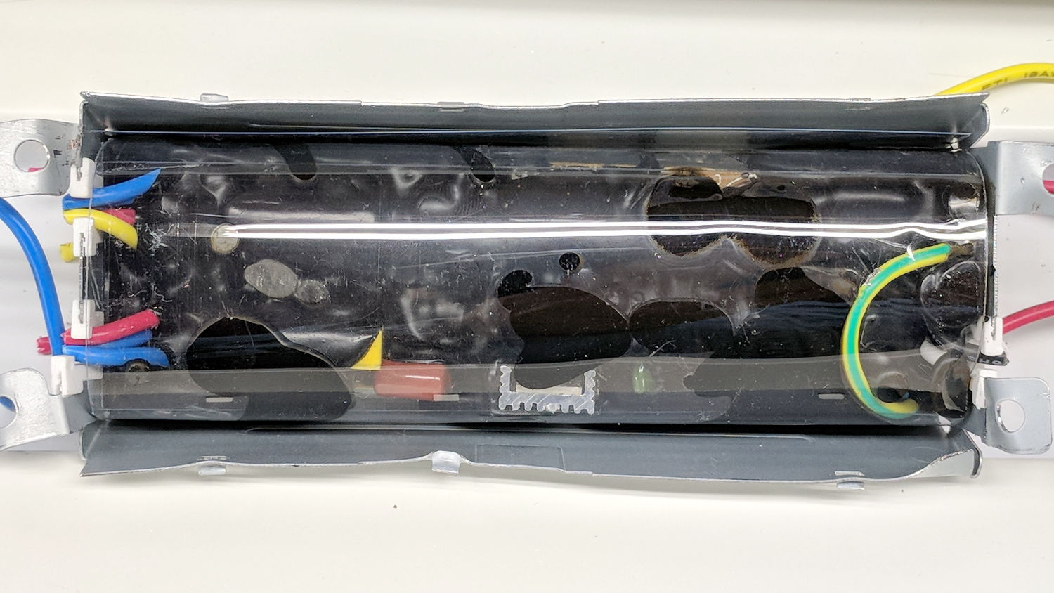
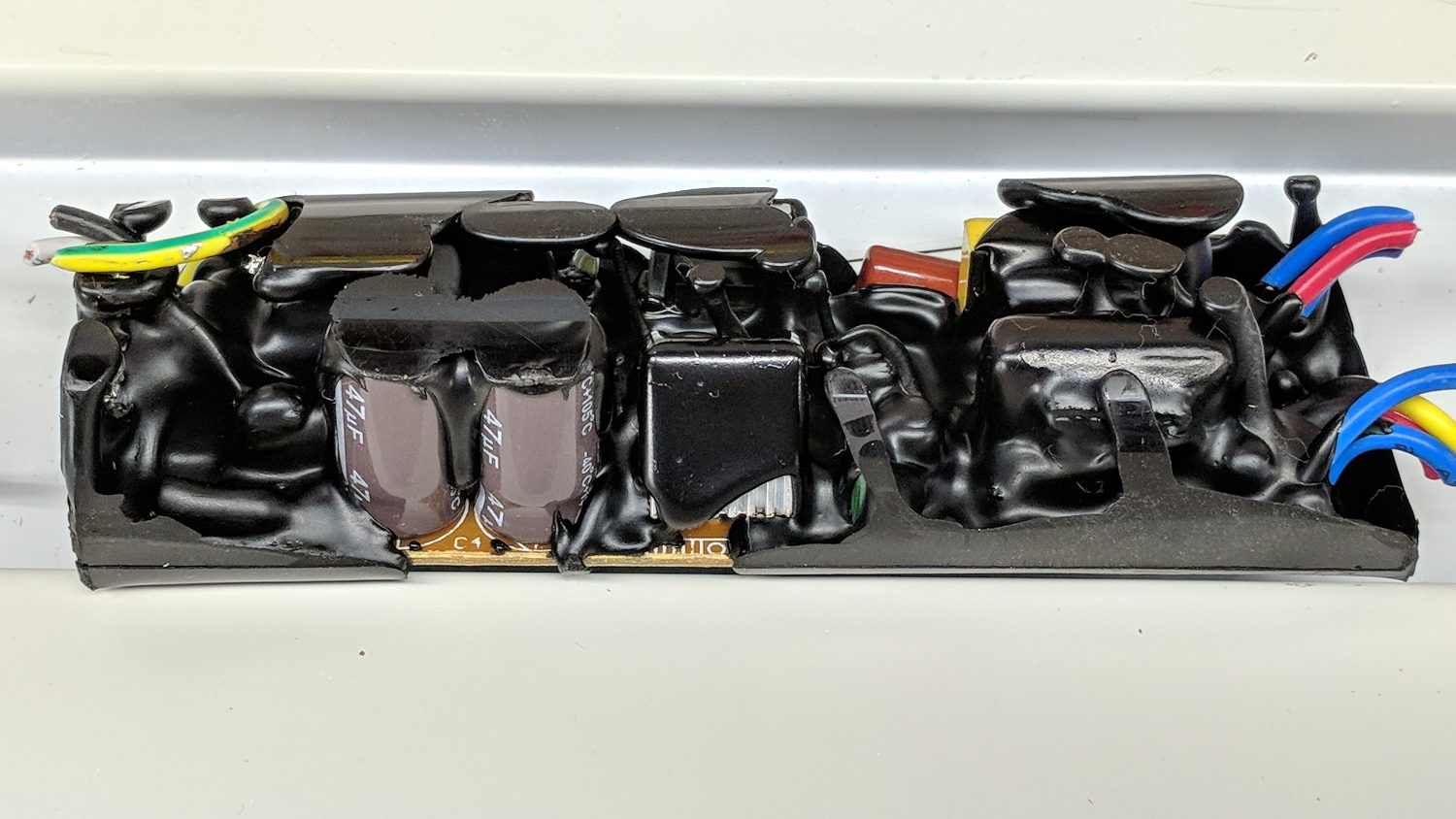
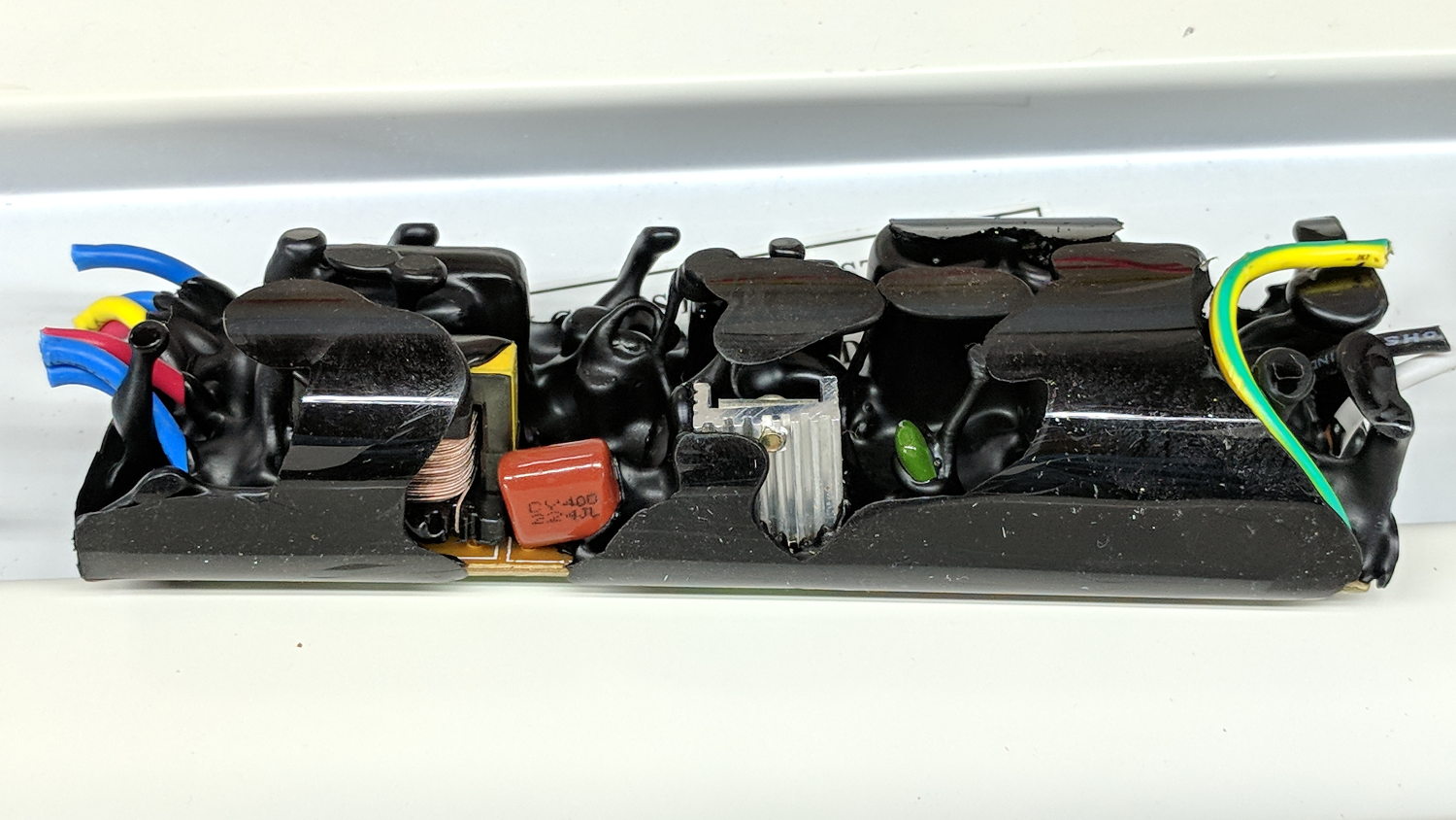
The black gunk smells more like plastic and less like old-school tar. It’s definitely not a peel-able conformal coating.
One the other paw, the two magnetic ballasts in another lamp sported actual metal-film capacitors, which I harvested and tossed into the Big Box o’ Film Caps:
Shoplight choke ballast – film cap
If a dying ballast didn’t also kill its fluorescent tube(s), I’d be less annoyed. I’m running the remaining tubes through the surviving fixtures, but the end is nigh for both.
The new LED tubes produce more light than the old fluorescents, although I still don’t like their 6500 K “daylight glow” color.