Well, a spider with half the proper leg count:
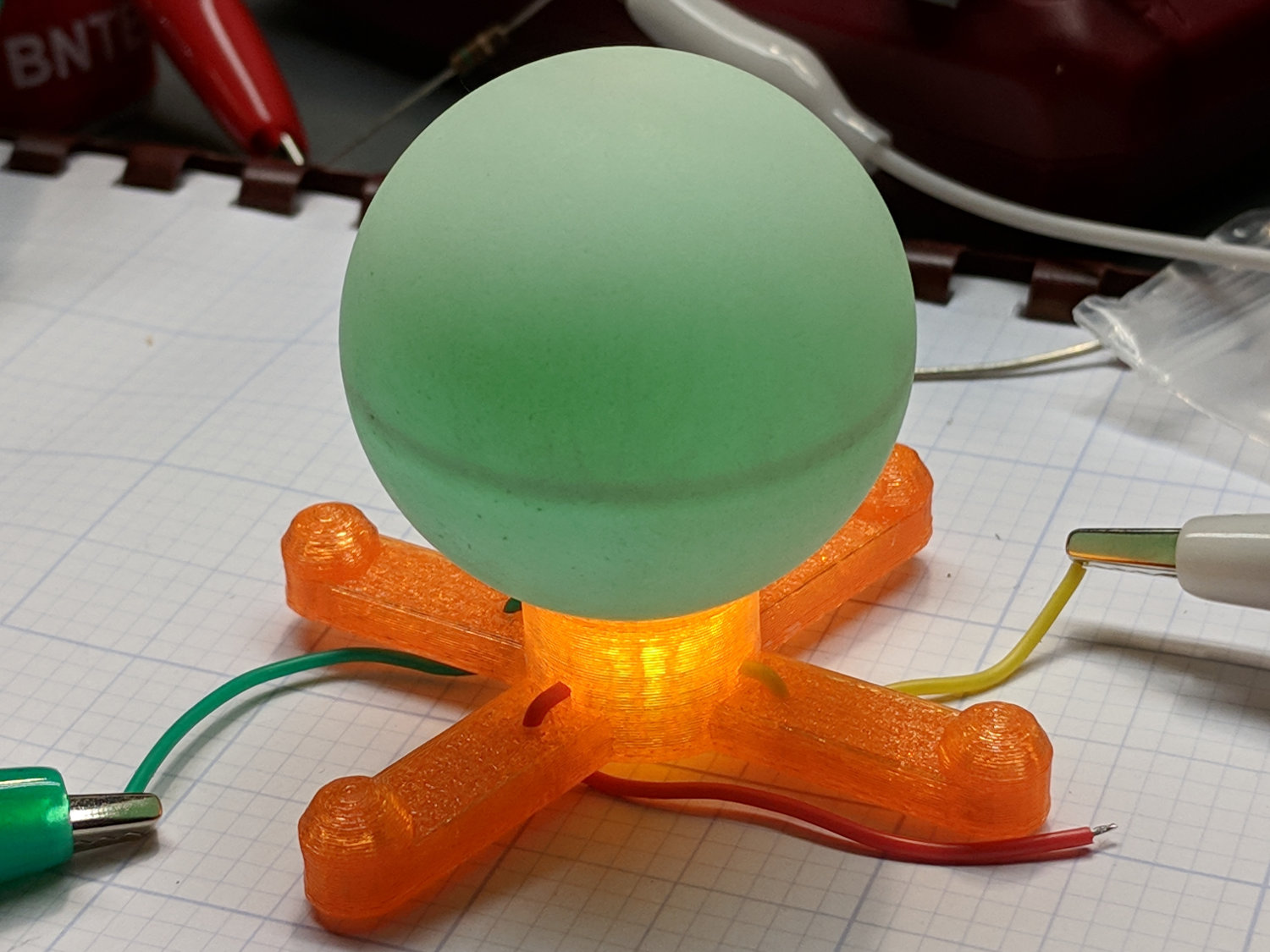
One could argue the LED spider has an unusually large abdomen, but I’m not going there.
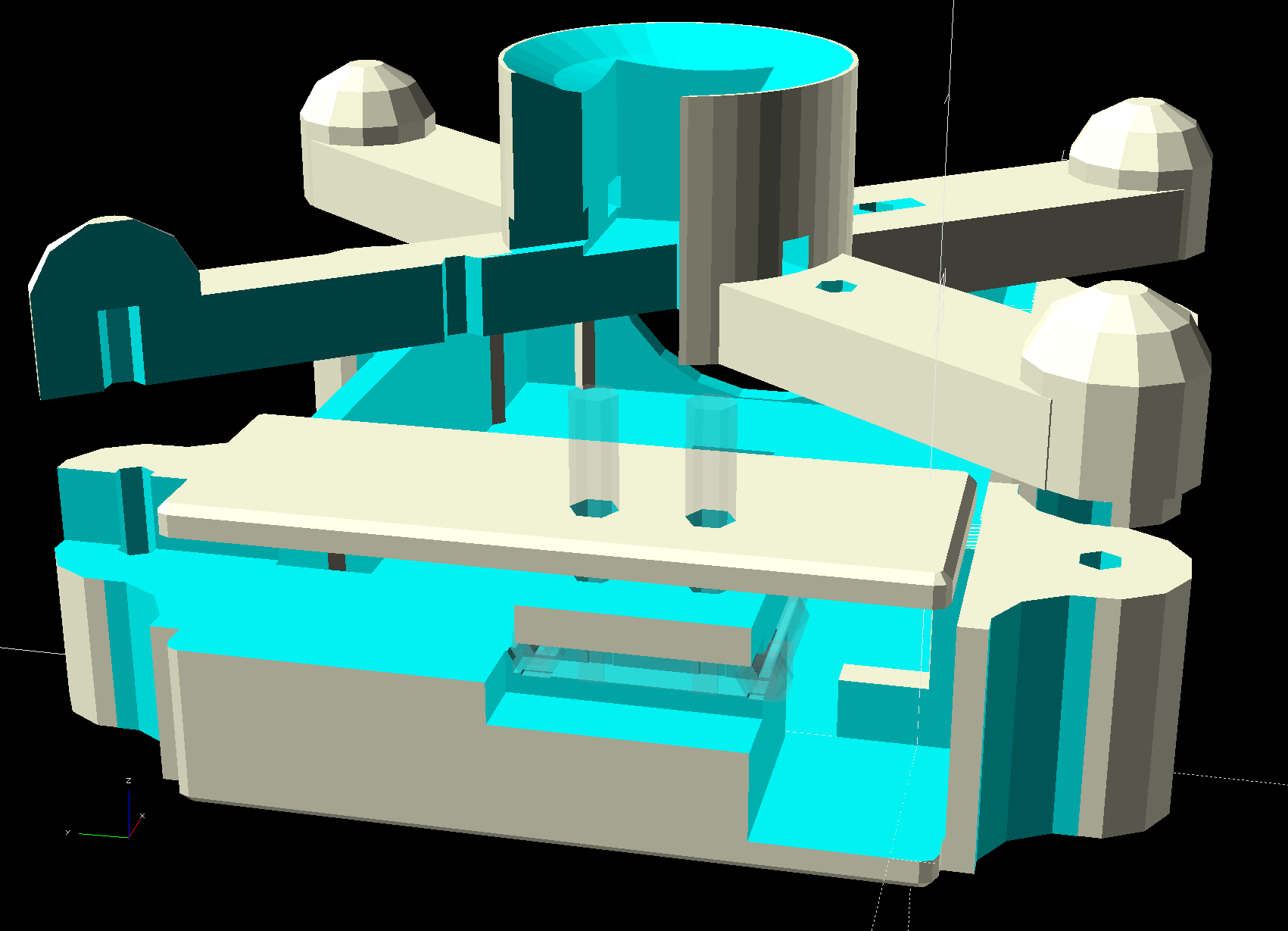
The solid model looks the same way:

And, yes, those are eye protection caps over the four wire struts, most useful during construction while maneuvering the radome into position.
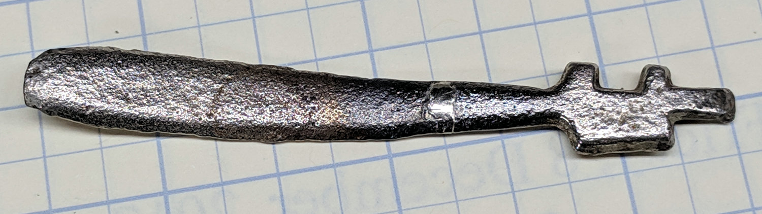
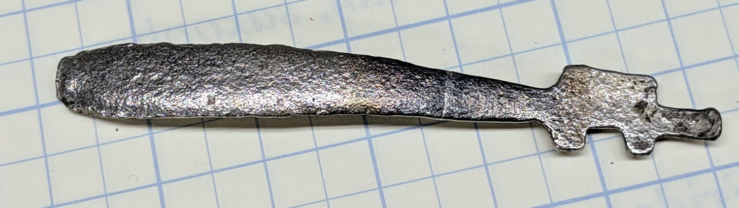
For reasons unknown to me, they’re called “Pirhana” LEDs:
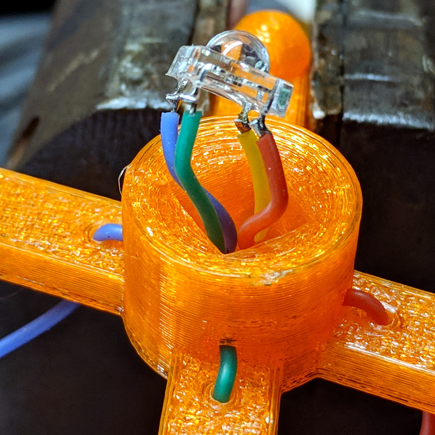
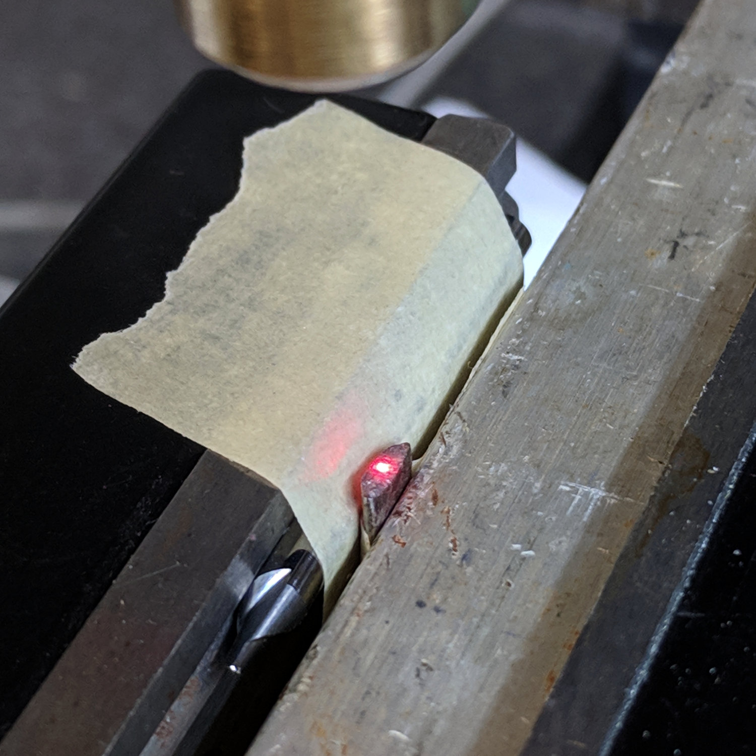
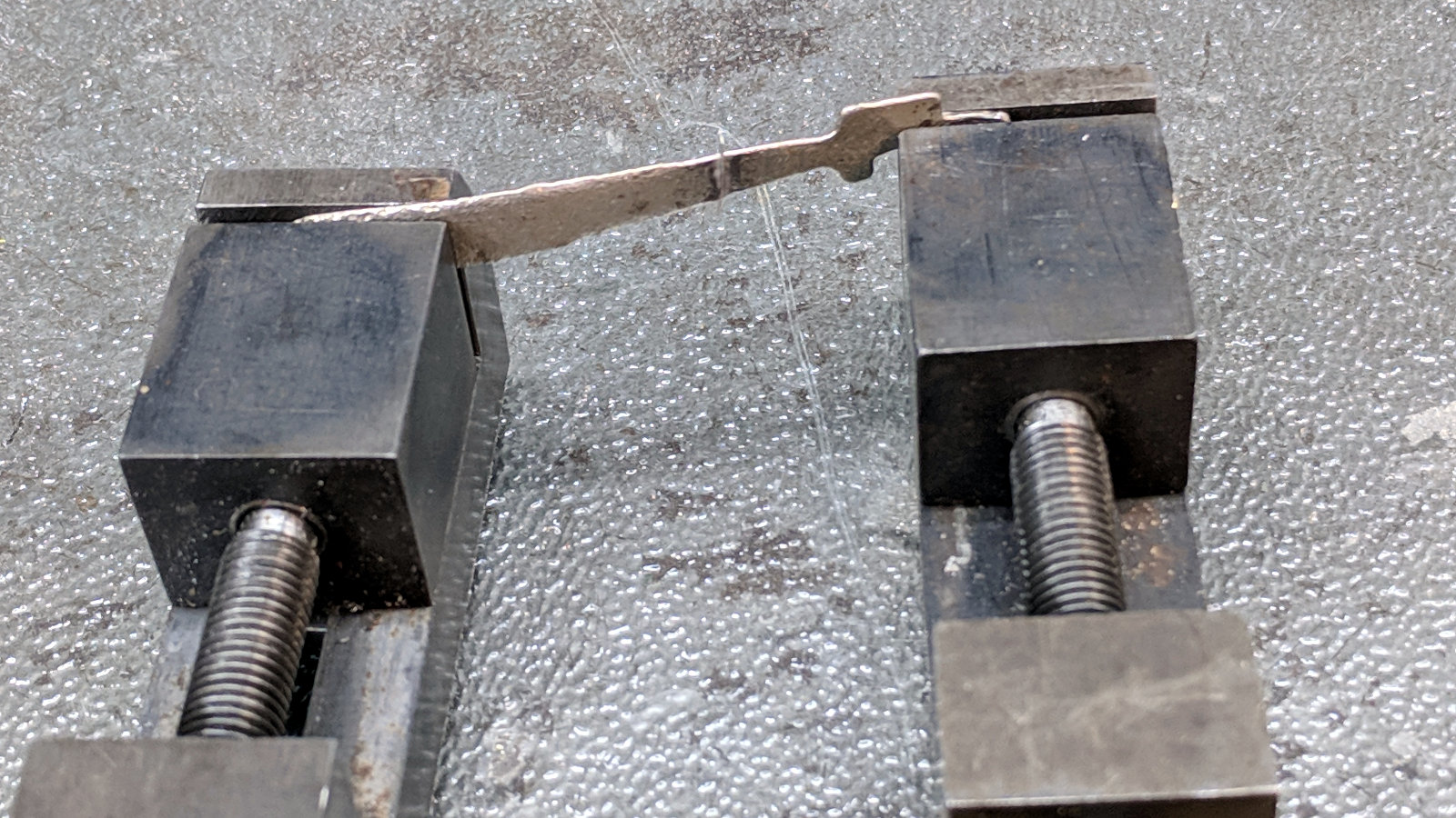
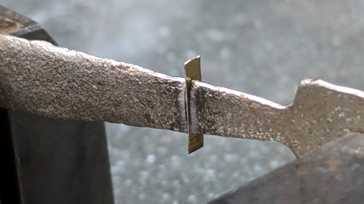
I trimmed off half of each pin, soldered on 28 AWG color-coded silicone wires, threaded wires through openings, then rammed the LED package into the recess so it sits just below the radome’s curve. The dent matching the ball comes from the chord equation, as always, and looks pretty good.
The radome is, of course, a one-star ping pong ball from the usual big box retailer’s sporting goods section. The stamped logo sits at a random position with respect to the ball’s interior structure (visible when lit, as in the top picture), so I erased it with a fine-grit sanding sponge. Hollow plastic golf balls might work just as well, with an even more interesting surface texture.
The source code includes a cutaway look at the printed parts to verify their innards:
The OpenSCAD source code as a GitHub Gist:
| // Holder for Li-Ion battery packs | |
| // Ed Nisley KE4ZNU January 2013 | |
| // 2018-11-15 Adapted for 1.5 mm pogo pins, battery data table | |
| // 2018-12 RGB LED spider, general cleanups | |
| /* [Layout options] */ | |
| BatteryName = "NP-BX1"; // [NP-BX1,NB-5L,NB-6L] | |
| RGBCircuit = true; // false = 1 strut pair, true = 2 pairs | |
| Layout = "Case"; // [Build,Show,Fit,Case,Lid,Pins,RGBSpider] | |
| /* [Extrusion parameters] – must match reality! */ | |
| // Print with +2 shells and 3 solid layers | |
| ThreadThick = 0.25; | |
| ThreadWidth = 0.40; | |
| HoleWindage = 0.2; | |
| function IntegerMultiple(Size,Unit) = Unit * ceil(Size / Unit); | |
| function IntegerLessMultiple(Size,Unit) = Unit * floor(Size / Unit); | |
| Protrusion = 0.1; // make holes end cleanly | |
| /* [Hidden] */ | |
| inch = 25.4; | |
| BuildOffset = 3.0; // clearance for build layout | |
| Gap = 2.0; // separation for Fit parts | |
| //- Basic dimensions | |
| WallThick = 4*ThreadWidth; // holder sidewalls | |
| BaseThick = 6*ThreadThick; // bottom of holder to bottom of battery | |
| TopThick = 6*ThreadThick; // top of battery to top of holder | |
| //- Battery dimensions – rationalized from several samples | |
| // Coordinate origin at battery corner with contacts, key openings downward | |
| T_NAME = 0; // Name must fit recess, so don't get loquacious | |
| T_SIZE = 1; | |
| T_CONTACTS = 2; | |
| T_KEYS = 3; | |
| BatteryData = [ | |
| ["NP-BX1",[43.0,30.0,9.5],[[-0.75,6.0,6.2],[-0.75,16.0,6.2]],[[1.70,3.70,2.90],[1.70,3.60,2.90]]], | |
| ["NB-5L", [45.0,32.0,8.0],[[-0.82,4.5,3.5],[-0.82,11.0,3.5]],[[2.2,0.75,2.0],[2.2,2.8,2.0]]], | |
| ["NB-6L",[42.5,35.5,7.0],[[-0.85,5.50,3.05],[-0.85,11.90,3.05]],[[2.0,0.70,2.8],[2.0,2.00,2.8]]], | |
| ]; | |
| echo(str("Battery: ",BatteryName)); | |
| BatteryIndex = search([BatteryName],BatteryData,1,0)[0]; | |
| echo(str(" Index: ",BatteryIndex)); | |
| BatterySize = BatteryData[BatteryIndex][T_SIZE]; // X = length, Y = width, Z = thickness | |
| echo(str(" Size: ",BatterySize)); | |
| Contacts = BatteryData[BatteryIndex][T_CONTACTS]; // relative to battery edge, front, and bottom | |
| echo(str(" Contacts: ",Contacts)); | |
| ContactOC = Contacts[1].y – Contacts[0].y; // + and – terminals for pogo pin contacts | |
| ContactCenter = Contacts[0].y + ContactOC/2; | |
| KeyBlocks = BatteryData[BatteryIndex][T_KEYS]; // recesses in battery face set X position | |
| echo(str(" Keys: ",KeyBlocks)); | |
| //- Pin dimensions | |
| ID = 0; | |
| OD = 1; | |
| LENGTH = 2; | |
| PinShank = [1.5,2.0,6.5]; // shank, flange, compressed length | |
| PinFlange = [1.5,2.0,0.5]; // flange, length included in PinShank | |
| PinTip = [0.9,0.9,2.5]; // extended spring-loaded tip | |
| WireOD = 1.7; // wiring from pins to circuitry | |
| PinChannel = WireOD; // cut behind flange for solder overflow | |
| PinRecess = 3.0; // recess behind pin flange end for epoxy fill | |
| echo(str("Contact tip dia: ",PinTip[OD])); | |
| echo(str(" .. shank dia: ",PinShank[ID])); | |
| OverTravel = 0.5; // space beyond battery face at X origin | |
| //- Holder dimensions | |
| GuideRadius = ThreadWidth; // friction fit ridges | |
| GuideOffset = 7; // from compartment corners | |
| LidOverhang = 2.0; // atop of battery for retention | |
| LidClearance = LidOverhang * (BatterySize.z/BatterySize.x); // … clearance above battery for tilting | |
| echo(str("Lid clearance: ",LidClearance)); | |
| CaseSize = [BatterySize.x + PinShank[LENGTH] + OverTravel + PinRecess + GuideRadius + WallThick, | |
| BatterySize.y + 2*WallThick + 2*GuideRadius, | |
| BatterySize.z + BaseThick + TopThick + LidClearance]; | |
| echo(str("Case size: ",CaseSize)); | |
| CaseOffset = [-(PinShank[LENGTH] + OverTravel + PinRecess),-(WallThick + GuideRadius),0]; // position around battery | |
| ThumbRadius = 10.0; // thumb opening at end of battery | |
| CornerRadius = 3*ThreadThick; // nice corner rounding | |
| LidSize = [-CaseOffset.x + LidOverhang,CaseSize.y,TopThick]; | |
| LidOffset = [0.0,CaseOffset.y,0]; | |
| //- Wire struts | |
| StrutDia = 1.6; // AWG 14 = 1.6 mm | |
| StrutSides = 3*4; | |
| StrutBase = [StrutDia,StrutDia + 4*WallThick,CaseSize.z – TopThick]; // ID = wire, OD = buildable | |
| //StrutOC = [IntegerLessMultiple(BatterySize.x – StrutBase[OD],5.0), // set easy OC wire spacing | |
| // IntegerMultiple(CaseSize.y + StrutBase[OD],5.0)]; | |
| StrutOC = [IntegerLessMultiple(CaseSize.x – 2*CornerRadius -2*StrutBase[OD],5.0), | |
| IntegerMultiple(CaseSize.y + StrutBase[OD],5.0)]; | |
| StrutOffset = [CaseSize.x/2 + CaseOffset.x,BatterySize.y/2]; // from case centerlines | |
| StrutAngle = atan(StrutOC.y/StrutOC.x); | |
| echo(str("Strut OC: ",StrutOC)); | |
| //- RGB LED | |
| RGBBody = [8.0,8.0,5.0]; // Z = body height | |
| RGBPin = 5.0; // pin length | |
| RGBPinsOC = [5.0,5.0]; // pin layout | |
| RGBRecess = RGBBody.z + RGBPin/2; // maximum LED recess depth | |
| BallOD = 40.0; // radome sphere | |
| BallSides = 4*StrutSides; // nice number of sides | |
| BallPillar = [norm([RGBBody.x,RGBBody.y]), | |
| norm([RGBBody.x,RGBBody.y]) + 4*WallThick, | |
| StrutBase[OD] + RGBBody.z]; | |
| BallChordM = BallOD/2 – sqrt(pow(BallOD/2,2) – (pow(BallPillar[OD],2))/4); | |
| echo(str("Ball chord depth: ",BallChordM)); | |
| //———————- | |
| // Useful routines | |
| module PolyCyl(Dia,Height,ForceSides=0) { // based on nophead's polyholes | |
| Sides = (ForceSides != 0) ? ForceSides : (ceil(Dia) + 2); | |
| FixDia = Dia / cos(180/Sides); | |
| cylinder(r=(FixDia + HoleWindage)/2,h=Height,$fn=Sides); | |
| } | |
| //——————- | |
| //– Guides for tighter friction fit | |
| module Guides() { | |
| translate([GuideOffset,-GuideRadius,0]) | |
| PolyCyl(2*GuideRadius,(BatterySize.z – Protrusion),4); | |
| translate([GuideOffset,(BatterySize.y + GuideRadius),0]) | |
| PolyCyl(2*GuideRadius,(BatterySize.z – Protrusion),4); | |
| translate([(BatterySize.x – GuideOffset),-GuideRadius,0]) | |
| PolyCyl(2*GuideRadius,(BatterySize.z – Protrusion),4); | |
| translate([(BatterySize.x – GuideOffset),(BatterySize.y + GuideRadius),0]) | |
| PolyCyl(2*GuideRadius,(BatterySize.z – Protrusion),4); | |
| translate([(BatterySize.x + GuideRadius),GuideOffset/2,0]) | |
| PolyCyl(2*GuideRadius,(BatterySize.z – Protrusion),4); | |
| translate([(BatterySize.x + GuideRadius),(BatterySize.y – GuideOffset/2),0]) | |
| PolyCyl(2*GuideRadius,(BatterySize.z – Protrusion),4); | |
| } | |
| //– Contact pins | |
| // Rotated to put them in their natural oriention | |
| // Aligned to put tip base / end of shank at Overtravel limit | |
| module PinShape() { | |
| translate([-(PinShank[LENGTH] + OverTravel),0,0]) | |
| rotate([0,90,0]) | |
| rotate(180/6) | |
| union() { | |
| PolyCyl(PinTip[OD],PinShank[LENGTH] + PinTip[LENGTH],6); | |
| PolyCyl(PinShank[ID],PinShank[LENGTH] + Protrusion,6); // slight extension for clean cuts | |
| PolyCyl(PinFlange[OD],PinFlange[LENGTH],6); | |
| } | |
| } | |
| // Position pins to put end of shank at battery face | |
| // Does not include recess access into case | |
| module PinAssembly() { | |
| union() { | |
| for (p = Contacts) | |
| translate([0,p.y,p.z]) | |
| PinShape(); | |
| translate([-(PinShank[LENGTH] + OverTravel) + PinChannel/2, // solder space | |
| ContactCenter, | |
| Contacts[0].z]) | |
| cube([PinChannel, | |
| (Contacts[1].y – Contacts[0].y + PinFlange[OD]), | |
| PinFlange[OD]],center=true); | |
| for (j=[-1,1]) // wire channels | |
| translate([-(PinShank[LENGTH] + OverTravel – PinChannel/2), | |
| j*ContactOC/4 + ContactCenter, | |
| Contacts[0].z – PinFlange[OD]/2]) | |
| rotate(180/6) | |
| PolyCyl(WireOD,CaseSize.z,6); | |
| } | |
| } | |
| //– Case with origin at battery corner | |
| module Case() { | |
| difference() { | |
| union() { | |
| difference() { | |
| union() { | |
| translate([(CaseSize.x/2 + CaseOffset.x), // basic case shape | |
| (CaseSize.y/2 + CaseOffset.y), | |
| (CaseSize.z/2 – BaseThick)]) | |
| hull() | |
| for (i=[-1,1], j=[-1,1], k=[-1,1]) | |
| translate([i*(CaseSize.x/2 – CornerRadius), | |
| j*(CaseSize.y/2 – CornerRadius), | |
| k*(CaseSize.z/2 – CornerRadius)]) | |
| sphere(r=CornerRadius/cos(180/8),$fn=8); // cos() fixes undersize spheres! | |
| for (i= RGBCircuit ? [-1,1] : -1) { // strut bases | |
| hull() | |
| for (j=[-1,1]) | |
| translate([i*StrutOC.x/2 + StrutOffset.x,j*StrutOC.y/2 + StrutOffset.y,-BaseThick]) | |
| rotate(180/StrutSides) | |
| cylinder(d=StrutBase[OD],h=StrutBase[LENGTH],$fn=StrutSides); | |
| translate([i*StrutOC.x/2 + StrutOffset.x,StrutOffset.y,StrutBase[LENGTH]/2 – BaseThick]) | |
| cube([2*StrutBase[OD],StrutOC.y,StrutBase[LENGTH]],center=true); // blocks for fairing | |
| for (j=[-1,1]) // hemisphere caps | |
| translate([i*StrutOC.x/2 + StrutOffset.x, | |
| j*StrutOC.y/2 + StrutOffset.y, | |
| StrutBase[LENGTH] – BaseThick]) | |
| rotate(180/StrutSides) | |
| sphere(d=StrutBase[OD]/cos(180/StrutSides),$fn=StrutSides); | |
| } | |
| } | |
| translate([-OverTravel,-GuideRadius,0]) | |
| cube([(BatterySize.x + GuideRadius + OverTravel), | |
| (BatterySize.y + 2*GuideRadius), | |
| (BatterySize.z + LidClearance + Protrusion)]); // battery space | |
| translate([BatterySize.x/2,BatterySize.y/2,0]) // recess around battery name | |
| cube([0.8*BatterySize.x,8,2*ThreadThick],center=true); | |
| } | |
| Guides(); // improve friction fit | |
| translate([-OverTravel,-GuideRadius,0]) // battery keying blocks | |
| cube(KeyBlocks[0] + [OverTravel,GuideRadius,0],center=false); | |
| translate([-OverTravel,(BatterySize.y – KeyBlocks[1].y),0]) | |
| cube(KeyBlocks[1] + [OverTravel,GuideRadius,0],center=false); | |
| translate([BatterySize.x/2,BatterySize.y/2,-ThreadThick]) // battery name! | |
| linear_extrude(height=2*ThreadThick,convexity=10) | |
| text(text=BatteryName,size=5,spacing=1.20,font="Arial:style:Bold",halign="center",valign="center"); | |
| } | |
| translate([2*CaseOffset.x, // battery top access | |
| (CaseOffset.y – Protrusion), | |
| BatterySize.z + LidClearance]) | |
| cube([2*CaseSize.x,(CaseSize.y + 2*Protrusion),2*TopThick]); | |
| for (i2 = RGBCircuit ? [-1,1] : -1) { // strut wire holes and fairing | |
| for (j=[-1,1]) | |
| translate([i2*StrutOC.x/2 + StrutOffset.x,j*StrutOC.y/2 + StrutOffset.y,0]) | |
| rotate(180/StrutSides) | |
| PolyCyl(StrutBase[ID],2*StrutBase[LENGTH],StrutSides); | |
| for (i=[-1,1], j=[-1,1]) | |
| translate([i*StrutBase[OD] + (i2*StrutOC.x/2 + StrutOffset.x), | |
| j*StrutOC.y/2 + StrutOffset.y, | |
| -(BaseThick + Protrusion)]) | |
| rotate(180/StrutSides) | |
| PolyCyl(StrutBase[OD],StrutBase[LENGTH] + 2*Protrusion,StrutSides); | |
| } | |
| translate([(BatterySize.x – Protrusion), // remove thumb notch | |
| (CaseSize.y/2 + CaseOffset.y), | |
| (ThumbRadius)]) | |
| rotate([90,0,0]) | |
| rotate([0,90,0]) | |
| cylinder(r=ThumbRadius, | |
| h=(WallThick + GuideRadius + 2*Protrusion), | |
| $fn=22); | |
| PinAssembly(); // pins and wiring | |
| translate([CaseOffset.x + PinRecess + Protrusion,(Contacts[1].y + Contacts[0].y)/2,Contacts[0].z]) | |
| translate([-PinRecess,0,0]) | |
| cube([2*PinRecess, | |
| (Contacts[1].y – Contacts[0].y + PinFlange[OD]/cos(180/6) + 2*HoleWindage), | |
| 2*PinFlange[OD]],center=true); // pin insertion hole | |
| translate([CaseOffset.x/2 + BatterySize.x/2,BatterySize.y/2,-(BaseThick + Protrusion)]) | |
| linear_extrude(height=2*ThreadThick + Protrusion,convexity=10) | |
| mirror([0,1,0]) | |
| text(text="KE4ZNU",size=6,spacing=1.20,font="Arial:style:Bold",halign="center",valign="center"); | |
| } | |
| } | |
| // Lid position offset to match case | |
| module Lid() { | |
| difference() { | |
| translate([-LidSize.x/2 + LidOffset.x + LidOverhang,LidSize.y/2 + LidOffset.y,0]) | |
| difference() { | |
| hull() | |
| for (i=[-1,1], j=[-1,1], k=[-1,1]) | |
| translate([i*(LidSize.x/2 – CornerRadius), | |
| j*(LidSize.y/2 – CornerRadius), | |
| k*(LidSize.z – CornerRadius)]) // double thickness for flat bottom | |
| sphere(r=CornerRadius,$fn=8); | |
| translate([0,0,-LidSize.z/2]) // remove bottom | |
| cube([(LidSize.x + 2*Protrusion),(LidSize.y + 2*Protrusion),LidSize.z],center=true); | |
| translate([LidSize.x/8,0,0]) | |
| cube([LidSize.x/4,0.75*LidSize.y,4*ThreadThick],center=true); // epoxy recess | |
| } | |
| translate([0,0,-(Contacts[0].z + PinFlange[OD])]) // punch wire holes | |
| PinAssembly(); | |
| } | |
| } | |
| // Spider for RGB LED + radome atop vertical struts | |
| module RGBSpider() { | |
| difference() { | |
| union() { | |
| for (i=[-1,1], j=[-1,1]) { | |
| translate([i*StrutOC.x/2,j*StrutOC.y/2,StrutBase[OD]/2]) | |
| rotate(180/StrutSides) // doesn't quite match crosspieces; close enough | |
| sphere(d=StrutBase[OD]/cos(180/StrutSides),$fn=StrutSides); | |
| translate([i*StrutOC.x/2,j*StrutOC.y/2,0]) | |
| rotate(180/StrutSides) | |
| cylinder(d=StrutBase[OD],h=StrutBase[OD]/2,$fn=StrutSides); | |
| } | |
| for (m=[-1,1]) // connecting bars | |
| rotate(m*StrutAngle) | |
| translate([0,0,StrutBase[OD]/4]) | |
| cube([norm(StrutOC),StrutBase[OD],StrutBase[OD]/2],center=true); | |
| translate([0,0,0]) // pillar for RGB LED and ball | |
| cylinder(d=BallPillar[OD],h=BallPillar[LENGTH],$fn=BallSides); | |
| } | |
| for (i=[-1,1], j=[-1,1]) // strut wires | |
| translate([i*StrutOC.x/2,j*StrutOC.y/2,-Protrusion]) | |
| rotate(0) | |
| PolyCyl(StrutBase[ID],StrutBase[OD]/2,6); | |
| for (m=[-1,1], n=[0,1]) // RGBA wires through bars | |
| rotate(m*StrutAngle + n*180) | |
| translate([StrutOC.x/3,0,-Protrusion]) | |
| PolyCyl(StrutBase[ID],StrutBase[OD],6); | |
| # translate([0,0,BallOD/2 + BallPillar[LENGTH] – BallChordM]) // ball inset | |
| sphere(d=BallOD); | |
| translate([0,0,2*RGBBody.z + (BallPillar[LENGTH] – BallChordM) – RGBRecess]) // LED inset | |
| cube(RGBBody + [HoleWindage,HoleWindage,3*RGBBody.z],center=true); // XY clearance + huge height for E-Z cut | |
| for (m=[-1,1]) // RGBA wires through pillar | |
| rotate(m*StrutAngle) | |
| translate([0,0,StrutBase[OD]/2 + WireOD/2 + 0*Protrusion]) | |
| cube([norm(StrutOC)/2,WireOD,WireOD],center=true); | |
| } | |
| } | |
| //——————- | |
| // Build it! | |
| if (Layout == "Case") | |
| Case(); | |
| if (Layout == "Lid") | |
| Lid(); | |
| if (Layout == "RGBSpider") { | |
| RGBSpider(); | |
| } | |
| if (Layout == "Pins") { | |
| color("Silver",0.5) | |
| PinShape(); | |
| PinAssembly(); | |
| } | |
| if (Layout == "Show") { // reveal pin assembly | |
| difference() { | |
| Case(); | |
| translate([(CaseOffset.x – Protrusion), | |
| Contacts[1].y, | |
| Contacts[1].z]) | |
| cube([(-CaseOffset.x + Protrusion),CaseSize.y,CaseSize.z]); | |
| translate([(CaseOffset.x – Protrusion), | |
| (CaseOffset.y – Protrusion), | |
| 0]) | |
| cube([(-CaseOffset.x + Protrusion), | |
| Contacts[0].y + Protrusion – CaseOffset.y, | |
| CaseSize.z]); | |
| } | |
| translate([0,0,BatterySize.z + Gap]) | |
| Lid(); | |
| color("Silver",0.15) | |
| PinAssembly(); | |
| if (RGBCircuit) | |
| translate([StrutOC.x/2,BatterySize.y/2,2*BatterySize.z]) | |
| difference() { | |
| RGBSpider(); | |
| rotate(180-StrutAngle) | |
| translate([0,0,-Protrusion]) | |
| cube([norm(StrutOC),StrutBase[OD],2*BallPillar.z],center=false); | |
| } | |
| } | |
| if (Layout == "Build") { | |
| translate([-BatterySize.x/2,-BatterySize.y/2,BaseThick]) | |
| Case(); | |
| translate([-CaseSize.x + LidSize.x,-(LidSize.y/2 + LidOffset.y),0]) | |
| Lid(); | |
| if (RGBCircuit) | |
| translate([StrutOC.x + BatterySize.x/2,0,0]) | |
| RGBSpider(); | |
| } | |
| if (Layout == "Fit") { | |
| Case(); | |
| translate([0,0,(BatterySize.z + Gap)]) | |
| Lid(); | |
| color("Silver",0.25) | |
| PinAssembly(); | |
| if (RGBCircuit) | |
| translate([StrutOC.x/2,BatterySize.y/2,2*BatterySize.z]) | |
| RGBSpider(); | |
| } | |
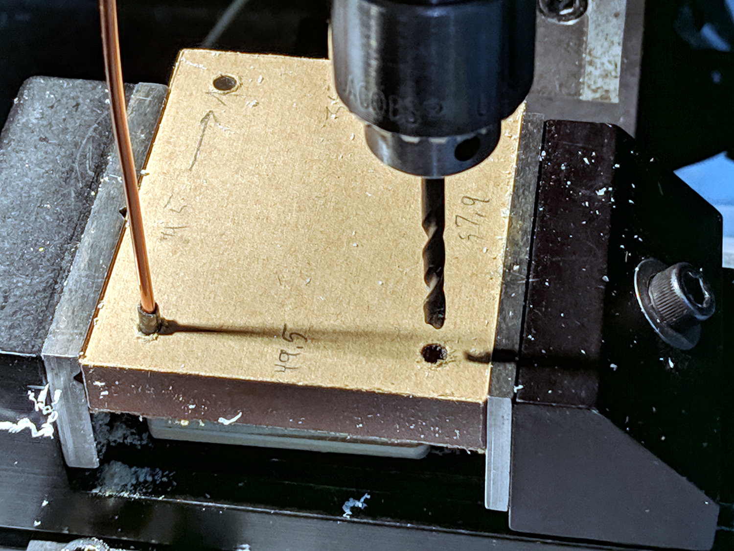
The original doodles give useful dimensions, plus some details not withstanding the test of time:
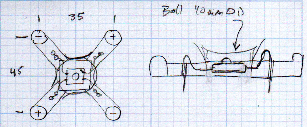
The actual center-to-center distances for the wire posts come from the battery dimensions, rounded up or down as appropriate, to the nearest multiple of 5 mm, so those are just serving suggestions.