The Smell of Molten Projects in the Morning

Ed Nisley's Blog: Shop notes, electronics, firmware, machinery, 3D printing, laser cuttery, and curiosities. Contents: 100% human thinking, 0% AI slop.

Category: Machine Shop

Mechanical widgetry

  • Shower Curtain Magnet Anchors

    Back in the day, bathtubs had a porcelain coating over a cast-iron carcass, so embedding little magnets in shower curtains worked perfectly to keep the loose ends from billowing out of the tub. Surprisingly, even here in the future, with plastic bathtubs ruling the land, some shower curtains still have magnets. The mud-job tile walls of shower stall in the Black Bathroom have nary a trace of iron, but we though I could add ferrous targets for a new shower curtain, thusly:

    Shower Curtain Anchor - installed
    Shower Curtain Anchor – installed

    The magnet lives inside a heat-sealed disk, so it’s (more-or-less) isolated from the water. As you’d expect, it’s a cheap ceramic magnet, not a high-performance neodymium super magnet, with no more strength than absolutely necessary to work under the most ideal of conditions.

    My anchors must also be waterproof, firmly attached, non-marking, easily removable, and no more ugly than absolutely necessary. The general idea is to slice the bottom from a pill bottle, entomb a thin steel disk in epoxy, and attach to the tile with a patch of outdoor-rated foam tape.

    So, we begin …

    Cutting a narrow ring from a pill bottle requires a collet around the whole circumference, which started life as some sort of stout aluminum pole:

    Shower Curtain Anchor - cutting tube stock
    Shower Curtain Anchor – cutting tube stock

    Bore out the inside, with a small step to locate the bottle:

    Shower Curtain Anchor - boring fixture
    Shower Curtain Anchor – boring fixture

    Clean up the outside, just for pretty:

    Shower Curtain Anchor - turning fixture OD
    Shower Curtain Anchor – turning fixture OD

    Slit the fixture to let it collapse around the bottle, then chuck up the first victim with support from a conveniently sized drill chuck in the tailstock:

    Shower Curtain Anchor - cutting bottle
    Shower Curtain Anchor – cutting bottle

    I did a better job of cutting the second bottle to the proper length:

    Shower Curtain Anchor - parting base
    Shower Curtain Anchor – parting base

    Nibble disks from sheet metal, half-fill the bottle bottoms with steel-filled (and, thus, magnetic!) JB Weld epoxy, insert disks, add sufficient epoxy to cover the evidence:

    Shower Curtain Anchor - epoxy curing
    Shower Curtain Anchor – epoxy curing

    Fast-forward to the next day, punch out two disks of double-sided foam tape:

    Shower Curtain Anchor - adhesive foam
    Shower Curtain Anchor – adhesive foam

    Affix, install, and it’s all good.

    Actually, it’s not. The ceramic magnets are so weak they don’t hold the curtain nearly well enough to satisfy me. The next anchor iteration should have embedded neodymium magnets to attract the curtain’s crappy ceramic magnets, but this is Good Enough™ for now.

  • HP 7475A Plotter: Ceramic-Tip Pen EOL

    Ceramic-tip plotter pens draw wonderfully crisp lines:

    Spirograph pattern - black ceramic pen - detail
    Spirograph pattern – black ceramic pen – detail

    Eventually, though, the fiber tip wears flush with the ceramic shell, becomes slightly indented, and ceases to make its mark in the world:

    HP 7475A Plotter - Ceramic pen - worn tip
    HP 7475A Plotter – Ceramic pen – worn tip

    As the lady says, “Starting from zero, got nothing to lose”, so I applied a fine diamond file around the tip:

    HP 7475A Plotter - Ceramic pen - filed tip
    HP 7475A Plotter – Ceramic pen – filed tip

    Well, all I can say is it seemed like a good idea at the time.

    Alas, even the newly exposed fiber didn’t make much of a mark on the paper and, as you’d expect, the ragged ceramic tip dragged painfully across the paper. I assume the fiber had filled with fossilized dry ink.

    A New Old Stock bag of fiber-tip pens emerged from the Big Box o’ Pens while I was flailing around:

    HP 7475A Plotter - NOS Green pen package
    HP 7475A Plotter – NOS Green pen package

    I think the “812” in the lower right corner is a date code, most likely early in 1988, so the pens started their lifetime countdown at least three decades ago. They still work, though:

    HP 7475A Plotter - NOS Green pens
    HP 7475A Plotter – NOS Green pens

    The plotter appeared at HV Open’s Mad Science Fair, because everybody loves a plotter!

  • Kinesis Freestyle 2: Steel Tactile Bumps

    Adding tape bumps to the worn Kinesis keyboard demonstrated I really need tactile home keys, so I popped the tops and fired up the Sherline mill:

    Kinesis keyboard - 2 mm drilling
    Kinesis keyboard – 2 mm drilling

    That’s a genuine 2 mm carbide end mill, poked 1 mm into the key cap, snuggled right up against the front edge.

    Two epoxy dabs and some wiping later:

    Kinesis keyboard - 2 mm tactile bearings
    Kinesis keyboard – 2 mm tactile bearings

    The careful alignment on the F key tells you I did it first; obviously, I should make better fixtures.

    The holes could be slightly larger and maybe slightly deeper, but the bearings feel just right.

    Indeed, they work so well a ball now distinguishes the far-flung Delete and Backspace keys:

    Kinesis keyboard - 2 mm bearing - Delete key
    Kinesis keyboard – 2 mm bearing – Delete key

    Now, to see how long the epoxy lasts …

  • Mini-Lathe Cut-Off Tool Holder: Improved Clamp Screw

    Apparently all mini-lathe cutoff tool holders suffer from the same problem:

    Lathe Cutoff Tool - OEM swaged screw
    Lathe Cutoff Tool – OEM swaged screw

    The clamp tightening screw is made from butter-soft Chinese steel with a swaged hex socket. As you’d expect, the hex wrench eventually (as in, after a few dozen adjustments, tops) rips the guts right out of the socket.

    The screw has a M6×1.0 mm threads, but the thread around the hex recess is left-handed. While I could, in principle, print a 127 tooth change gear, rebuild the lathe’s banjo to accommodate it, then single-point a backassward M6 thread, it’s easier to just use a standard socket head cap screw:

    Lathe Cutoff Tool - rebuilt screw
    Lathe Cutoff Tool – rebuilt screw

    The clamp screw passes through the block at an angle:

    Lathe Cutoff Tool - blade view
    Lathe Cutoff Tool – blade view

    Fortunately, the screw is perpendicular to the angled side over on the left, making it easy to clamp in the Sherline’s vise:

    Lathe Cutoff Tool - aligning to screw
    Lathe Cutoff Tool – aligning to screw

    Using the laser aligner seemed like a good idea at the time, but the top of the screw wasn’t particularly well-centered on the hole’s axis. I couldn’t screw the left-hand part (with the socket) in from the bottom and center the block near its surface, because then I couldn’t extract the screw before proceeding.

    I used a diamond burr to grind out a flat for the screw head:

    Lathe Cutoff Tool - clearing screw recess
    Lathe Cutoff Tool – clearing screw recess

    The flat came from about twenty manual G2 I-2.5 full-circle passes, stepping down through the hard steel block 0.1 mm per pass, at a too-slow 4000 RPM and a too-fast 30 mm/min feed, with plenty of water squirted from one side into a shop vac snout on the other. The doodle in the background of the first picture shows a first pass at the layout, with the burr centered at X=-2.5; I actually did the grinding from X=+2.5 so most of the passes started in thin air.

    The screw head started just shy of 10 mm OD and the burr just over 5.2 mm, so the ensuing 5 mm circles created a flat barely large enough. If the flat were perfectly centered on the screw axis, I wouldn’t have had to grind out another millimeter on the left side (toward the bottom of the tool holder body), but it worked out OK:

    Lathe Cutoff Tool - 6 mm SHCS test fit
    Lathe Cutoff Tool – 6 mm SHCS test fit

    The trial fitting also showed the head stuck out ever so slightly beyond the far side of the block, where it would interfere with the blade, so I turned off 0.4 mm off its OD.

    If I had a 50 mm SHCS in hand, I’d have used it. Instead, I extended the threads of a 75 mm screw, then lopped off the end to the proper length. I’ll spare you the ordeal, including the moment when I reached for the cutoff tool to shorten the screw. A bag of such screws will arrive shortly, in preparation for future need.

    Now the [deleted] cut-off holder works the way it should have from the beginning.

  • Mower FOD

    For reasons not relevant here, the lawn mower suffered some Foreign Object Damage:

    Lawn Mower - bent blade mount
    Lawn Mower – bent blade mount

    I’m sure the hard stop loosened the tolerances along the shaft, but the mower fired right up (with that new blade!) and has no more vibration than usual, despite the seriously bent blade mount.

    I no longer have a deep emotional attachment to lawn mowers, which is apparently common, as the label advises me there’s no need to change the oil:

    Mower Engine - never change the oil
    Mower Engine – never change the oil

    Drive it ’til it drops …

  • Step2 Garden Seat: Replacement Seat

    Step2 Garden Seat: Replacement Seat

    A pair of Step2 rolling garden seats (they have a new version) served in Mary’s gardens long enough to give their seat panels precarious cracks:

    Step2 Seat - OEM seat
    Step2 Seat – OEM seat

    The underside was giving way, too:

    Step2 Seat - cracks
    Step2 Seat – cracks

    We agreed the new seat could be much simpler, although it must still hinge upward, so I conjured a pair of hinges from the vasty digital deep:

    Rolling Cart Hinges - solid model - bottom
    Rolling Cart Hinges – solid model – bottom

    The woodpile disgorged a slab of 1/4 inch = 6 mm plywood (used in a defunct project) of just about the right size and we agreed a few holes wouldn’t be a problem for its projected ahem use case:

    Step2 Seat - assembled
    Step2 Seat – assembled

    The screw holes on the hinge tops will let me run machine screws all the way through, should that be necessary. So far, a quartet of self-tapping sheet metal (!) screws are holding firm.

    Rolling Cart Hinges - solid model - top
    Rolling Cart Hinges – solid model – top

    A closer look at the hinges in real life:

    Step2 Seat - top view
    Step2 Seat – top view

    The solid model now caps the holes; I can drill them out should the need arise.

    From the bottom:

    Step2 Seat - bottom view
    Step2 Seat – bottom view

    Three coats of white exterior paint make it blindingly bright in the sun, although we expect a week or two in the garden will knock the shine right off:

    Step2 Seat - painted
    Step2 Seat – painted

    After the first coat, I conjured a drying rack from a bamboo skewer, a cardboard flap, and some hot-melt glue:

    Step2 Seat - drying fixture
    Step2 Seat – drying fixture

    Three small scars on the seat bottom were deemed acceptable.

    The OpenSCAD source code as a GitHub Gist:

    // Hinge brackets for rolling garden stool
    // Ed Nisley – KE4ZNU – 2019-06
    Layout = "Build"; // [Block,Build,Show]
    Support = true;
    /* [Hidden] */
    ThreadThick = 0.20;
    ThreadWidth = 0.40;
    HoleWindage = 0.2;
    Protrusion = 0.1; // make holes end cleanly
    ID = 0;
    OD = 1;
    LENGTH = 2;
    //———————-
    // Dimensions
    SeatThick = 6.0; // seat panel above cart body
    HingePin = [11.5,12.0,7.0]; // ID = tip OD = base
    HingeOffset = 8.0; // hinge axis above cart body (larger than radius!)
    HingeBolster = [5.0,24.0,SeatThick]; // backing block below hinge
    Block = [25.0,HingeOffset + 30.0,23.0]; // Z = above cart body
    Screw = [3.8,11.0,2.5]; // self-tapping #8 OD=head LENGTH=head thickness
    ScrewOC = 15.0; // spacing > greater than head OD
    ScrewOffset = Block.y/2 – (ScrewOC/2 + Screw[OD]/2 + HingeOffset); // space for head behind hinge
    BlockRadius = 7.0; // corner rounding
    //———————-
    // Useful routines
    module PolyCyl(Dia,Height,ForceSides=0) { // based on nophead's polyholes
    Sides = (ForceSides != 0) ? ForceSides : (ceil(Dia) + 2);
    FixDia = Dia / cos(180/Sides);
    cylinder(r=(FixDia + HoleWindage)/2,
    h=Height,
    $fn=Sides);
    }
    // Basic block shape
    // X axis collinear with hinge axes, hinge base at X=0
    module HingeBlock() {
    PinSides = 3*4;
    PinSupport = [HingePin[LENGTH] – 2*ThreadWidth,0.6*HingeOffset,HingePin[OD]]; // pre-rotated
    union() {
    translate([Protrusion,Block.y/2 – HingeOffset,HingeOffset])
    rotate([0,-90,0])
    rotate(180/PinSides)
    cylinder(d=HingePin[OD],h=HingePin[LENGTH] + Protrusion,$fn=PinSides);
    difference() {
    hull() {
    translate([Block.x – BlockRadius,-(Block.y/2 – BlockRadius),Block.z – BlockRadius])
    rotate(180/PinSides)
    sphere(r=BlockRadius/cos(180/PinSides),$fn=PinSides);
    translate([0,-(Block.y/2 – BlockRadius),Block.z – BlockRadius])
    rotate([0,90,0]) rotate(180/PinSides)
    cylinder(r=BlockRadius/cos(180/PinSides),h=Block.x/2,$fn=PinSides);
    translate([Block.x – BlockRadius,(Block.y/2 – BlockRadius),Block.z – BlockRadius])
    sphere(r=BlockRadius/cos(180/PinSides),$fn=PinSides);
    translate([0,(Block.y/2 – BlockRadius),Block.z – BlockRadius])
    rotate([0,90,0]) rotate(180/PinSides)
    cylinder(r=BlockRadius/cos(180/PinSides),h=Block.x/2,$fn=PinSides);
    translate([0,-Block.y/2,0])
    cube([Block.x,Block.y – HingeOffset,Block.z/2],center=false);
    translate([0,Block.y/2 – HingeOffset,HingeOffset])
    rotate([0,90,0]) rotate(180/PinSides)
    cylinder(r=HingeOffset/cos(180/PinSides),h=Block.x,$fn=PinSides);
    }
    translate([Block.x/2 + HingeBolster.x,0,(SeatThick – Protrusion)/2])
    cube([Block.x,2*Block.y,SeatThick + Protrusion],center=true);
    translate([0,-HingeBolster.y,(SeatThick – Protrusion)/2])
    cube([3*Block.x,Block.y,SeatThick + Protrusion],center=true);
    for (j=[-1,1])
    translate([Block.x/2,j*ScrewOC/2 + ScrewOffset,-4*ThreadThick])
    rotate(180/8)
    PolyCyl(Screw[ID],Block.z,8);
    }
    }
    if (Support) { // totally ad-hoc
    color("Yellow") render(convexity=4)
    difference() {
    translate([-(PinSupport.x/2 + 2*ThreadWidth),Block.y/2 – PinSupport.y/2,HingeOffset])
    cube(PinSupport,center=true);
    translate([Protrusion,Block.y/2 – HingeOffset,HingeOffset])
    rotate([0,-90,0])
    rotate(180/PinSides)
    cylinder(d=HingePin[OD] + 2*ThreadThick,h=2*HingePin[LENGTH],$fn=PinSides);
    for (i=[-1:1])
    translate([i*4*ThreadWidth – HingePin[LENGTH]/2,
    Block.y/2 – (PinSupport.y + 1*ThreadThick),
    HingeOffset])
    cube([2*ThreadWidth,2*PinSupport.y,2*PinSupport.z],center=true);
    }
    }
    }
    module Blocks(Hand = "Left") {
    if (Hand == "Left")
    HingeBlock();
    else
    mirror([1,0,0])
    HingeBlock();
    }
    //- Build it
    if (Layout == "Block")
    HingeBlock();
    if (Layout == "Show") {
    translate([1.5*HingePin[LENGTH],0,0])
    Blocks("Left");
    translate([-1.5*HingePin[LENGTH],0,0])
    Blocks("Right");
    }
    if (Layout == "Build") {
    translate([0,-Block.z/2,Block.y/2])
    rotate([-90,0,0]) {
    translate([1.5*HingePin[LENGTH],0,0])
    Blocks("Left");
    translate([-1.5*HingePin[LENGTH],0,0])
    Blocks("Right");
    }
    }

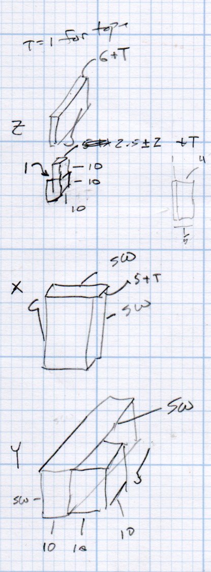
    This original doodle gives the key dimensions, apart from the rounded rear edge required so the seat can pivot vertically upward:

    Cart Hinge - dimension doodle
    Cart Hinge – dimension doodle

    The second seat looks just like this one, so life is good …

  • MPCNC: Calculating Spring Rates

    Calculate the spring rates for the drag knife, diamond engraver, and collet pen holders by measuring the downforce every 0.5 mm (or so):

    LM12UU Collet Pen Holder - spring rate test
    LM12UU Collet Pen Holder – spring rate test

    Then plotting the data points and eyeballing a straight-line curve fit:

    MPCNC - Drag Knife Holder - spring constant
    MPCNC – Drag Knife Holder – spring constant

    Doing it on hard mode definitely has a certain old-school charm. The graph highlights mis-measured data and similar problems, because, if you don’t see a pretty nearly straight line, something’s gone awry.

    But we live in the future, so there’s an easier way:

    Droid48 - Spring Rate - Linear Fit coefficients
    Droid48 – Spring Rate – Linear Fit coefficients

    Well, OK, it’s the future as of the early 1990s, when HP introduced its HP 48 calculators. I’m using the Droid48 emulator on my ancient Google Pixel: living in the past, right here in the future.

    Start by firing up the STAT library (cyan arrow, then the 5 key), selecting Fit Data … from the dropdown list, then selecting the Linear Fit model:

    Droid48 - Spring Rate - Linear Fit screen
    Droid48 – Spring Rate – Linear Fit screen

    Then tap EDIT and enter the data in a tiny spreadsheet:

    Droid48 - Spring Rate - Linear Fit data
    Droid48 – Spring Rate – Linear Fit data

    My default “engineering mode” numeric display format doesn’t show well on the tiny screen. Tapping the WID→ key helps a bit, but shorter numbers would be better.

    With the data entered, set an X value and tap the PRED key to get the corresponding Y value:

    Droid48 - Spring Rate - Linear Fit prediction
    Droid48 – Spring Rate – Linear Fit prediction

    Tapping the OK button puts the line’s coefficients on the stack, as shown in the first picture. Write ’em on a strip of tape, stick to the top of the holder, and it’s all good:

    LM12UU Collet Pen Holder - test plot - overview
    LM12UU Collet Pen Holder – test plot – overview

    Works for me, anyhow.

    HP still has the HP 48g manuals online. The (unofficial) HP Museum has a page on the HP 48S. More than you want to know about the 48 series.