Ed Nisley's Blog: Shop notes, electronics, firmware, machinery, 3D printing, laser cuttery, and curiosities. Contents: 100% human thinking, 0% AI slop.
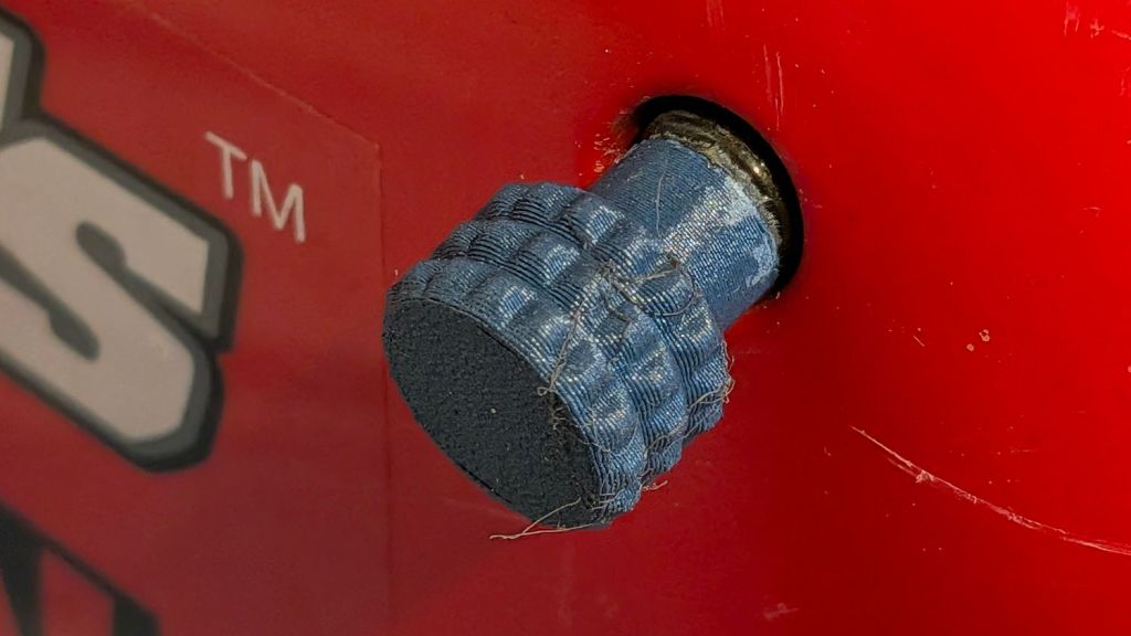
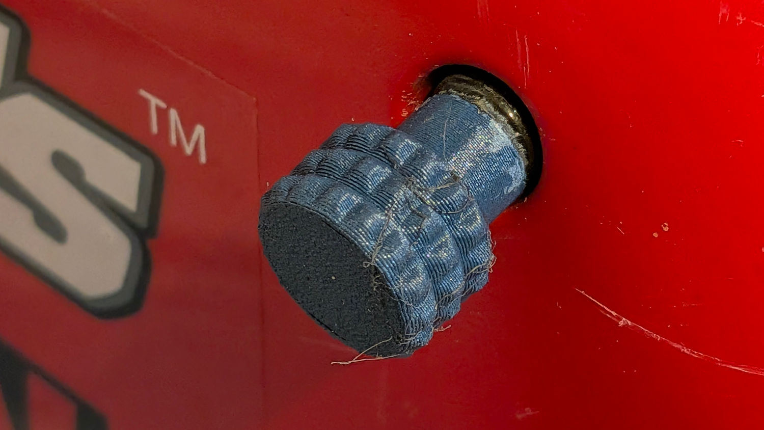
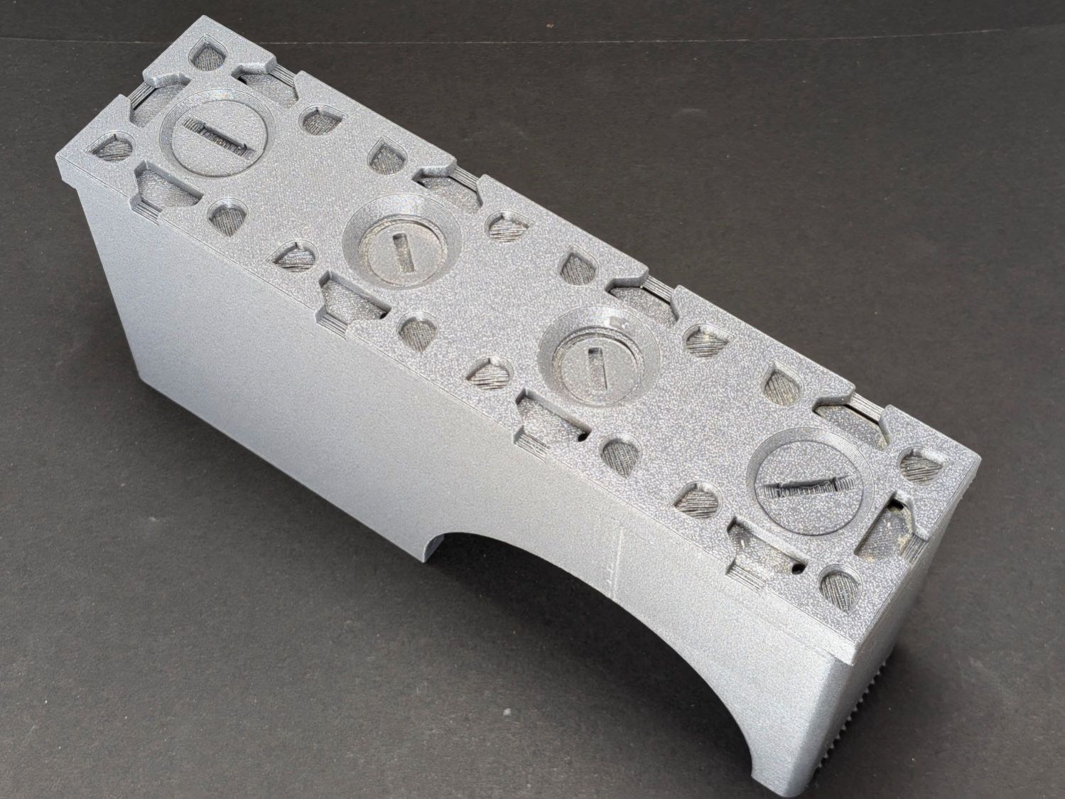
Although I got one of the screws out of the cover while modeling the knob, the other was more firmly implanted and resisted my entreaties.
However, having recently spotted the small tool kit accompanying the generator, should the knobs fall off again, I’ll forcibly remove the screws, put them in the tool bag, and rely on the snaps to hold the cover in place.
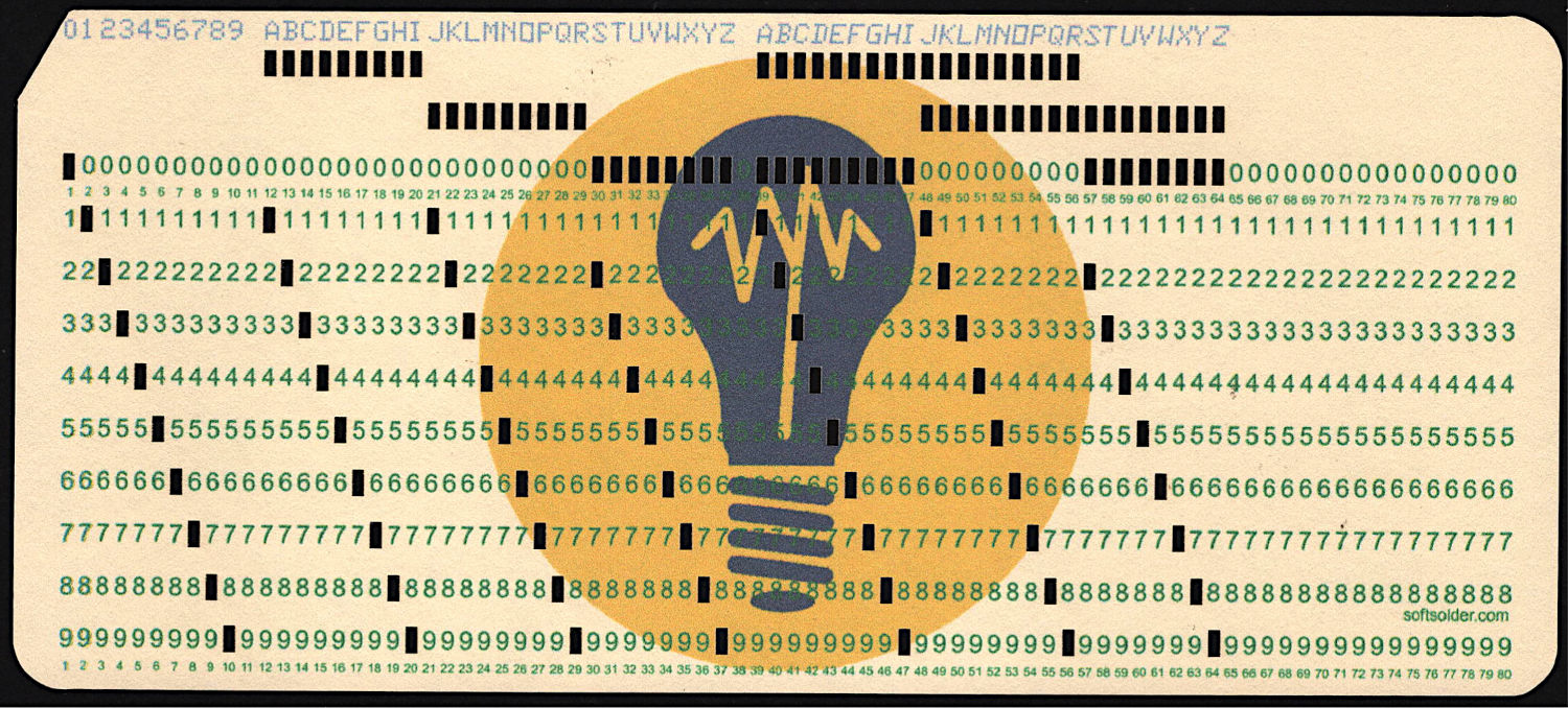
At last, I can make plausible-looking punched cards:
Test Card 3 – punched
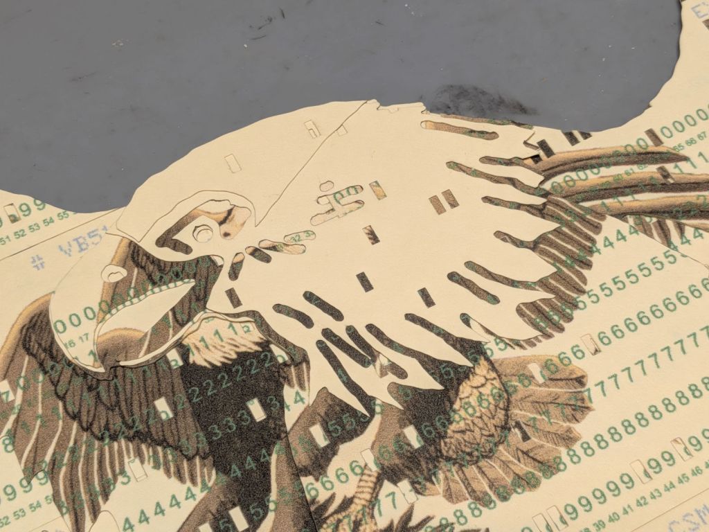
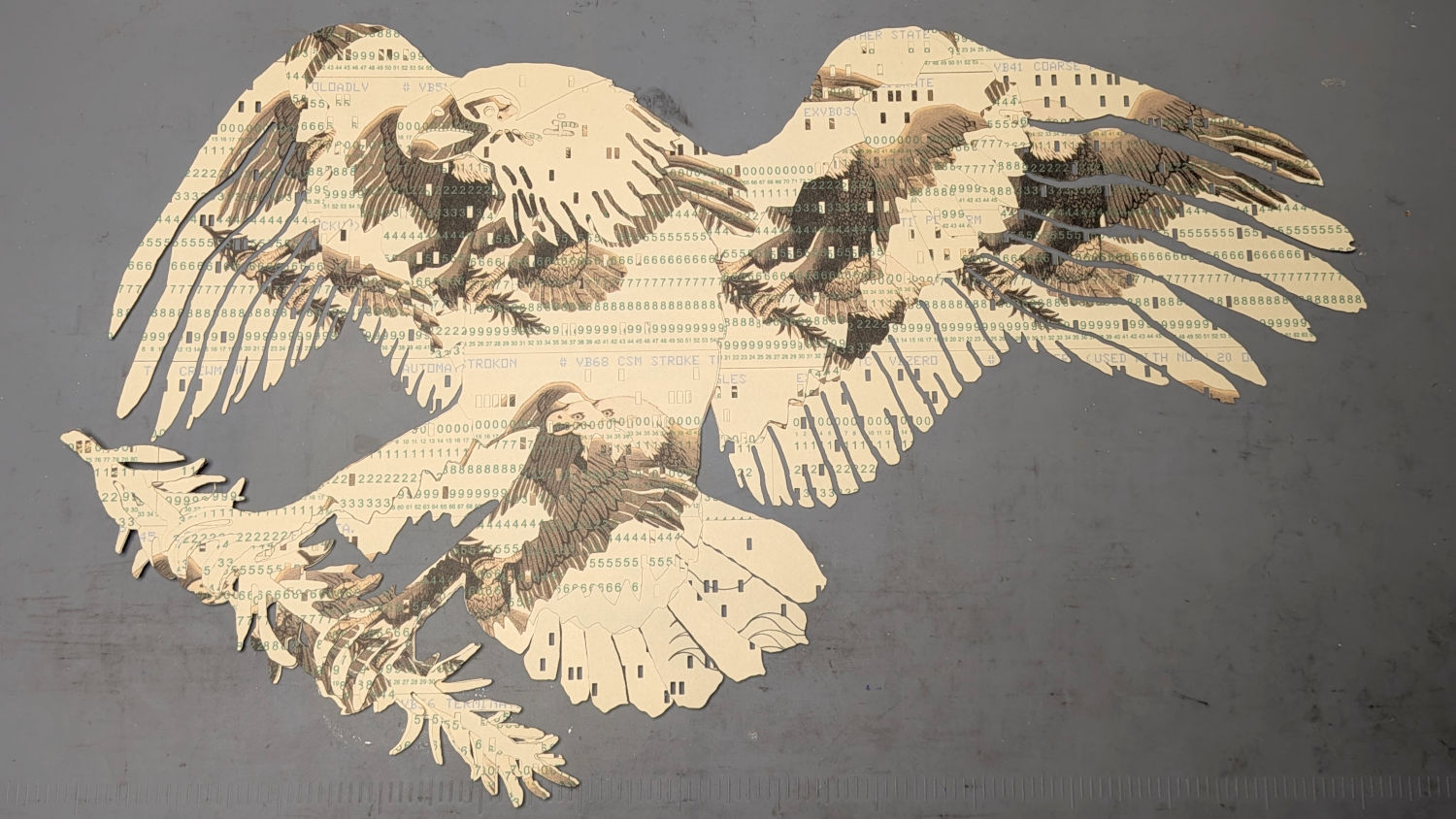
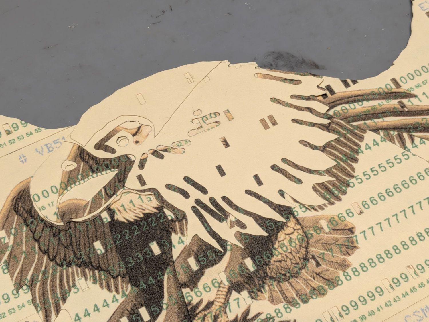
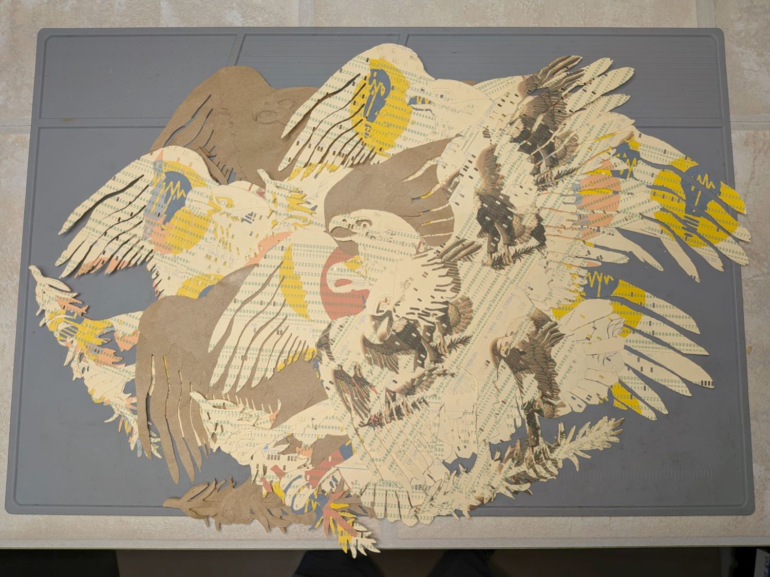
Then chop most of them up to make a layered eagle:
Apollo Eagle – V3 – overview
Back in the beginning, the grand overview explained the card production process, but now I can pull all the blog posts into a more coherent story.
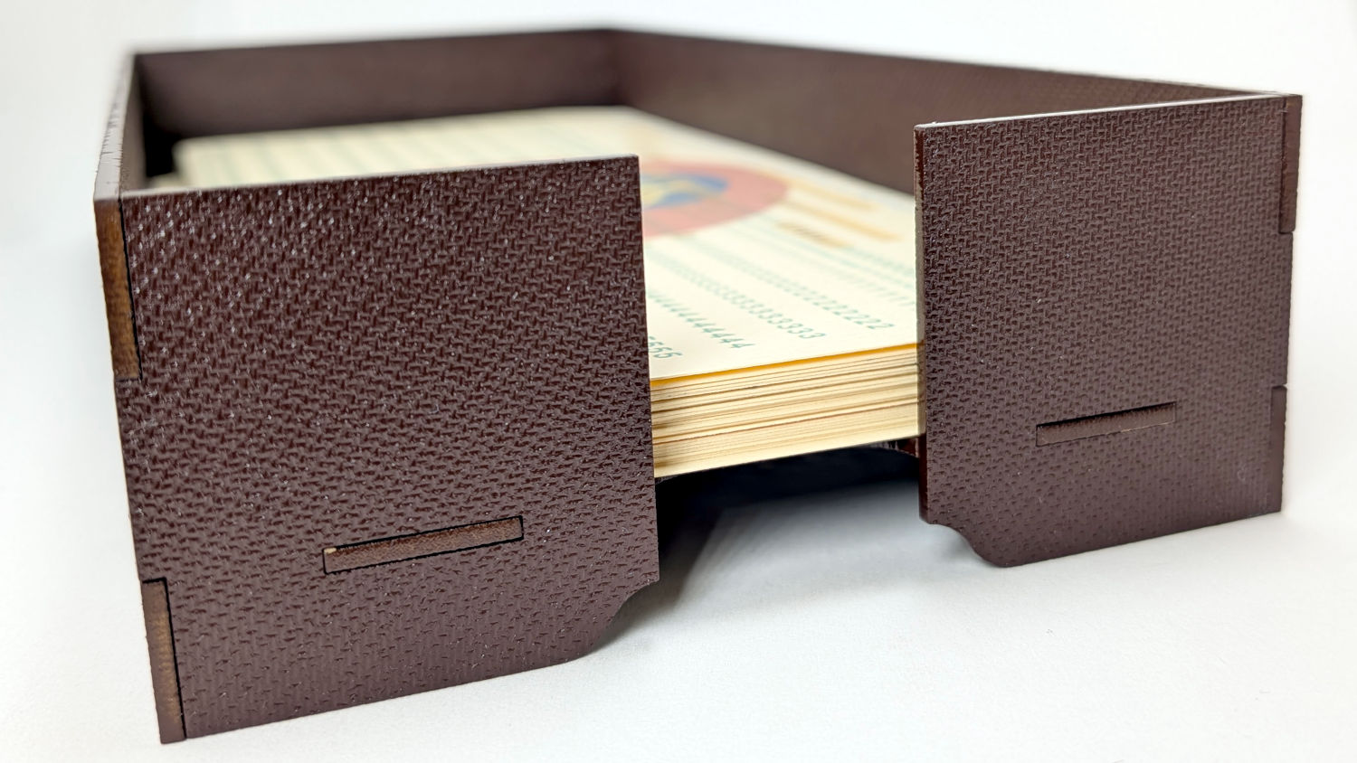
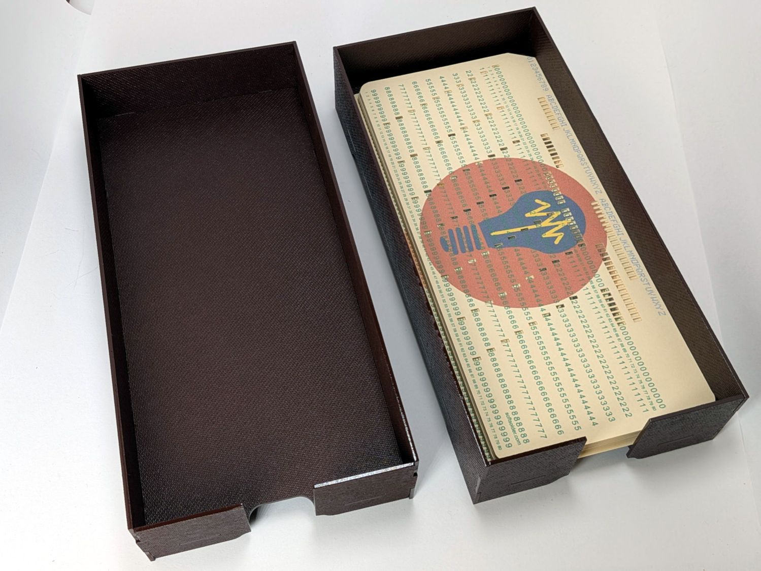
Start by making trays to hold the 1/3 Letter sized printed cards and the final cut cards. A coat of paint improves the result:
Card Storage Tray – front
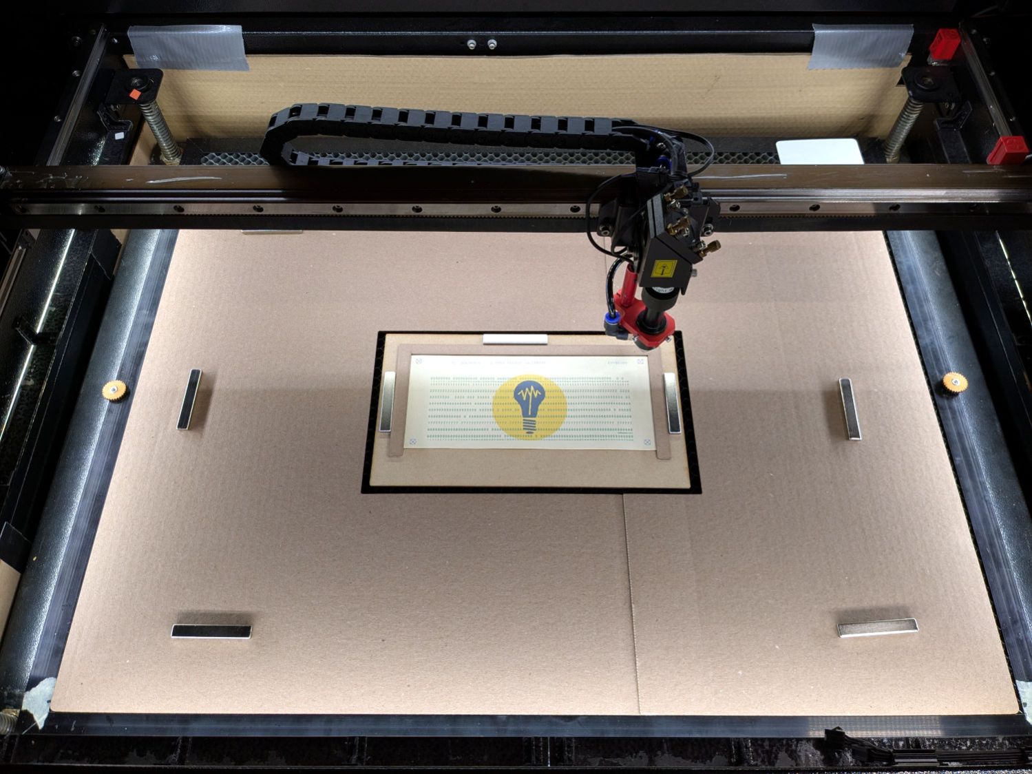
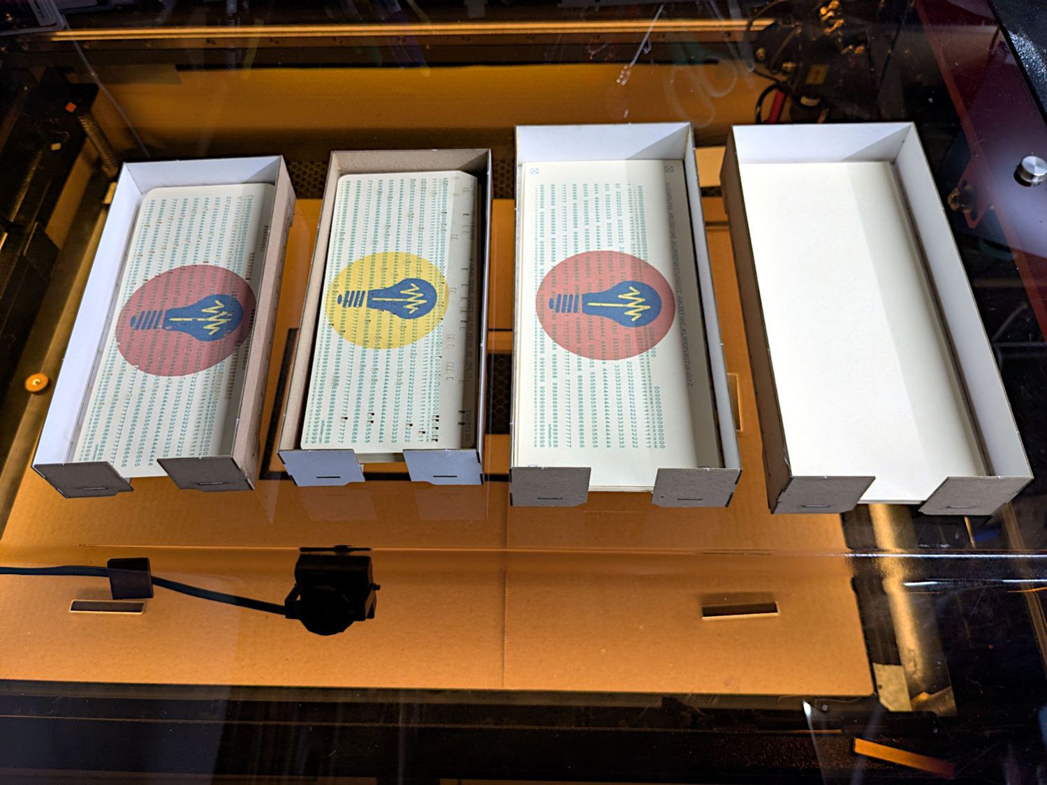
Then make a fixture to position the 1/3 Letter printed cards in the laser and a simple cover for the honeycomb to direct the air flow:
Punched cards – laser fixture overview
The current versions of the Python program to convert a line of text into the SVG images required to print and punch the cards, plus the Bash scripts handling all the command line parameters, are now in a single GitHub Gist . I used the source code from the Apollo 11 CSM AGC for historic reasons.
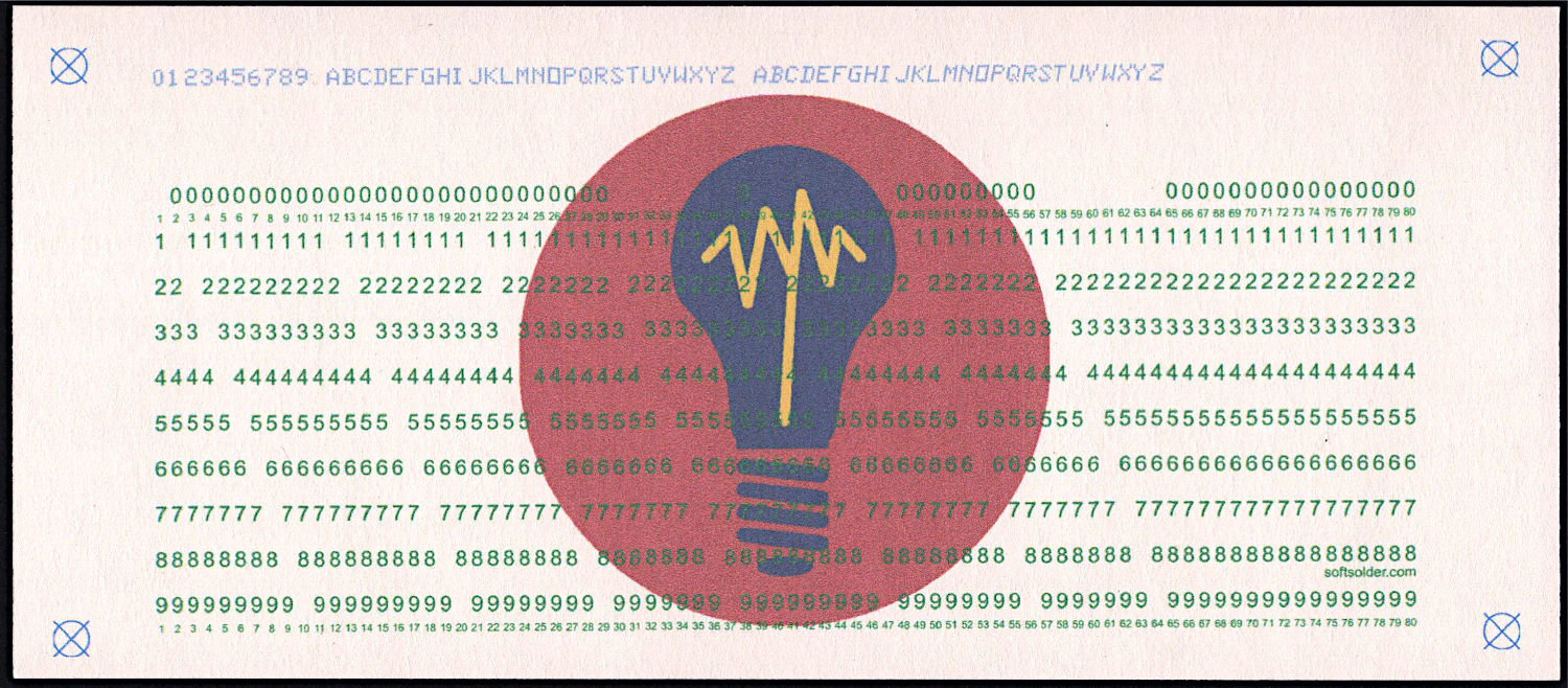
The Bash scripts invoke the Python program twice to produce both the printed layout:
Punched Cards – test card – printed
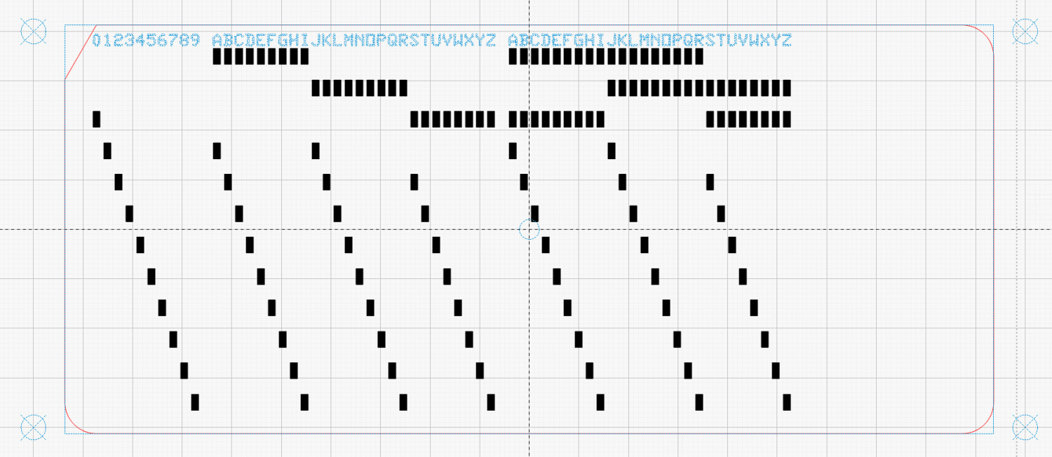
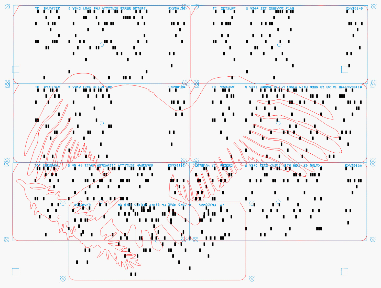
And “punched” holes surrounded by the perimeter cut for the laser:
Because my printer produces slightly off-size printed images, the script uses Inkscape to convert the SVG into a PNG, then downscales the image by a few percent (a different percent on each axis). It composites the card logo onto the PNG and slams the result onto a Letter page in the proper place to hit the 1/3 Letter sheets.
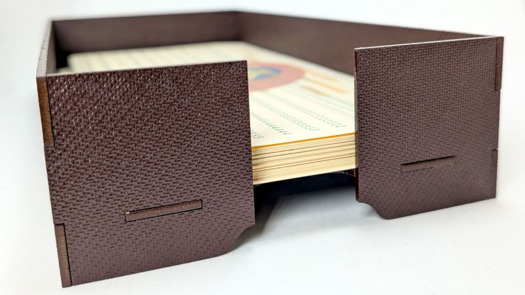
If you must have a stack of punched cards on your desk, a nice tray does wonders for the office decor:
Card Storage Tray – overview
That’s a coat of Rustoleum Painter’s Touch 2x [many more adjectives] Kona Brown Gloss rattlecan paint atop Trocraft Eco board. I sprayed the separate parts on a sheet of newspaper, waited 20 minutes, flipped them over, sprayed the other side, gave them another 20 minutes, and got them inside out of the wind for a day of curing.
They’re held together by cyanoacrylate adhesive dots between the tabs, with accelerator daubed on the other side of the joint to encourage prompt curing. In general I do not like cyanoacrylate, but sometimes it seems like the right hammer for the job.
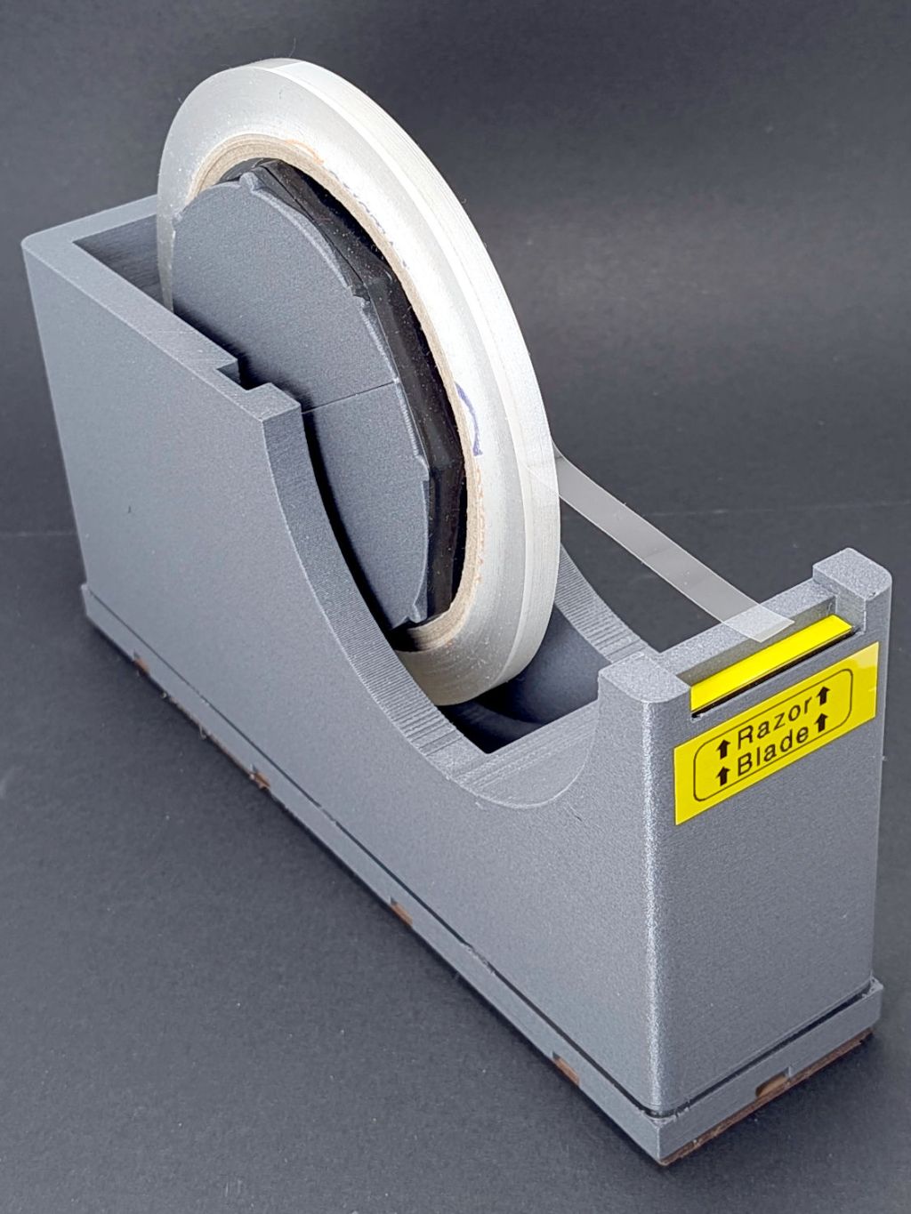
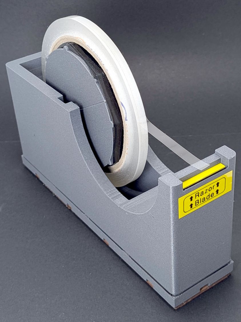
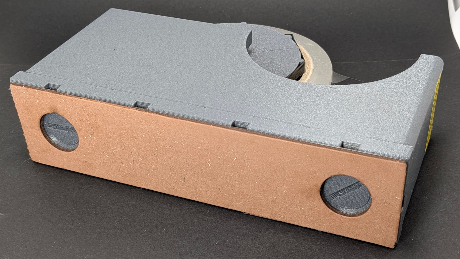
The perspective makes the dispenser look chonkier than it really is.
A wrap of black silicone tape around the spool embiggens it for a snug fit inside the tape core. A casual inspection of other tapes suggest enlarging the spool by a few percent would help, but it’s Good Enough™ as-is.
The two end thumbscrews fasten the 4×1 Gridfinity baseplate to the dispenser; both from Gridfinity Refined:
Gridfinity Tape Dispenser – baseplate
If I had my wits about me, I’d have used a nicely contrasting color for the baseplate, but it is what it is.
Although they’re called “thumbscrews”, the slot is sized for a US quarter (or cart coin).
An OpenSCAD one-liner produces an SVG model of the baseplate:
projection(cut=true) import("Grid 4x1.stl");
Import SVG into LightBurn, delete the magnet pockets, and Fire The Laser on some EVA foam:
Gridfinity Tape Dispenser – foam base
A layer of 3M 300LSE tape holds the foam in place, because neither side sticks well to the goo on a craft adhesive sheet due to their low surface energy. I stuck an oversize rectangle to the foam with the thin adhesive side before cutting, which required a second pass at higher speed.
The thumbscrews also close off the holes in the dispenser bottom through which I poured 275 g = 10 oz of sand for better traction. Steel shot is reputed to be Even Better, although most of the BBs are in the long-arm weight.
The dispenser model includes a printed serrated blade which works as poorly as the author suggested. A length snapped from an ancient Strombecker 4-I (“four eye”) blade in the Box o’ Big X-Acto Blades fits perfectly, works wonderfully well, and is sufficiently inconspicuous to warrant the warning label. An X-Acto #26 Whittling Blade would probably snap down equally well.
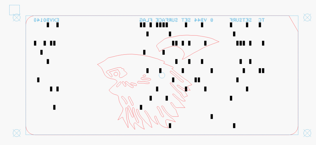
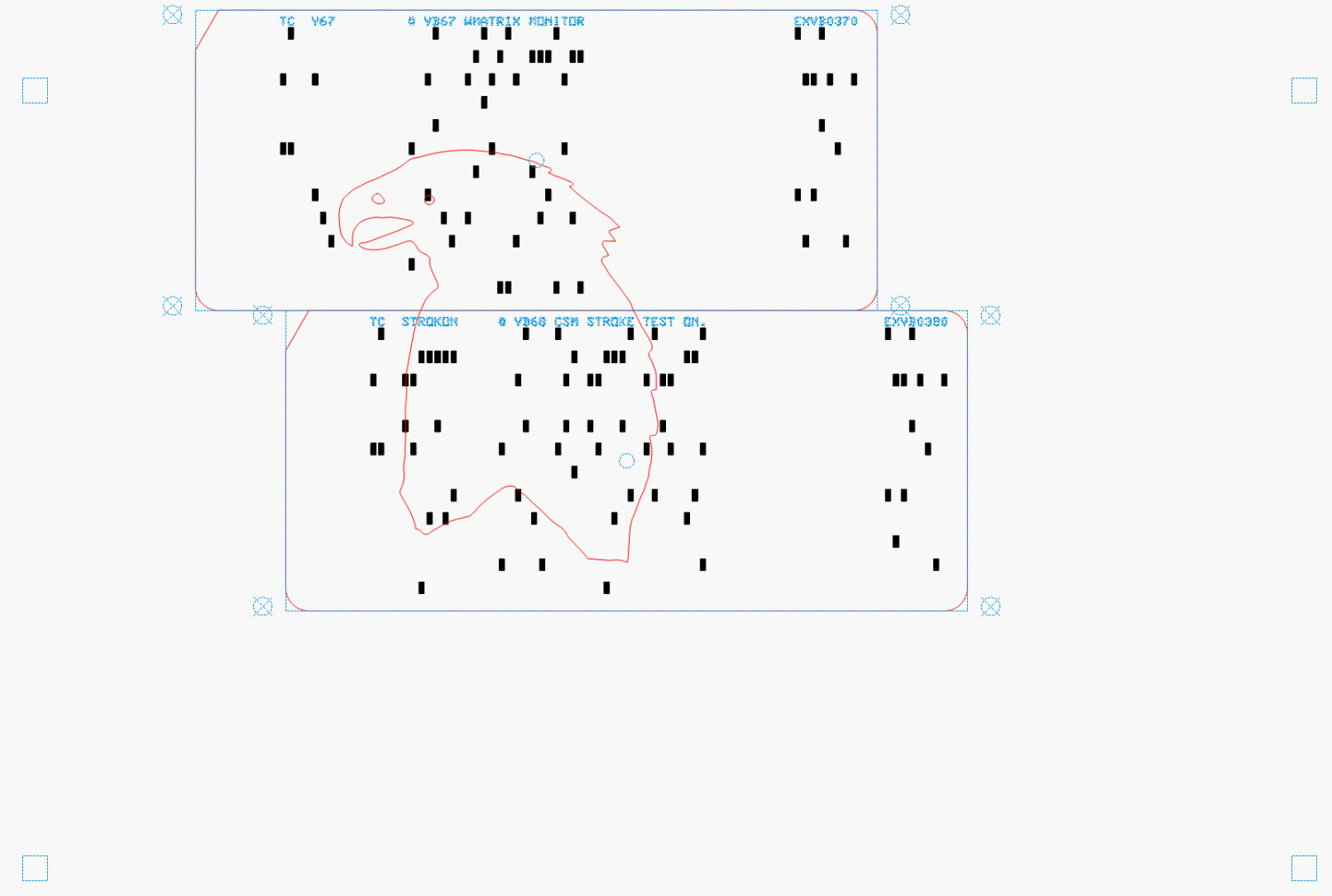
The small squares near the corners of the image appear on every layer to properly register all the eagle outlines.
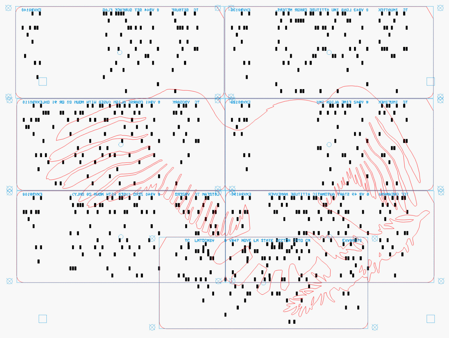
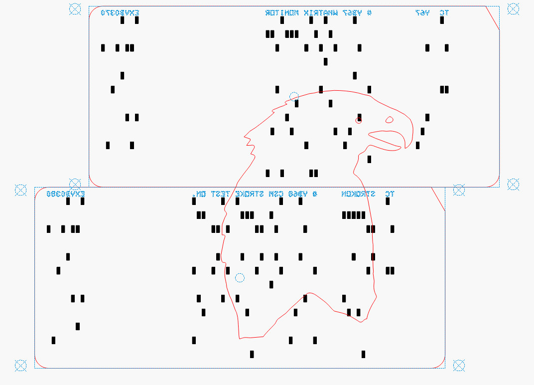
Mirroring the layout produces the hole pattern as seen from the back side of the cards, where the tape is applied:
Apollo Eagle – V4 Layer 7 card layout – mirrored
Then it’s (relatively) easy to align the cards while muttering “the rightmost hole in the lower sequence number is just about aligned with the upper card edge, which puts the middle-ish hole in the group of four in the 9 row over the left hole of those two” and so on and so forth. Cut off a strip of tape, carefully lay it along the joint between the cards, and add them to the outgoing pile.
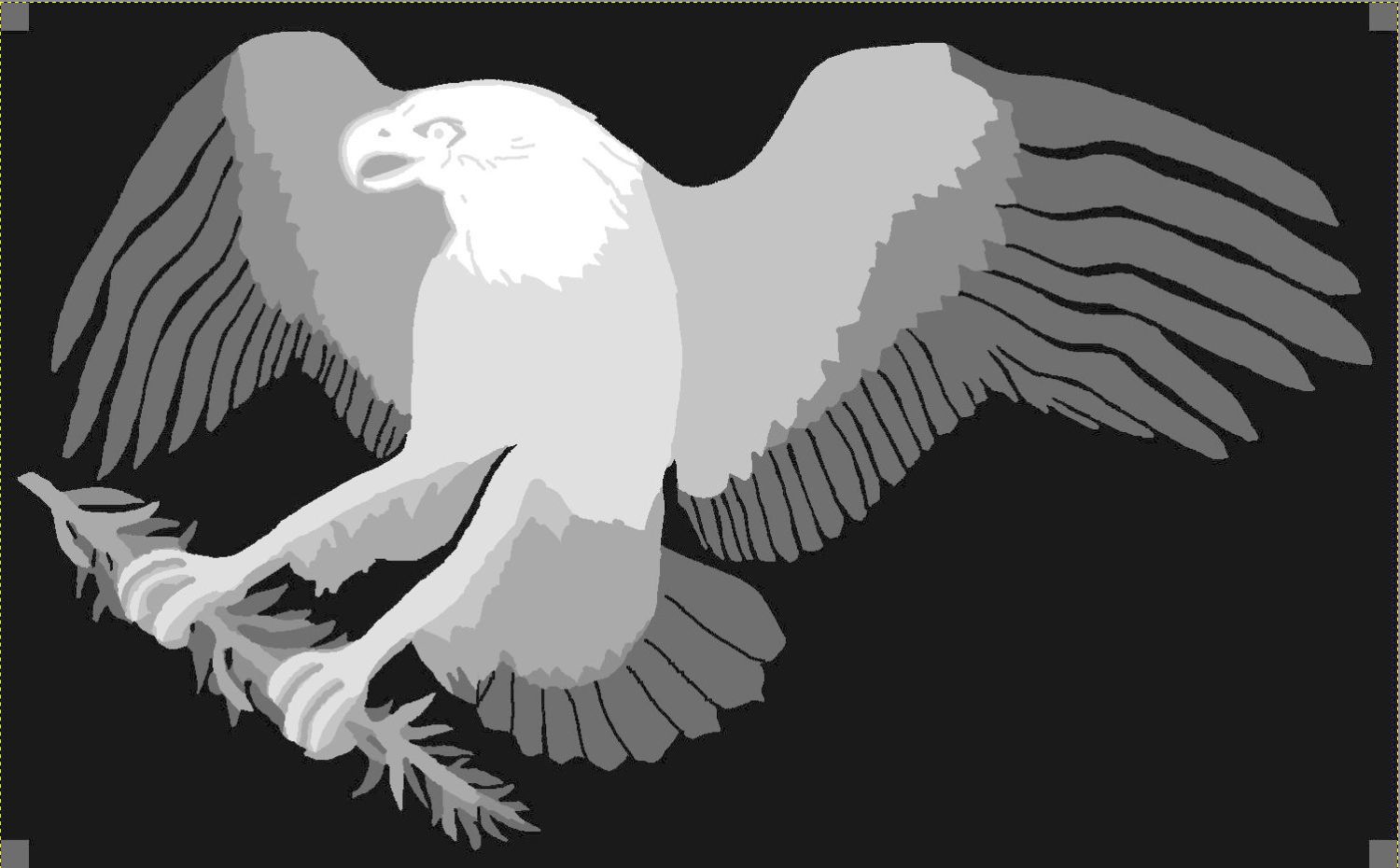
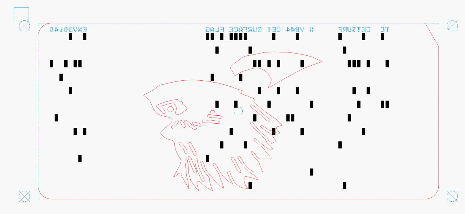
The top two layers are cut with the back = unprinted = blank side of the card upward to produce the eagle’s white head, with the outlines strategically located to avoid shredding the feathers with holes:
Apollo Eagle – V4 Layer 8-9 card layout
The value of this process becomes more apparent for the nine cards making up the bottom layer:
Apollo Eagle – V4 Layer 1 cards
Most of the white tail comes from the reversed card in the bottom row, inset into the two cards above it. The next layer covers those sections of the legs and olive branch, which is easy to confirm by aligning the layers using their border squares.
The layout mirrored for easier taping:
Apollo Eagle – V4 Layer 1 cards – mirrored
This is from a previous layout, but the improvement is obvious:
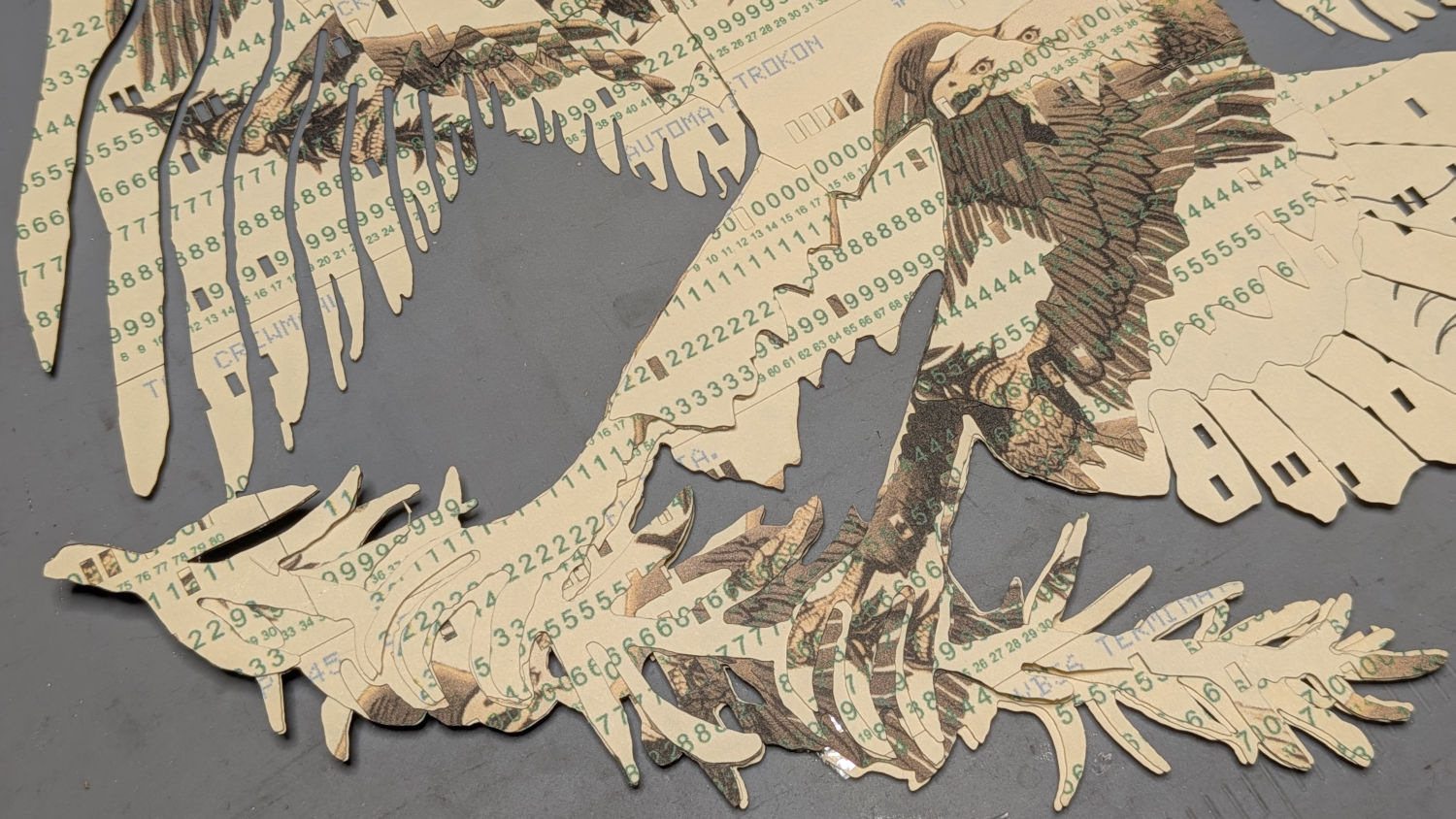
Apollo Eagle – V3 – tail
The trick with all this is to select only the eagle outline for cutting amid all the card details. Although putting the cards on a tool layer would avoid that problem, the holes are much less visible and they’re pretty much the entire point of this process.
Aligning the taped cards on the platform with the to-be-cut outline follows much the same process as aligning the printed cards for punching:
Select the cards and the eagle outline
Snap to the middle of the LightBurn workspace with the P key
Focus the laser on the cards if you haven’t already done so
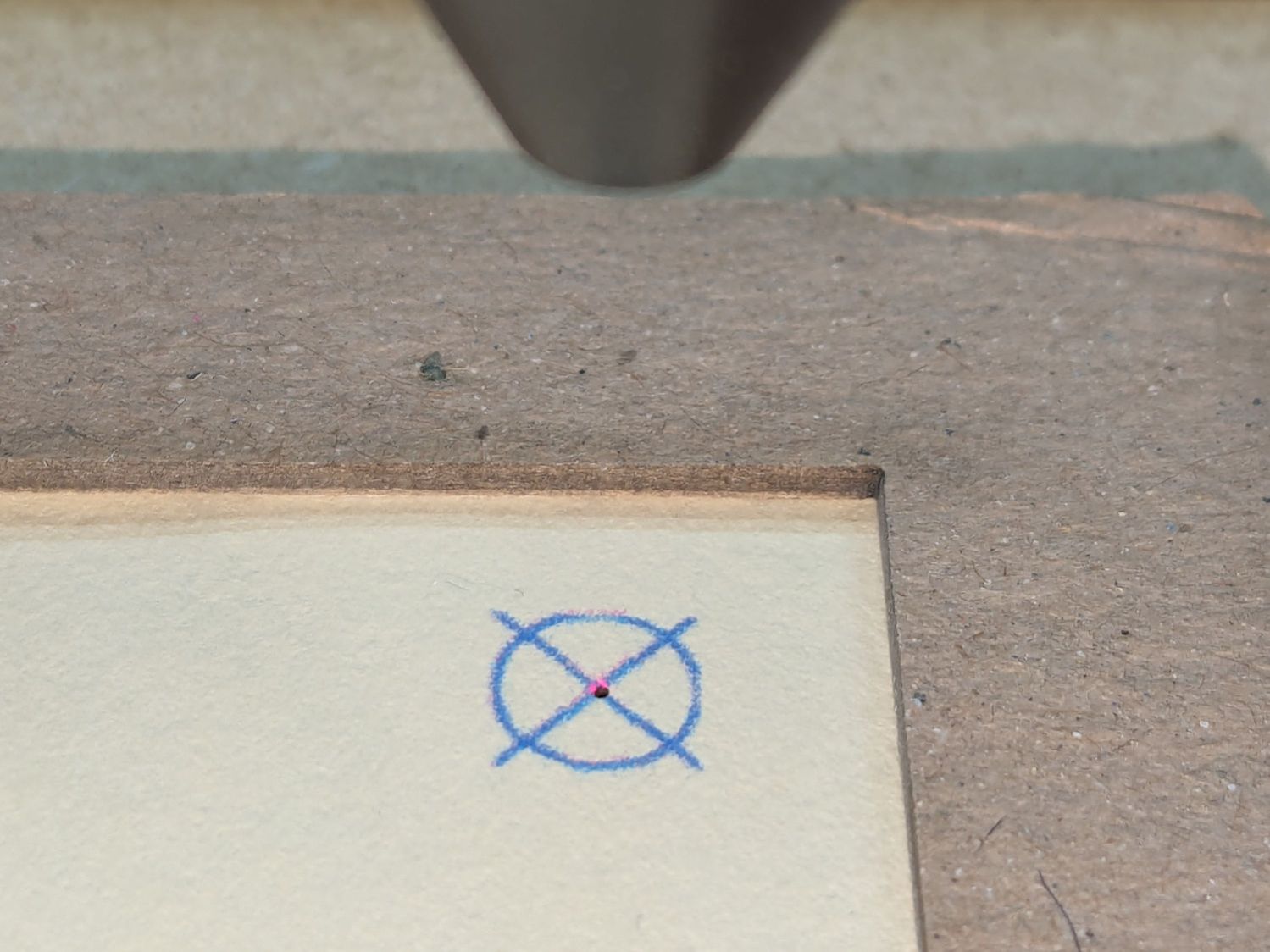
Move the laser head to one of the card bevels using Ctrl-L and clicking on one end of the bevel
Skootch the cards to put that bevel at the red dot pointer location under the laser head
Move the laser head to another bevel
Skootch the cards as needed
Iterate until satisfied
Fire The Laser
Although each card layout has the four targets used to cut it from the printed card stock, those targets no longer exist on the cards because they’ve been cut off.
You could use Print and Cut to align the LightBurn workspace to the cards, but it’s easier and faster to just skootch the cards around.
Actually cutting the outline takes a few seconds and is kinda anticlimactic after all that setup.
Stipulated: nobody ever ran punched cards through a multi-color printing process. A posterized version of the Apollo 11 mission patch eagle just seemed appropriate for cards containing a chunk of the mission source code.
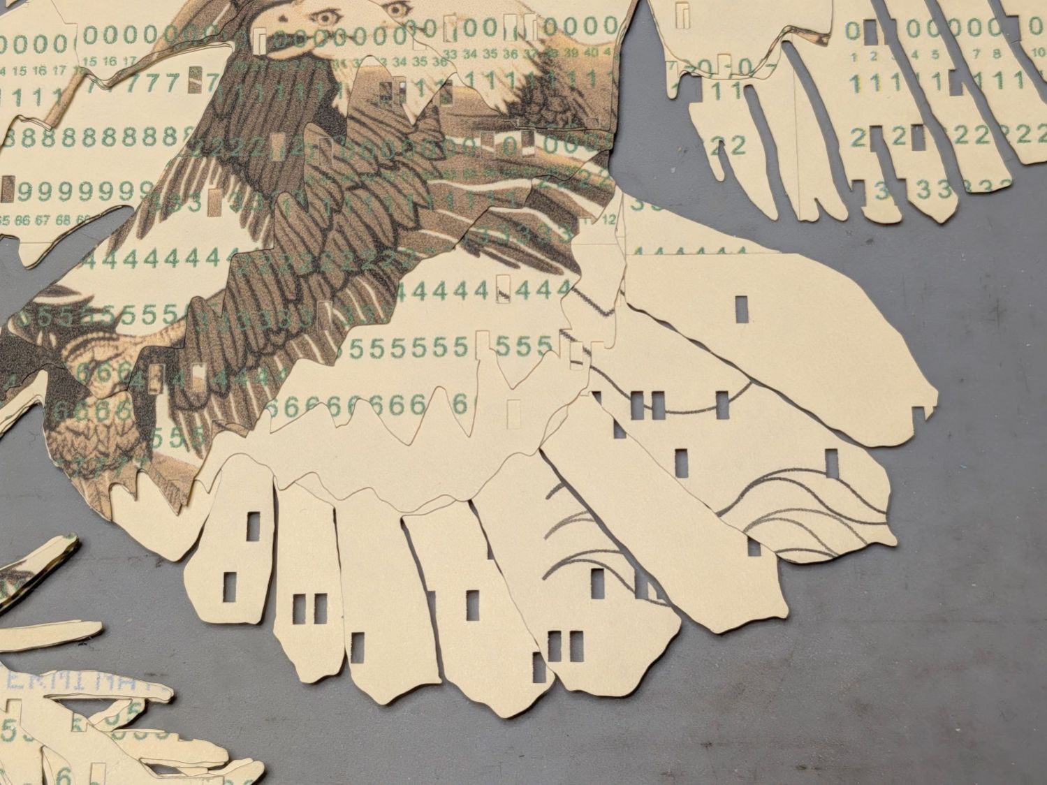
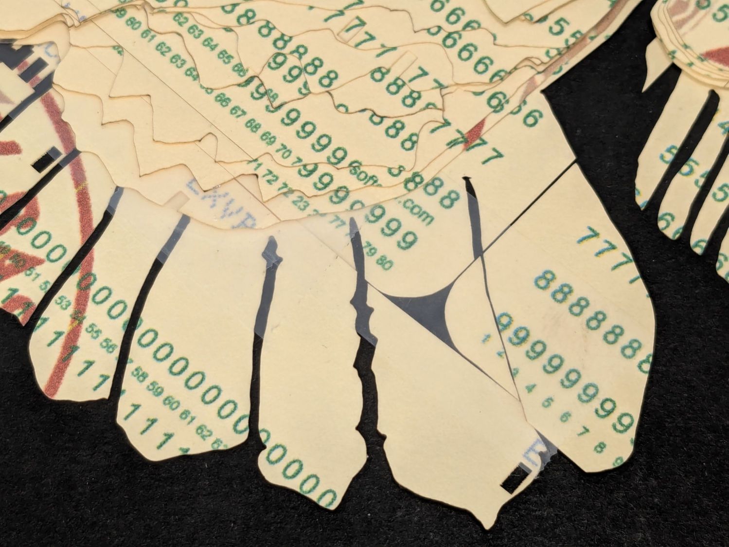
Putting the tail feathers on two layers of reversed cards definitely improved the outcome:
Apollo Eagle – V3 – tail
The lines across two of the tail feathers come from inadvertently printing a quilting pattern intended for Letter paper after setting up a stack of 1/3 Letter blanks. Trust me on this: you do not discard any salvageable blooper cards.
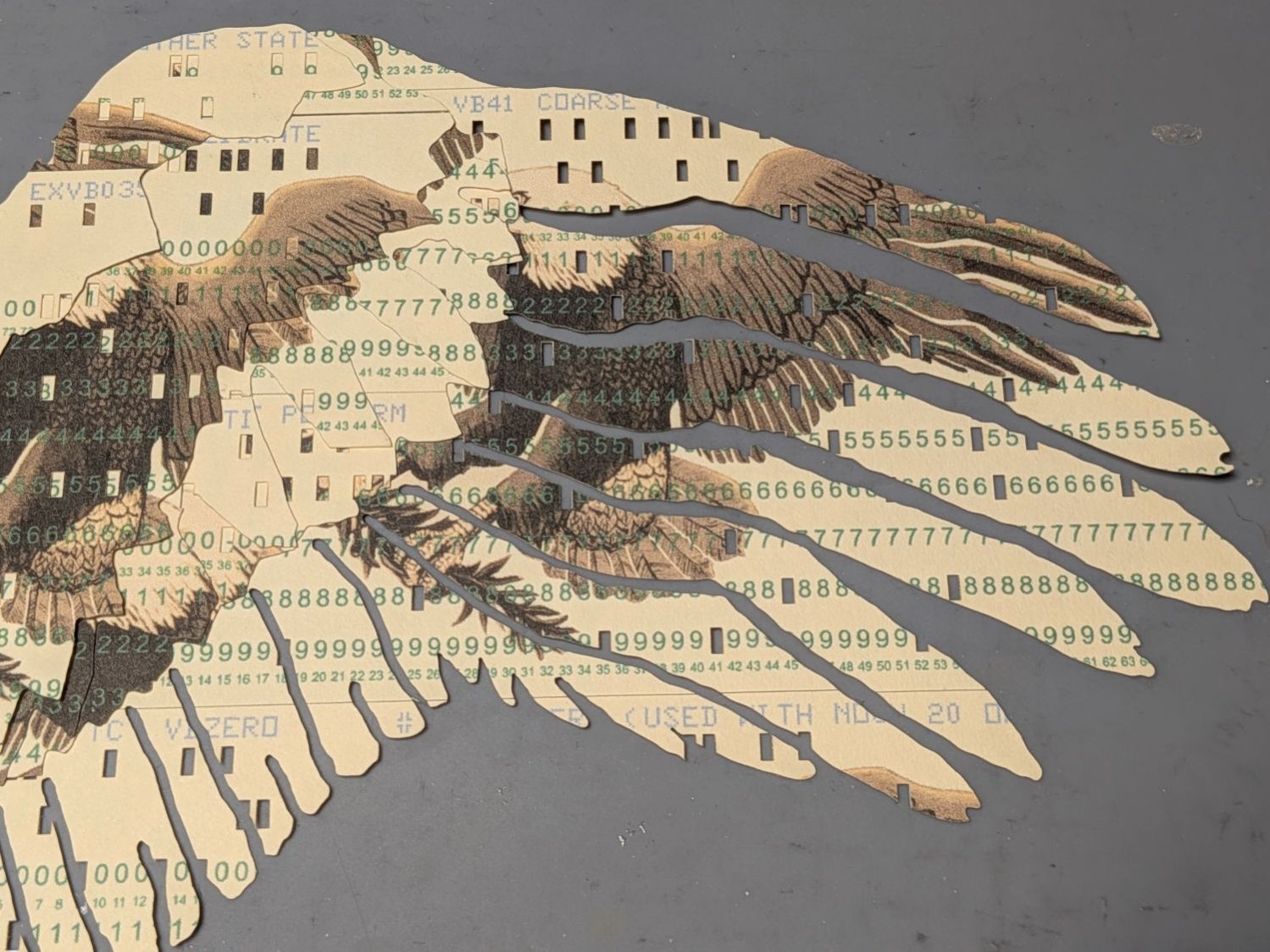
The wing feathers get more definition and have sculptured upper layers:
Apollo Eagle – V3 – wing
The olive branch improved with fewer layers and contouring the claws makes them less chunky:
Apollo Eagle – V3 – olive branch
The beak and head now have slight contouring, with the neck feathers standing out nicely over the logo below:
Apollo Eagle – V3 – head
Although this is the third almost-ready version, it rests on the wings of many previous attempts:
Apollo Eagle – layered trials
The card joints on successive layers are now farther apart, although the long run across the middle of the body stands out more than I expected. The small pieces of cards at the top of the wings need more contrast.
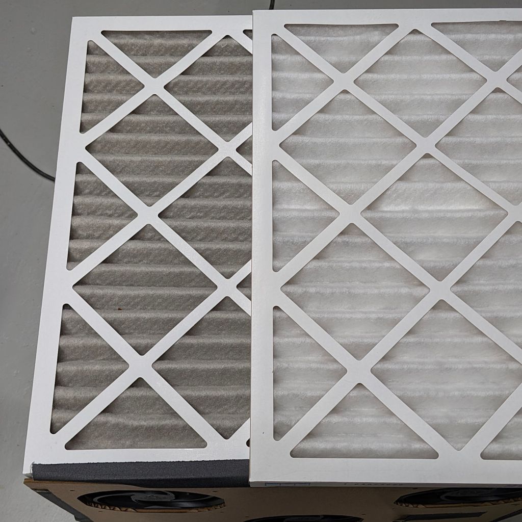
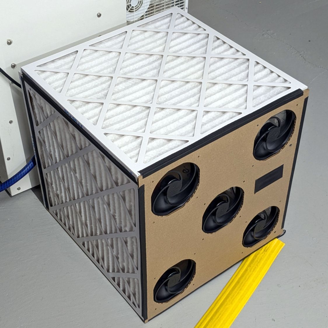
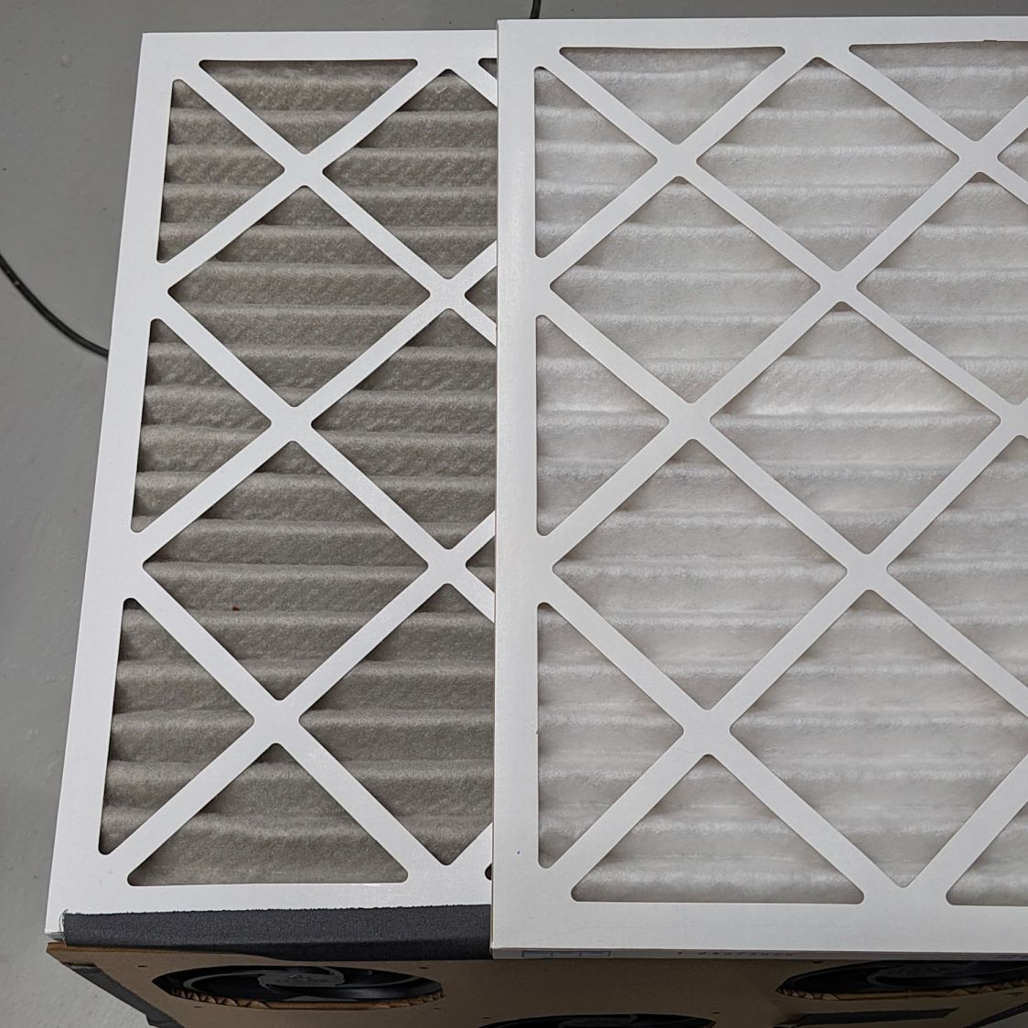
Running continuously for three months made the air filters look like this (with an unused filter on top for comparison):
Basement Air Filter Box – 3 months – A
I have not stretched the image contrast, so the new filter isn’t the pure white in the top picture, but it’s still about the same white as the cardboard frame. The floor is, indeed, painted gray.
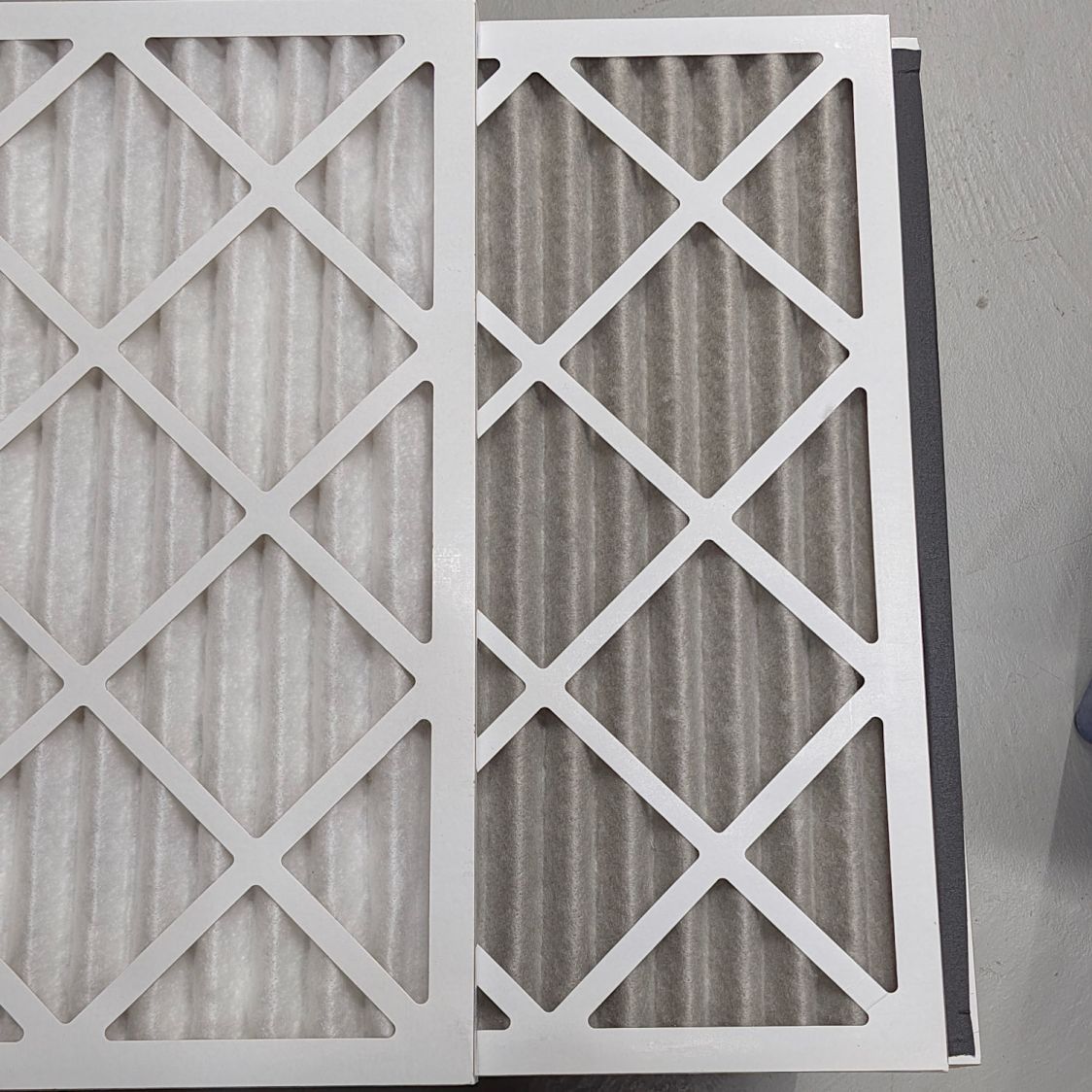
Looking at the pleats in the other direction to show I’m not making it up:
Basement Air Filter Box – 3 months – B
The inside surface of the filters has the same gray appearance. The fans are, unsurprisingly, immaculate.
Totally did not expect that!
The filters sport a MERV 13 rating and snag “most smoke” from the passing air, so they’ve been collecting any fumes not sucked out of the laser cutter, along with whatever arises from other Basement Shop™ activities.
So I’ll buy another set of filters, build another box, and see what accumulates during the next three months.