|
// Astable Multivibrator |
|
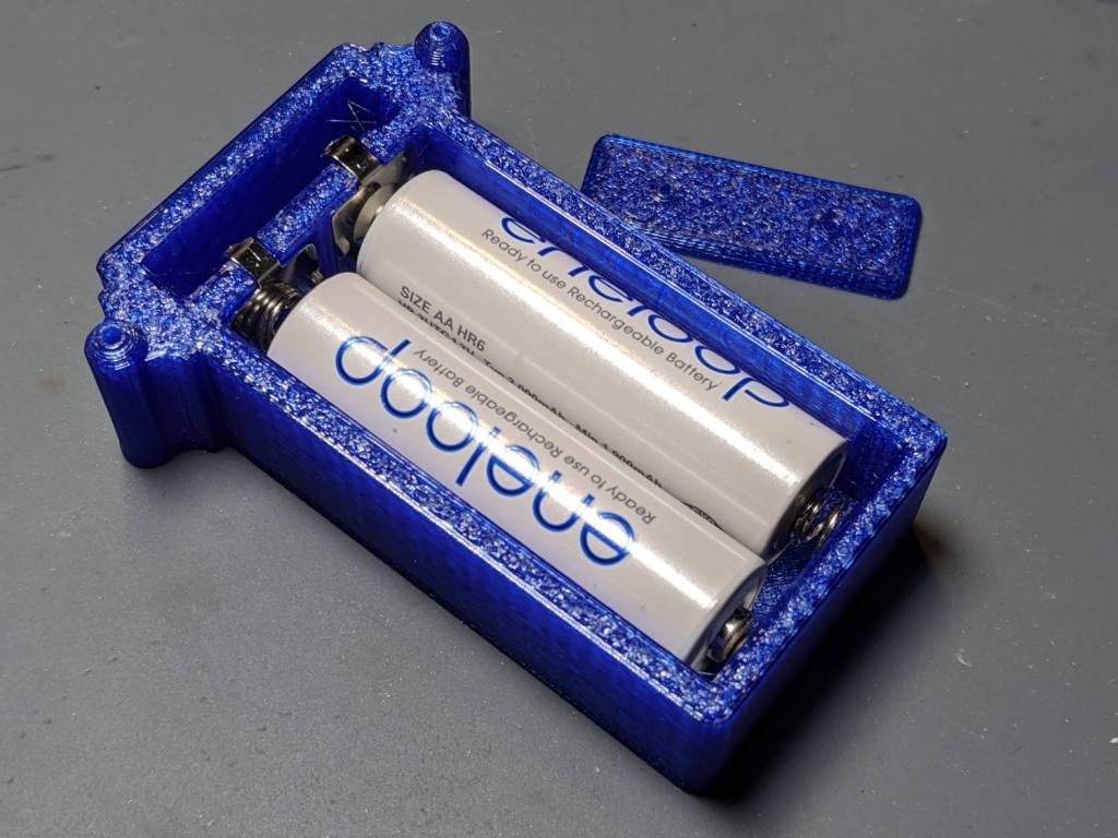
// Holder for Alkaline cells |
|
// Ed Nisley KE4ZNU August 2020 |
|
|
|
/* [Layout options] */ |
|
|
|
CellName = "AA"; // [AA] — does not work with anything else |
|
NumCells = 2; |
|
|
|
Layout = "Case"; // [Build,Show,Lid] |
|
|
|
Struts = -1; // [0:None, -1:Dual, 1:Quad] |
|
|
|
// Extrusion parameters – must match reality! */ |
|
|
|
/* [Hidden] */ |
|
|
|
ThreadThick = 0.25; |
|
ThreadWidth = 0.40; |
|
|
|
HoleWindage = 0.2; |
|
|
|
function IntegerMultiple(Size,Unit) = Unit * ceil(Size / Unit); |
|
function IntegerLessMultiple(Size,Unit) = Unit * floor(Size / Unit); |
|
|
|
Protrusion = 0.1; // make holes end cleanly |
|
|
|
inch = 25.4; |
|
|
|
//- Basic dimensions |
|
|
|
WallThick = IntegerMultiple(3.0,ThreadWidth); |
|
CornerRadius = WallThick/2; |
|
|
|
FloorThick = IntegerMultiple(3.0,ThreadThick); |
|
|
|
TopThick = IntegerMultiple(2.0,ThreadThick); |
|
|
|
WireOD = 1.7; // wiring from pins to circuitry |
|
|
|
Gap = 5.0; |
|
|
|
// Cylindrical cell sizes |
|
// https://en.wikipedia.org/wiki/List_of_battery_sizes#Cylindrical_batteries |
|
|
|
CELL_NAME = 0; |
|
CELL_OD = 1; |
|
CELL_OAL = 2; |
|
|
|
CellData = [ |
|
["AAAA",8.3,42.5], |
|
["AAA",10.5,44.5], |
|
["AA",14.5,50.5], |
|
["C",26.2,50], |
|
["D",34.2,61.5], |
|
["A23",10.3,28.5], |
|
["CR123A",17.0,34.5], |
|
["18650",18.8,65.2], // bare 18650 with button end |
|
["18650Prot",19.0,70.0], // protected 18650 = 19670 plus a bit |
|
]; |
|
|
|
CellIndex = search([CellName],CellData,1,0)[0]; |
|
echo(str("Cell index: ",CellIndex," = ",CellData[CellIndex][CELL_NAME])); |
|
|
|
//- Contact dimensions |
|
|
|
CONTACT_NAME = 0; |
|
CONTACT_WIDE = 1; |
|
CONTACT_HIGH = 2; |
|
CONTACT_THICK = 3; // plate thickness |
|
CONTACT_TIP = 4; // tip to rear face |
|
CONTACT_TAB = 5; // solder tab width |
|
|
|
ContactData = [ |
|
["AA+",12.2,12.2,0.3,1.7,3.5], // pos bump |
|
["AA-",12.2,12.2,0.3,5.0,3.5], // half-compressed neg spring |
|
["AA+-",28.2,12.2,0.3,5.0,0], // pos-neg bridge |
|
|
|
["Li+",18.5,16.0,0.3,2.8,5.5], |
|
["Li-",18.5,16.0,0.3,6.0,5.5], |
|
]; |
|
|
|
function ConDat(name,dim) = ContactData[search([name],ContactData,1,0)[0]][dim]; |
|
|
|
ContactRecess = 2*ConDat(str(CellName,"+"),CONTACT_THICK); |
|
ContactOC = CellData[CellIndex][CELL_OD]; |
|
|
|
WireBay = 6.0; // room for wiring to contacts |
|
|
|
//- Wire struts |
|
|
|
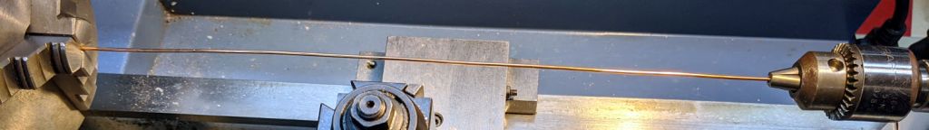
StrutDia = 1.6; // AWG 14 = 1.6 mm |
|
StrutSides = 3*4; |
|
|
|
ID = 0; |
|
OD = 1; |
|
LENGTH = 2; |
|
|
|
StrutBase = [StrutDia,StrutDia + 2*5*ThreadWidth, // ID = wire, OD = buildable |
|
FloorThick + CellData[CellIndex][CELL_OD]]; // base is flush with cell top |
|
|
|
//- Holder dimensions |
|
|
|
BatterySize = [CellData[CellIndex][CELL_OAL] + // cell |
|
ConDat(str(CellName,"+"),CONTACT_TIP) + // pos contact |
|
ConDat(str(CellName,"-"),CONTACT_TIP) – // neg contact |
|
2*ContactRecess, // sink into wall |
|
NumCells*CellData[CellIndex][CELL_OD], |
|
CellData[CellIndex][CELL_OD] |
|
]; |
|
|
|
echo(str("Battery space: ",BatterySize)); |
|
|
|
CaseSize = [3*WallThick + // end walls + wiring partition |
|
BatterySize.x + // cell |
|
WireBay, // wiring bay |
|
2*WallThick + BatterySize.y, |
|
FloorThick + BatterySize.z |
|
]; |
|
|
|
BatteryOffset = (CaseSize.x – (2*WallThick + |
|
CellData[CellIndex][CELL_OAL] + |
|
ConDat(str(CellName,"-"),CONTACT_TIP)) |
|
) /2 ; |
|
|
|
ThumbRadius = 0.75 * CaseSize.z; |
|
|
|
|
|
StrutOC = [IntegerLessMultiple(CaseSize.x – 2*CornerRadius -2*StrutBase[OD],5.0), |
|
IntegerMultiple(CaseSize.y + StrutBase[OD],5.0)]; |
|
|
|
StrutAngle = atan(StrutOC.y/StrutOC.x); |
|
|
|
echo(str("Strut OC: ",StrutOC)); |
|
|
|
LidSize = [2*WallThick + WireBay + ConDat(str(CellName,"+"),CONTACT_THICK), CaseSize.y, FloorThick/2]; |
|
|
|
|
|
//———————- |
|
// Useful routines |
|
|
|
module PolyCyl(Dia,Height,ForceSides=0) { // based on nophead's polyholes |
|
|
|
Sides = (ForceSides != 0) ? ForceSides : (ceil(Dia) + 2); |
|
|
|
FixDia = Dia / cos(180/Sides); |
|
|
|
cylinder(r=(FixDia + HoleWindage)/2,h=Height,$fn=Sides); |
|
} |
|
|
|
|
|
|
|
//– Overall case with origin at battery center |
|
|
|
module Case() { |
|
|
|
difference() { |
|
union() { |
|
hull() |
|
for (i=[-1,1], j=[-1,1]) |
|
translate([i*(CaseSize.x/2 – CornerRadius), |
|
j*(CaseSize.y/2 – CornerRadius), |
|
0]) |
|
cylinder(r=CornerRadius/cos(180/8),h=CaseSize.z,$fn=8); // cos() fixes undersize spheres! |
|
|
|
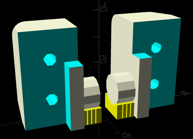
if (Struts) |
|
for (i = (Struts == 1) ? [-1,1] : -1) { // strut bases |
|
hull() |
|
for (j=[-1,1]) |
|
translate([i*StrutOC.x/2,j*StrutOC.y/2,0]) |
|
rotate(180/StrutSides) |
|
cylinder(d=StrutBase[OD],h=StrutBase[LENGTH],$fn=StrutSides); |
|
|
|
translate([i*StrutOC.x/2,0,StrutBase[LENGTH]/2]) |
|
cube([2*StrutBase[OD],StrutOC.y,StrutBase[LENGTH]],center=true); // blocks for fairing |
|
|
|
for (j=[-1,1]) // hemisphere caps |
|
translate([i*StrutOC.x/2, |
|
j*StrutOC.y/2, |
|
StrutBase[LENGTH]]) |
|
rotate(180/StrutSides) |
|
sphere(d=StrutBase[OD]/cos(180/StrutSides),$fn=StrutSides); |
|
|
|
} |
|
} |
|
|
|
translate([BatteryOffset,0,BatterySize.z/2 + FloorThick]) // cells |
|
cube(BatterySize + [0,0,Protrusion],center=true); |
|
|
|
translate([BatterySize.x/2 + BatteryOffset + ContactRecess/2 – Protrusion/2, // contacts |
|
0, |
|
BatterySize.z/2 + FloorThick]) |
|
cube([ContactRecess + Protrusion, |
|
ConDat(str(CellName,"+-"),CONTACT_WIDE), |
|
ConDat(str(CellName,"+-"),CONTACT_HIGH) |
|
],center=true); |
|
|
|
translate([-(BatterySize.x/2 – BatteryOffset + ContactRecess/2 – Protrusion/2), |
|
ContactOC/2, |
|
BatterySize.z/2 + FloorThick]) |
|
cube([ContactRecess + Protrusion, |
|
ConDat(str(CellName,"+"),CONTACT_WIDE), |
|
ConDat(str(CellName,"+"),CONTACT_HIGH) |
|
],center=true); |
|
|
|
translate([-(BatterySize.x/2 – BatteryOffset + ContactRecess/2 – Protrusion/2), |
|
-ContactOC/2, |
|
BatterySize.z/2 + FloorThick]) |
|
cube([ContactRecess + Protrusion, |
|
ConDat(str(CellName,"-"),CONTACT_WIDE), |
|
ConDat(str(CellName,"-"),CONTACT_HIGH) |
|
],center=true); |
|
|
|
translate([-CaseSize.x/2 + WireBay/2 + WallThick, // wire bay |
|
0, |
|
BatterySize.z/2 + FloorThick + Protrusion/2]) |
|
cube([WireBay, |
|
BatterySize.y, |
|
BatterySize.z + Protrusion |
|
],center=true); |
|
|
|
for (j=[-1,1]) |
|
translate([-(BatterySize.x/2 – BatteryOffset + WallThick/2), // contact tabs |
|
j*ContactOC/2, |
|
BatterySize.z + FloorThick – Protrusion]) |
|
cube([2*WallThick, |
|
ConDat(str(CellName,"+"),CONTACT_TAB), |
|
(BatterySize.z – ConDat(str(CellName,"+"),CONTACT_HIGH)) |
|
],center=true); |
|
|
|
if (false) |
|
translate([0,0,CaseSize.z]) // finger cutout |
|
rotate([90,00,0]) |
|
cylinder(r=ThumbRadius,h=2*CaseSize.y,center=true,$fn=22); |
|
|
|
if (Struts) |
|
for (i2 = (Struts == 1) ? [-1,1] : -1) { // strut wire holes and fairing |
|
for (j=[-1,1]) |
|
translate([i2*StrutOC.x/2,j*StrutOC.y/2,FloorThick]) |
|
rotate(180/StrutSides) |
|
PolyCyl(StrutBase[ID],2*StrutBase[LENGTH],StrutSides); |
|
|
|
for (i=[-1,1], j=[-1,1]) // fairing cutaways |
|
translate([i*StrutBase[OD] + (i2*StrutOC.x/2), |
|
j*StrutOC.y/2, |
|
-Protrusion]) |
|
rotate(180/StrutSides) |
|
PolyCyl(StrutBase[OD],StrutBase[LENGTH] + 2*Protrusion,StrutSides); |
|
} |
|
|
|
} |
|
} |
|
|
|
|
|
module Lid() { |
|
|
|
difference() { |
|
hull() |
|
for (i=[-1,1], j=[-1,1], k=[-1,1]) |
|
translate([i*(LidSize.x/2 – CornerRadius), |
|
j*(LidSize.y/2 – CornerRadius), |
|
k*(LidSize.z – CornerRadius)]) // double thickness for flat bottom |
|
sphere(r=CornerRadius/cos(180/8),$fn=8); |
|
|
|
translate([0,0,-LidSize.z]) // remove bottom |
|
cube([(LidSize.x + 2*Protrusion),(LidSize.y + 2*Protrusion),2*LidSize.z],center=true); |
|
|
|
for (j=[-1,1]) // wire holes |
|
translate([0,j*LidSize.y/4,-Protrusion]) |
|
PolyCyl(WireOD,2*LidSize.z,6); |
|
|
|
} |
|
} |
|
|
|
|
|
//——————- |
|
// Build it! |
|
|
|
if (Layout == "Case") |
|
Case(); |
|
|
|
if (Layout == "Lid") |
|
Lid(); |
|
|
|
if (Layout == "Build") { |
|
rotate(-90) |
|
translate([CaseSize.x/2 + Gap,0,0]) |
|
Case(); |
|
rotate(-90) |
|
translate([-LidSize.x/2 – Gap,0,0]) |
|
Lid(); |
|
} |
|
|
|
if (Layout == "Show") { |
|
Case(); |
|
translate([-CaseSize.x/2 + LidSize.x/2,0,(CaseSize.z + Gap)]) |
|
Lid(); |
|
} |
|
|
|
|
|
|