The Smell of Molten Projects in the Morning

Ed Nisley's Blog: Shop notes, electronics, firmware, machinery, 3D printing, laser cuttery, and curiosities. Contents: 100% human thinking, 0% AI slop.

Category: Machine Shop

Mechanical widgetry

  • Bafang BBS02: Terry Head Tube Clip

    Bafang BBS02: Terry Head Tube Clip

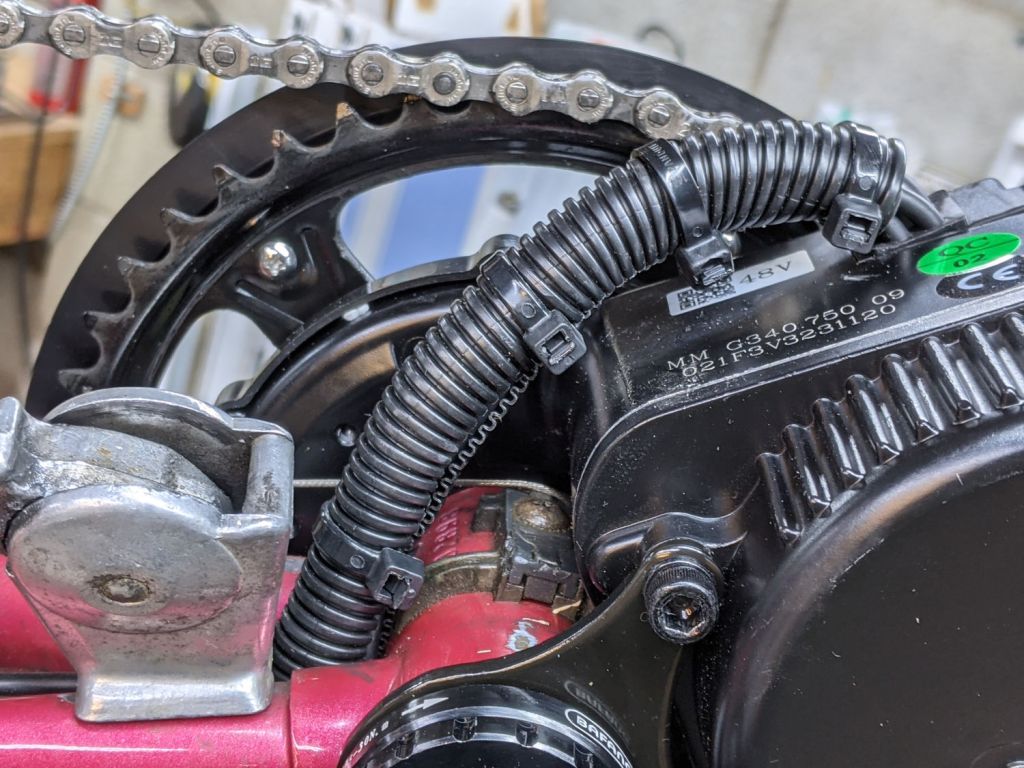
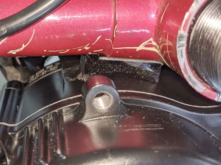
    The Bafang BBS02 runs a fat “harness cable” from the motor to the four handlebar components (two brake sensors, throttle, and display), with a lump covering the junction where the four smaller cables emerge. Securing the lump to the head tube seemed like a good way to keep the motion in the (presumably) more flexible smaller cables:

    Terry Bafang - headset cable clip - front
    Terry Bafang – headset cable clip – front

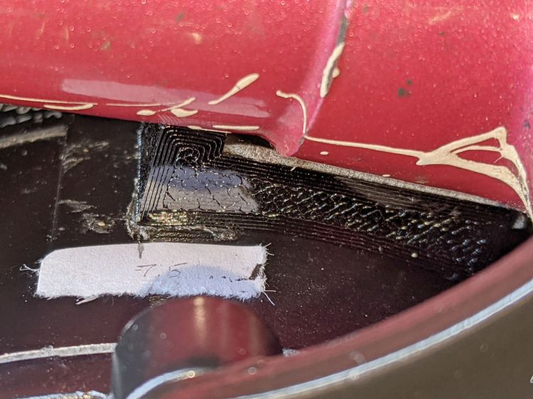
    From the rear:

    Terry Bafang - headset cable clip - rear
    Terry Bafang – headset cable clip – rear

    I later bound the four connectors into a cluster using cable ties to further reduce the clutter and keep them from tapping the top tube.

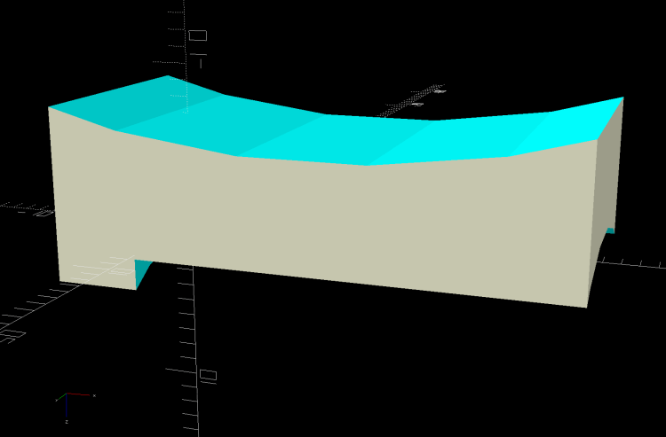
    The clip captures the cable tie in those indents:

    Terry - Bafang head tube clip - solid model
    Terry – Bafang head tube clip – solid model

    The overhangs require easy cleanup with a square file to get rid of a few droopy threads. Avoid the temptation to print it standing up as an arch, because you want the perimeter threads to go around the whole thing, not across the thinnest sections. Trust me on this.

    The OpenSCAD source code:

    module HeadClip() {
    
    CableOD = Harness[OD];
    
        difference() {
            linear_extrude(height=HeadTube[LENGTH],convexity=10)
                difference() {
                    hull() {
                        circle(d=HeadTube[ID] + 2*WallThick,$fn=FrameSides);
                        translate([0,-(HeadTube[ID] + CableOD)/2])
                            rotate(180/(FrameSides/2))
                                circle(d=CableOD + 2*WallThick,$fn=FrameSides/2);
                    }
                    circle(d=HeadTube[ID] + HoleWindage,$fn=FrameSides);
                    translate([0,-(HeadTube[ID] + CableOD)/2])
                        rotate(180/(FrameSides/2))
                            circle(d=CableOD + HoleWindage,$fn=FrameSides/2);
                    translate([0,-HeadTube[ID]/2])
                        square(0.75*CableOD,center=true);
                    translate([0,HeadTube[ID]])
                        square(2*HeadTube[ID],center=true);
                }
            translate([0,-(HeadTube[ID]/2 + CableOD + WallThick - CableTie.z/2),HeadTube[LENGTH]/2])
                cube([HeadTube[ID],CableTie.z,CableTie.y],center=true);
    
           for (i=[-1,1])
                translate([i*(HeadTube[ID]/2 + WallThick - CableTie.z/2),0,HeadTube[LENGTH]/2])
                    cube([CableTie.z,HeadTube[ID],CableTie.y],center=true);
        }
    }
    

    I briefly thought of holding two pieces together around the head tube with M3 screws, but came to my senses: a cable tie is exactly what you want when holding a cable in place. Right?

  • Bafang BBS02: Terry Cable Stop Cap

    Bafang BBS02: Terry Cable Stop Cap

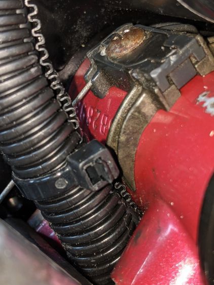
    The Terry Symmetry had shift cables running along the down tube, with cable housing stop bushings at the top:

    Terry Bafang - OEM shift stop
    Terry Bafang – OEM shift stop

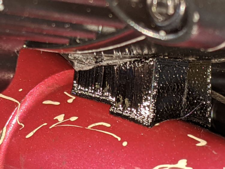
    Without the front derailleur and with the wiring harness cable on the left side, a tidy cap seemed in order:

    Terry Bafang - shift stop cap
    Terry Bafang – shift stop cap

    The oversize passage give the cable a little flex room, although that’s probably unnecessary. I reused the original M5 screw, with a washer to spread the load.

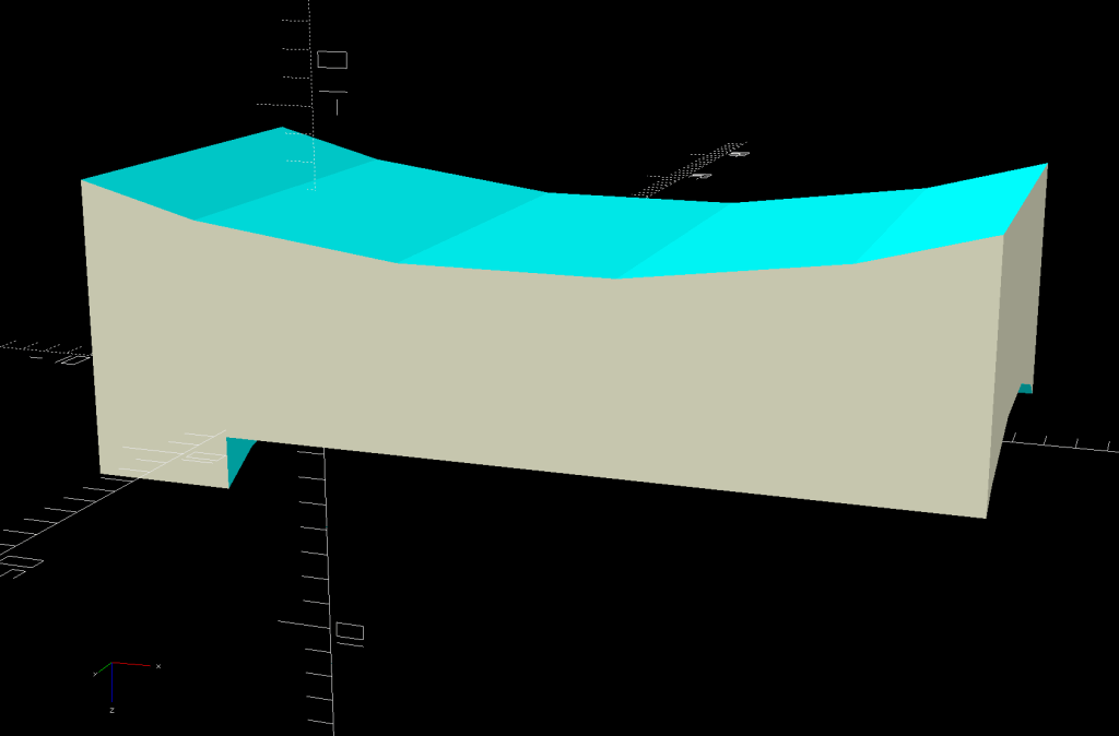
    The solid model is basically a hull around some cylinders:

    Terry - Bafang shift cap - solid model
    Terry – Bafang shift cap – solid model

    The interior matches the stud brazed onto the downtube:

    Terry - Bafang shift cap - interior - solid model
    Terry – Bafang shift cap – interior – solid model

    The only practical way to build the thing required a brim stabilizing it on the platform:

    Terry - Bafang shift cap - slice preview
    Terry – Bafang shift cap – slice preview

    My usual 0.25 mm layers came out a bit crude on the vast overhang, but 0.15 mm layers worked fine.

    The OpenSCAD source code snippet:

    CapBlock = [18,18,16.5];
    
    module ShiftCap() {
    
    Rounding = 3.5;
    CapM = 3.0;
    StudBase = [12.5,12.5,4.5];
    Stud = [5.0,9.3,15.5];
    
        difference() {
            hull() {
                translate([0,0,CapBlock.z - 0.5])
                    PolyCyl(Washer5[OD],0.5,12);
                for (i=[-1,1], j=[-1,1])
                    translate([i*(CapBlock.x/2 - Rounding),j*(CapBlock.y/2 - Rounding),0])
                        sphere(r=Rounding,$fn=12);
                translate([-CapBlock.x/2,-Harness[ID]/2 - StudBase.y/2,StudBase.z/2])
                    rotate([0,90,0])
                        cylinder(d=Harness[ID] + 2*WallThick,h=CapBlock.x,$fn=12);
            }
    
            translate([0,0,-(FrameTube.z/2 - CapM)])
                Frame();
    
            PolyCyl(Screw5[ID],2*CapBlock.z,6);
    
            PolyCyl(Stud[OD],Stud[LENGTH],12);
    
            translate([0,0,StudBase.z/2])
                cube(StudBase,center=true);
    
            translate([0,-StudBase.y/2,StudBase.z/2])
                cube(StudBase + [0,-StudBase.y/2,0],center=true);
    
           translate([-CapBlock.x,-Harness[ID]/2 - StudBase.y/2,StudBase.z/2])
                rotate([0,90,0])
                    cylinder(d=1.5*Harness[ID],h=2*CapBlock.x,$fn=12);
    
        }
    }
    

    Of course, I needed three tries to get the correct dimensions, but that’s what rapid prototyping is all about.

  • Bafang BBS02: Terry Brake Sensor

    Bafang BBS02: Terry Brake Sensor

    The old-school “aero” brake levers on Gee’s Terry Symmetry bike have rubberoid cushion covers, so I slid the Bafang brake sensors inside:

    Terry Bafang brake sensor - front
    Terry Bafang brake sensor – front

    They make the grips somewhat wider, but I can’t figure out a less destructive way of installing the things.

    I glued the magnet inside a holder contoured to fit the space available:

    Terry - Bafang brake sensor - solid model
    Terry – Bafang brake sensor – solid model

    Knocking the corners off makes it much more finger-friendly.

    It’s unobtrusive with the handle released:

    Terry Bafang brake sensor - released
    Terry Bafang brake sensor – released

    When you squeeze the lever, your fingers are nowhere near the magnet:

    Terry Bafang brake sensor - pulled
    Terry Bafang brake sensor – pulled

    The lower edge actually slides along the brake lever housing without touching, but it’s a near thing.

    Those are the same magnets I used for the Bafang brake sensors on Mary’s Tour Easy, once again aligned to aim the strongest volume of the magnetic field toward the sensor. The brake sensors activate just before the pads touch the rims and release with the magnets a few millimeters away from the sensors.

    A complete coat of JB Plastic Bonder urethane adhesive covers each magnet to both isolate it from the weather and conceal the fact that they’re recycled from a power toothbrush.

    Now that I know they work in this position, I must ease adhesive underneath the sensors so they don’t move around under normal hand pressure.

    The OpenSCAD source code snippet:

    module BrakeMagnet() {
    
        Magnet = [10.5,3.0,5.5];
        Plate = 2*ThreadThick;
        BrakeRad = 10.0;            // brake handle curve Radius
        Holder = [2*BrakeRad,7.0,Magnet.z + Plate];
    
    
        difference() {
            intersection() {
                translate([0,-BrakeRad,0])
                    rotate(180/24)
                        cylinder(r=BrakeRad,h=Holder.z,$fn=24);
                translate([0,BrakeRad - Holder.y,Holder.z/2])
                    cube([2*BrakeRad,2*BrakeRad,Holder.z],center=true);
                translate([0,0,-2*BrakeRad/sqrt(2) + Holder.z - 3.0 + BrakeRad])
                    rotate([0,45,0])
                        cube(2*[BrakeRad,2*BrakeRad,BrakeRad],center=true);
            }
            translate([0,Magnet.y/2 - Holder.y - Protrusion/2,Magnet.z/2 + Plate + Protrusion/2])
                cube(Magnet + [0,Protrusion,Protrusion],center=true);
        }
    
    }
    

  • Bafang BBS02: Speed Sensor Alignment

    Bafang BBS02: Speed Sensor Alignment

    My friend Gee’s bike is a Terry Symmetry, designed for (small) women, which poses challenges when mounting “normal size” components. The Bafang BBS02 speed sensor mount (with a reshaped nut) requires far more clearance between the chainstay and the wheel spokes than the Symmetry has:

    Bafang BBS02 Speed Sensor - OEM bracket
    Bafang BBS02 Speed Sensor – OEM bracket

    The chainstay is nearly parallel to the spokes, so the sensor fits equally poorly anywhere its cable will allow.

    The obvious solution is to reverse the mount and stick it to the outside of the chainstay, but it’s not mmmm symmetric: the other end is closed. Use a pull saw to cut off the closed end, stick the sensor post in the other way, and then it fits fine:

    Bafang BBS02 Speed Sensor - reversed bracket - top
    Bafang BBS02 Speed Sensor – reversed bracket – top

    The sawed-off mount is visible from below:

    Bafang BBS02 Speed Sensor - reversed bracket - bottom
    Bafang BBS02 Speed Sensor – reversed bracket – bottom

    It looks fine from the outside:

    Bafang BBS02 Speed Sensor - reversed bracket - left side
    PXL_20210620_160950653 – Bafang BBS02 Speed Sensor – reversed bracket – left side

    Mad props to Bafang for the LED showing when the magnet is properly positioned.

  • Bafang BBS02: Drop-bar Throttle Adapter

    Bafang BBS02: Drop-bar Throttle Adapter

    The Bafang BBS02 package includes a thumb-activated throttle which, like the display, should clamp onto a 22.2 mm handlebar. The one on Mary’s bike fit neatly at the end of the left handgrip:

    Tour Easy grips - left installed
    Tour Easy grips – left installed

    There’s no similar location on a drop-bar bike that doesn’t get in the way, particularly on my friend Gee’s bike with narrow bars.

    With a display handlebar adapter in hand, this seemed less awful than anything else I had in mind:

    Bafang Throttle adapter - front view
    Bafang Throttle adapter – front view

    That’s the front view, so it’s on the right side in front of the handlebar. I think it’s usable with either a thumb or fingertips from a hand on the top of the bar. The handlebar lacks tape, as mounting the brake sensors poses a challenge.

    The view from the rear isn’t too revealing:

    Bafang Throttle adapter - rear view
    Bafang Throttle adapter – rear view

    Not too unsightly, but definitely not a standard setup!

  • Bafang BBS02: Drop-bar Display Adapter

    Bafang BBS02: Drop-bar Display Adapter

    All of the Bafang BBS02 displays have a compression clamp intended for more-or-less standard 22.2 mm handlebars, as found on typical upright BMX-ish bikes suitable for conversion to e-bikes and, oddly, our Tour Easy recumbents. My friend’s bike has drop-bar handlebars with a 25.4 mm (yes, exactly 1 inch) center section that just isn’t going to fit through that hole.

    The least awful solution involved summoning an adapter from the vasty digital deep:

    Display adapter mount - solid model
    Display adapter mount – solid model

    The hole clamps around the handlebar with an M3 SHCS pulling it snug and the display clamps around the peg to hold everything together:

    Bafang Display adapter - front view
    Bafang Display adapter – front view

    There’s not much to see from the side:

    Bafang Display adapter - left view
    Bafang Display adapter – left view

    Those scuffs arrived on the protective plastic film!

    The OpenSCAD source code includes some cruft from an idea that didn’t work out quite right:

    HandlebarMax = 1*inch;                      // middle handlebar diameter
    HandlebarMin = 24.0;                        //  .. tape section
    
    BafangClampID = 22.3;                       // new handlebar diameter
    
    
    … snippage …
    
    // Handlebar mount for controller
    
    module DispMount() {
    
    ClampRing = [HandlebarMax,HandlebarMax + 2*WallThick,10.0];
    ClampOffset = (HandlebarMax + BafangClampID)/2 + 6.0;
    
    DispStudLenth = 16.5;
    
    NumSides = 24;
    
    Tilt = 0*atan2((ClampRing[OD] - BafangClampID)/2,ClampOffset);
    echo(str("Tilt: ",Tilt));
    
        difference() {
            union() {
                hull() {
                    cylinder(d=ClampRing[OD],h=ClampRing[LENGTH],$fn=NumSides);
                    translate([0,ClampOffset,0])
                        cylinder(d=BafangClampID,h=ClampRing[LENGTH],$fn=NumSides);
                }
                translate([0,ClampOffset,0])
                    cylinder(d=BafangClampID,h=ClampRing[LENGTH] + DispStudLenth,$fn=NumSides);
                translate([-ClampRing[ID]/4,-(ClampRing[OD]/2),ClampRing[LENGTH]/2])
                    rotate([0,90,0]) rotate(180/8)
                        cylinder(d=ClampRing[LENGTH]/cos(180/8),h=ClampRing[ID]/2,$fn=8);
            }
            cube([Kerf,4*ClampOffset,4*DispStudLenth],center=true);
            translate([0,0,-Protrusion])
                cylinder(d=ClampRing[ID],h=ClampRing[LENGTH] + 2*Protrusion,$fn=NumSides);
            translate([-ClampRing[ID]/2,-(ClampRing[OD]/2),ClampRing[LENGTH]/2])
                rotate([0,90,0]) rotate(180/8)
                    PolyCyl(Screw3[ID],ClampRing[ID],8);
            for (i=[-1,1])
                translate([i*ClampRing[ID]/4,-(ClampRing[OD]/2),ClampRing[LENGTH]/2])
                    rotate([0,i*90,0]) rotate(180/8)
                        PolyCyl(Washer3[OD],ClampRing[ID],$fn=8);
    
            translate([-5,25,EmbossDepth/2 - Protrusion/2])
                rotate(Tilt)
                    cube([4.5,21.5,EmbossDepth + Protrusion],center=true);
    
        }
    
        translate([-5,25,0])
            linear_extrude(height=EmbossDepth)
                rotate(90 + Tilt) mirror([0,1,0])
                  text(text="KE4ZNU",size=3.3,spacing=1.05,font="Bitstream Vera Sans:style=Bold",
                       halign="center",valign="center");
    
    }
    

    It’s rock-solid stable: pushing the buttons doesn’t budge it in the least.

  • Stylus Tip Restaking

    Stylus Tip Restaking

    The tip of the much-battered stylus useful for websites presenting tiny phone-hostile buttons appeared in the laundry basket, narrowly avoiding a trip through the washer. The shell’s original all-around swaging had evidently loosened enough to release the tip, so I applied a hammer and punch:

    Screen stylus tip restaking
    Screen stylus tip restaking

    The punch mark (with another on the opposite side) is barely visible, but holds the tip securely in place. Next time I may need more hammer.