|
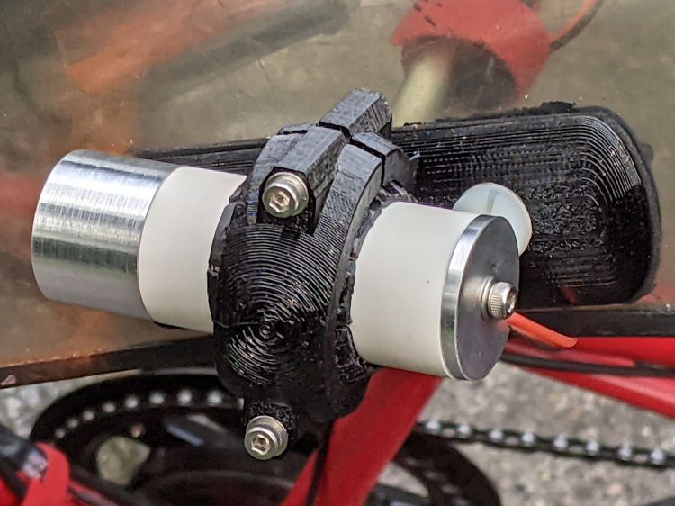
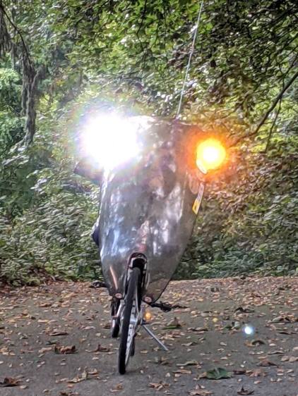
// Tour Easy Fairing Flashlight Mount |
|
// Ed Nisley KE4ZNU – July 2017 |
|
// August 2017 – |
|
// August 2020 – add reinforcing columns under mount cradle |
|
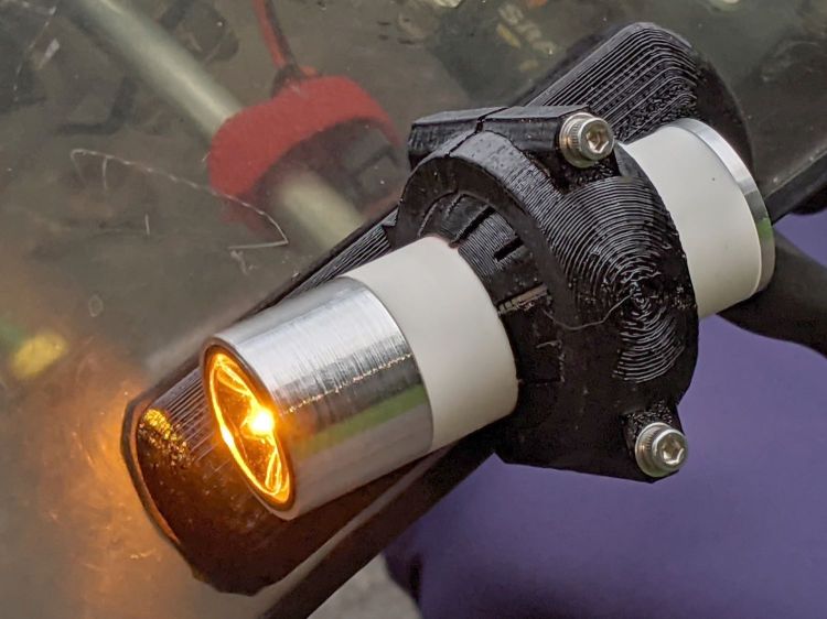
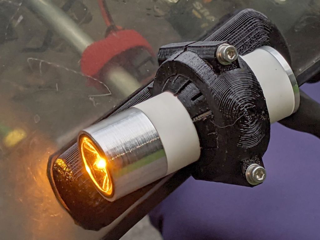
// August 2021 – 1 W Amber LED |
|
|
|
/* [Build Options] */ |
|
|
|
FlashName = "1WLED"; // [AnkerLC40,AnkerLC90,J5TactV2,InnovaX5,Sidemarker,Clearance,Laser,1WLED] |
|
|
|
Component = "BallClamp"; // [Ball, BallClamp, Mount, Plates, Bracket, Complete] |
|
|
|
Layout = "Build"; // [Build, Show] |
|
|
|
Support = true; |
|
|
|
MountSupport = true; |
|
|
|
/* [Hidden] */ |
|
|
|
ThreadThick = 0.25; // [0.20, 0.25] |
|
ThreadWidth = 0.40; // [0.40] |
|
|
|
function IntegerMultiple(Size,Unit) = Unit * ceil(Size / Unit); |
|
|
|
Protrusion = 0.01; // [0.01, 0.1] |
|
|
|
HoleWindage = 0.2; |
|
|
|
/* [Fairing Mount] */ |
|
|
|
Side = "Right"; // [Right,Left] |
|
|
|
ToeIn = -10; // inward from ahead |
|
Tilt = 20; // upward from forward (M=20 E=10) |
|
Roll = 0; // outward from top |
|
|
|
//- Screws and inserts |
|
|
|
/* [Hidden] */ |
|
|
|
ID = 0; |
|
OD = 1; |
|
LENGTH = 2; |
|
|
|
/* [Hidden] */ |
|
|
|
ClampInsert = [3.0,4.2,8.0]; |
|
|
|
ClampScrew = [3.0,5.9,35.0]; // thread dia, head OD, screw length |
|
ClampScrewWasher = [3.0,6.75,0.5]; |
|
ClampScrewNut = [3.0,6.1,4.0]; // nyloc nut |
|
|
|
/* [Hidden] */ |
|
|
|
F_NAME = 0; |
|
F_GRIPOD = 1; |
|
F_GRIPLEN = 2; |
|
|
|
LightBodies = [ |
|
["AnkerLC90",26.6,48.0], |
|
["AnkerLC40",26.6,55.0], |
|
["J5TactV2",25.0,30.0], |
|
["InnovaX5",22.0,55.0], |
|
["Sidemarker",15.0,20.0], |
|
["Clearance",50.0,20.0], |
|
["Laser",10.0,30.0], |
|
["1WLED",25.4,40.0], |
|
]; |
|
|
|
//- Fairing Bracket |
|
// Magic numbers taken from the actual fairing mount |
|
|
|
/* [Hidden] */ |
|
|
|
inch = 25.4; |
|
|
|
BracketHoleOD = 0.25 * inch; // 1/4-20 bolt holes |
|
|
|
BracketHoleOC = 1.0 * inch; // fairing hole spacing |
|
// usually 1 inch, but 15/16 on one fairing |
|
|
|
Bracket = [48.0,16.3,3.6 – 0.6]; // fairing bracket end plate overall size |
|
BracketHoleOffset = (3/8) * inch; // end to hole center |
|
|
|
BracketM = 3.0; // endcap arc height |
|
BracketR = (pow(BracketM,2) + pow(Bracket[1],2)/4) / (2*BracketM); // … radius |
|
|
|
//- Base plate dimensions |
|
|
|
Plate = [100.0,30.0,6*ThreadThick + Bracket[2]]; |
|
PlateRad = Plate[1]/4; |
|
|
|
RoundEnds = true; |
|
|
|
echo(str("Base plate thick: ",Plate[2])); |
|
|
|
//- Select flashlight data from table |
|
|
|
echo(str("Flashlight: ",FlashName)); |
|
FlashIndex = search([FlashName],LightBodies,1,0)[F_NAME]; |
|
|
|
//- Set ball dimensions |
|
|
|
BallWall = 5.0; // max ball wall thickness |
|
echo(str("Ball wall: ",BallWall)); |
|
|
|
BallOD = IntegerMultiple(LightBodies[FlashIndex][F_GRIPOD] + 2*BallWall,1.0); |
|
echo(str(" OD: ",BallOD)); |
|
|
|
BallLength = IntegerMultiple(min(sqrt(pow(BallOD,2) – pow(LightBodies[FlashIndex][F_GRIPOD],2)) – 2*4*ThreadThick, |
|
LightBodies[FlashIndex][F_GRIPLEN]),1.0); |
|
echo(str(" length: ",BallLength)); |
|
|
|
BallSides = 8*4; |
|
|
|
//- Set clamp ring dimensions |
|
|
|
//ClampOD = 50; |
|
ClampOD = BallOD + 2*5; |
|
echo(str("Clamp OD: ",ClampOD)); |
|
|
|
ClampLength = min(20.0,0.75*BallLength); |
|
echo(str(" length: ",ClampLength)); |
|
|
|
ClampScrewOC = IntegerMultiple((ClampOD + BallOD)/2,1); |
|
echo(str(" screw OC: ",ClampScrewOC)); |
|
|
|
TiltMirror = (Side == "Right") ? [0,0,0] : [0,1,0]; |
|
|
|
//- Adjust hole diameter to make the size come out right |
|
|
|
module PolyCyl(Dia,Height,ForceSides=0) { // based on nophead's polyholes |
|
Sides = (ForceSides != 0) ? ForceSides : (ceil(Dia) + 2); |
|
FixDia = Dia / cos(180/Sides); |
|
cylinder(r=(FixDia + HoleWindage)/2,h=Height,$fn=Sides); |
|
} |
|
|
|
//- Fairing Bracket |
|
// This part of the fairing mount supports the whole flashlight mount |
|
// Centered on screw hole |
|
|
|
module Bracket() { |
|
|
|
linear_extrude(height=Bracket[2],convexity=2) |
|
difference() { |
|
translate([(Bracket[0]/2 – BracketHoleOffset),0,0]) |
|
offset(delta=ThreadWidth) |
|
intersection() { |
|
square([Bracket[0],Bracket[1]],center=true); |
|
union() { |
|
for (i=[-1,0,1]) // middle circle fills gap |
|
translate([i*(Bracket[0]/2 – BracketR),0]) |
|
circle(r=BracketR); |
|
} |
|
} |
|
circle(d=BracketHoleOD/cos(180/8),$fn=8); // dead center at the origin |
|
} |
|
} |
|
|
|
//- General plate shape |
|
// Centered in the middle of the plate |
|
|
|
module PlateBlank() { |
|
|
|
difference() { |
|
intersection() { |
|
translate([0,0,Plate[2]/2]) // select upper half of spheres |
|
cube(Plate,center=true); |
|
hull() |
|
if (RoundEnds) |
|
for (i=[-1,1]) |
|
translate([i*(Plate[0]/2 – PlateRad),0,0]) |
|
resize([Plate[1]/2,Plate[1],2*Plate[2]]) |
|
sphere(r=PlateRad); // nice round ends! |
|
else |
|
for (i=[-1,1], j=[-1,1]) |
|
translate([i*(Plate[0]/2 – PlateRad),j*(Plate[1]/2 – PlateRad),0]) |
|
resize([2*PlateRad,2*PlateRad,2*Plate[2]]) |
|
sphere(r=PlateRad); // nice round corners! |
|
} |
|
translate([BracketHoleOC,0,-Protrusion]) // punch screw holes |
|
PolyCyl(BracketHoleOD,2*Plate[2],8); |
|
translate([-BracketHoleOC,0,-Protrusion]) |
|
PolyCyl(BracketHoleOD,2*Plate[2],8); |
|
} |
|
} |
|
|
|
//- Inner plate |
|
|
|
module InnerPlate() { |
|
|
|
difference() { |
|
PlateBlank(); |
|
translate([-BracketHoleOC,0,Plate[2] – Bracket[2] + Protrusion]) // punch fairing bracket |
|
Bracket(); |
|
} |
|
} |
|
|
|
//- Outer plate |
|
// With optional legend for orientation and parameters |
|
|
|
module OuterPlate(Legend = true) { |
|
|
|
TextRotate = (Side == "Left") ? 0 : 180; |
|
|
|
difference() { |
|
PlateBlank(); |
|
if (Legend) |
|
mirror([0,1,0]) |
|
translate([0,0,-Protrusion]) |
|
linear_extrude(height=3*ThreadThick + Protrusion) { |
|
translate([BracketHoleOC + 15,0,0]) |
|
text(text=">>>",size=5,spacing=1.20,font="Arial",halign="center",valign="center"); |
|
translate([-BracketHoleOC,8,0]) rotate(TextRotate) |
|
text(text=str("Toe ",ToeIn),size=5,spacing=1.20,font="Arial",halign="center",valign="center"); |
|
translate([-BracketHoleOC,-8,0]) rotate(TextRotate) |
|
text(text=str("Tilt ",Tilt),size=5,spacing=1.20,font="Arial",halign="center",valign="center"); |
|
translate([BracketHoleOC,-8,0]) rotate(TextRotate) |
|
text(text=Side,size=5,spacing=1.20,font="Arial",halign="center",valign="center"); |
|
translate([BracketHoleOC,8,0]) rotate(TextRotate) |
|
text(text=str("Roll ",Roll),size=5,spacing=1.20,font="Arial",halign="center",valign="center"); |
|
translate([0,0,0]) |
|
rotate(90) |
|
text(text="KE4ZNU",size=4,spacing=1.20,font="Arial",halign="center",valign="center"); |
|
} |
|
} |
|
} |
|
|
|
//- Slotted ball around flashlight |
|
// Print with brim to ensure adhesion! |
|
|
|
module SlotBall() { |
|
|
|
NumSlots = 8*2; // must be even, half cut from each end |
|
SlotWidth = 2*ThreadWidth; |
|
SlotBaseThick = 10*ThreadThick; // enough to hold finger ends together |
|
RibLength = (BallOD – LightBodies[FlashIndex][F_GRIPOD])/2; |
|
|
|
translate([0,0,(Layout == "Build") ? BallLength/2 : 0]) |
|
rotate([0,(Layout == "Show") ? 90 : 0,0]) |
|
difference() { |
|
intersection() { |
|
sphere(d=BallOD,$fn=2*BallSides); // basic ball |
|
cube([2*BallOD,2*BallOD,BallLength],center=true); // trim to length |
|
} |
|
translate([0,0,-LightBodies[FlashIndex][F_GRIPOD]]) |
|
rotate(180/BallSides) |
|
PolyCyl(LightBodies[FlashIndex][F_GRIPOD],2*BallOD,BallSides); // remove flashlight body |
|
|
|
for (i=[0:NumSlots/2 – 1]) { // cut slots |
|
a=i*(2*360/NumSlots); |
|
SlotCutterLength = LightBodies[FlashIndex][F_GRIPOD]; |
|
rotate(a) |
|
translate([SlotCutterLength/2,0,SlotBaseThick]) |
|
cube([SlotCutterLength,SlotWidth,BallLength],center=true); |
|
rotate(a + 360/NumSlots) |
|
translate([SlotCutterLength/2,0,-SlotBaseThick]) |
|
cube([SlotCutterLength,SlotWidth,BallLength],center=true); |
|
} |
|
} |
|
|
|
color("Yellow") |
|
if (Support && (Layout == "Build")) { |
|
for (i=[0:NumSlots-1]) { |
|
a = i*360/NumSlots; |
|
rotate(a + 180/NumSlots) |
|
translate([(LightBodies[FlashIndex][F_GRIPOD] + RibLength)/2 + ThreadWidth,0,BallLength/(2*4)]) |
|
cube([RibLength,2*ThreadWidth,BallLength/4],center=true); |
|
} |
|
} |
|
} |
|
|
|
//- Clamp around flashlight ball |
|
|
|
BossLength = ClampScrew[LENGTH] – 1*ClampScrewWasher[LENGTH]; |
|
BossOD = ClampInsert[OD] + 2*(6*ThreadWidth); |
|
|
|
module BallClamp(Section="All") { |
|
|
|
difference() { |
|
union() { |
|
intersection() { |
|
sphere(d=ClampOD,$fn=BallSides); // exterior ball clamp |
|
cube([ClampLength,2*ClampOD,2*ClampOD],center=true); // aiming allowance |
|
} |
|
hull() |
|
for (j=[-1,1]) |
|
translate([0,j*ClampScrewOC/2,-BossLength/2]) |
|
cylinder(d=BossOD,h=BossLength,$fn=6); |
|
} |
|
|
|
sphere(d=(BallOD + 1*ThreadThick),$fn=BallSides); // interior ball with minimal clearance |
|
|
|
for (j=[-1,1]) { |
|
translate([0,j*ClampScrewOC/2,-ClampOD]) // screw clearance |
|
PolyCyl(ClampScrew[ID],2*ClampOD,6); |
|
translate([0,j*ClampScrewOC/2, // insert clearance |
|
-0*(BossLength/2 – ClampInsert[LENGTH] – 3*ThreadThick) + Protrusion]) |
|
rotate([0,180,0]) |
|
PolyCyl(ClampInsert[OD],2*ClampOD,6); |
|
translate([0,j*ClampScrewOC/2, // insert transition |
|
-(BossLength/2 – ClampInsert[LENGTH] – 3*ThreadThick)]) |
|
cylinder(d1=ClampInsert[OD]/cos(180/6),d2=ClampScrew[ID],h=6*ThreadThick,$fn=6); |
|
} |
|
|
|
if (Section == "Top") |
|
translate([0,0,-ClampOD/2]) |
|
cube([2*ClampOD,2*ClampOD,ClampOD],center=true); |
|
else if (Section == "Bottom") |
|
translate([0,0,ClampOD/2]) |
|
cube([2*ClampOD,2*ClampOD,ClampOD],center=true); |
|
} |
|
|
|
color("Yellow") |
|
if (Support) { // ad-hoc supports |
|
NumRibs = 6; |
|
RibLength = 0.5 * BallOD; |
|
RibWidth = 1.9*ThreadWidth; |
|
SupportOC = ClampLength / NumRibs; |
|
|
|
if (Section == "Top") // base plate for adhesion |
|
translate([0,0,ThreadThick]) |
|
cube([ClampLength + 6*ThreadWidth,RibLength,2*ThreadThick],center=true); |
|
else if (Section == "Bottom") |
|
translate([0,0,-ThreadThick]) |
|
cube([ClampLength + 6*ThreadWidth,RibLength,2*ThreadThick],center=true); |
|
|
|
render(convexity=2*NumRibs) |
|
intersection() { |
|
sphere(d=BallOD – 0*ThreadWidth); // cut at inner sphere OD |
|
|
|
cube([ClampLength + 2*ThreadWidth,RibLength,BallOD],center=true); |
|
|
|
if (Section == "Top") // select only desired section |
|
translate([0,0,ClampOD/2]) |
|
cube([2*ClampOD,2*ClampOD,ClampOD],center=true); |
|
else if (Section == "Bottom") |
|
translate([0,0,-ClampOD/2]) |
|
cube([2*ClampOD,2*ClampOD,ClampOD],center=true); |
|
|
|
union() { // ribs for E-Z build |
|
for (j=[-1,0,1]) |
|
translate([0,j*SupportOC,0]) |
|
cube([ClampLength,RibWidth,1.0*BallOD],center=true); |
|
for (i=[0:NumRibs]) // allow NumRibs + 1 to fill the far end |
|
translate([i*SupportOC – ClampLength/2,0,0]) |
|
rotate([0,90,0]) |
|
cylinder(d=BallOD – 2*ThreadThick, |
|
h=RibWidth,$fn=BallSides,center=true); |
|
} |
|
} |
|
} |
|
} |
|
|
|
//- Mount between fairing plate and flashlight ball |
|
// Build with support for bottom of clamp screws! |
|
|
|
module Mount() { |
|
|
|
MountShift = [ClampOD*sin(ToeIn/2),0,ClampOD/2]; |
|
|
|
OuterPlate(); |
|
|
|
mirror(TiltMirror) { |
|
intersection() { |
|
translate(MountShift) |
|
rotate([-Roll,ToeIn,Tilt]) |
|
BallClamp("Bottom"); |
|
translate([0,0,Plate.x/2 + 3*ThreadThick]) |
|
cube(Plate.x,center=true); |
|
} |
|
|
|
if (MountSupport) // anchor outer corners at worst overhang |
|
color("Yellow") { |
|
RibWidth = 1.9*ThreadWidth; |
|
SupportOC = 0.1 * ClampLength; |
|
intersection() { |
|
difference() { |
|
rotate([0,0,Tilt]) |
|
translate([(ClampOD – BallOD)*sin(ToeIn/2),0,3*ThreadThick]) // Z = avoid legends |
|
for (i=[-4.5,-2.5,0,2.0,4.5]) |
|
translate([i*SupportOC – 0.0,0,(5 + Plate[2])/2]) |
|
cube([RibWidth,0.7*ClampOD,(5 + Plate[2])],center=true); |
|
translate(MountShift) |
|
rotate([-Roll,ToeIn,Tilt]) |
|
sphere(d=ClampOD – 2*ThreadWidth,$fn=BallSides); |
|
} |
|
translate([0,0,ClampOD/2]) |
|
cube([Plate.x,Plate.y,ClampOD],center=true); |
|
} |
|
} |
|
} |
|
} |
|
|
|
//- Build things |
|
|
|
if (Component == "Bracket") |
|
Bracket(); |
|
|
|
if (Component == "Ball") |
|
SlotBall(); |
|
|
|
if (Component == "BallClamp") |
|
if (Layout == "Show") |
|
BallClamp("All"); |
|
else if (Layout == "Build") |
|
BallClamp("Top"); |
|
|
|
if (Component == "Mount") |
|
Mount(); |
|
|
|
if (Component == "Plates") { |
|
translate([0,0.7*Plate[1],0]) |
|
InnerPlate(); |
|
translate([0,-0.7*Plate[1],0]) |
|
OuterPlate(Legend = false); |
|
} |
|
|
|
if (Component == "Complete") { |
|
OuterPlate(); |
|
mirror(TiltMirror) { |
|
translate([0,0,ClampOD/2 + BossOD*abs(sin(ToeIn))]) { |
|
rotate([-Roll,ToeIn,Tilt]) |
|
SlotBall(); |
|
rotate([-Roll,ToeIn,Tilt]) |
|
BallClamp(); |
|
} |
|
} |
|
} |