Ed Nisley's Blog: Shop notes, electronics, firmware, machinery, 3D printing, laser cuttery, and curiosities. Contents: 100% human thinking, 0% AI slop.
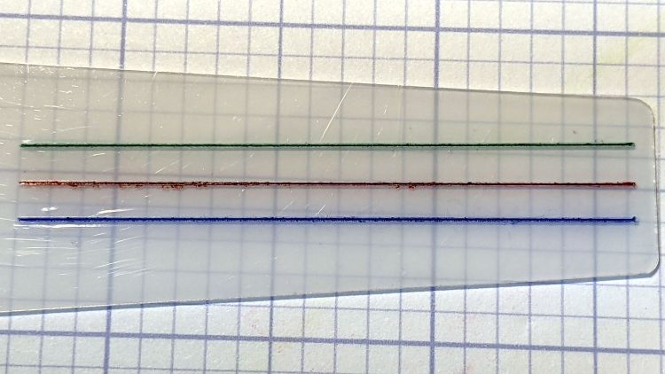
All three hairlines have 0.3 mm depth of cut, with the spindle running at 10 kRPM and the cut proceeding at 24 inch/min = 600 mm/min. All three cuts went through a strip of water + detergent along their length, which seems to work perfectly.
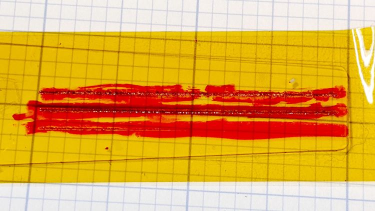
The cuts start on the left side:
Hairline V tool tests – 0.3 mm 10 kRPM 24 ipm – start
I cut the red hairline through the PET cursor’s protective film to confirm doing it that way is a Bad Idea™; the gnarly appearance is sufficient proof.
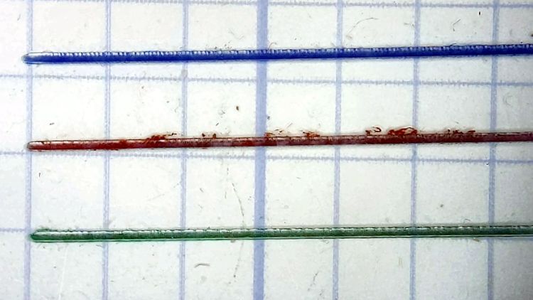
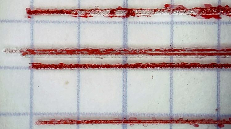
The cuts end on the right:
Hairline V tool tests – 0.3 mm 10 kRPM 24 ipm – end
Eyeballometrically, the cuts are the same depth on both ends, with a slight texture difference at the start as the X axis ramps up to full speed.
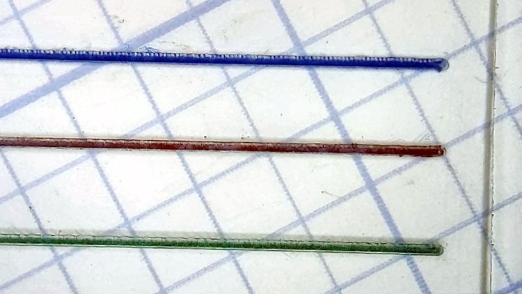
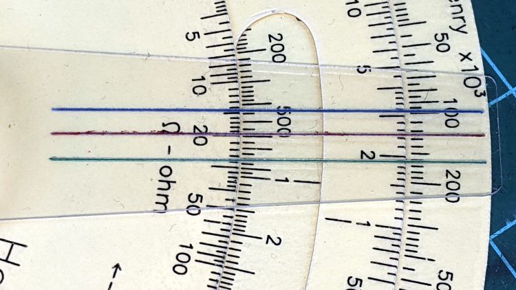
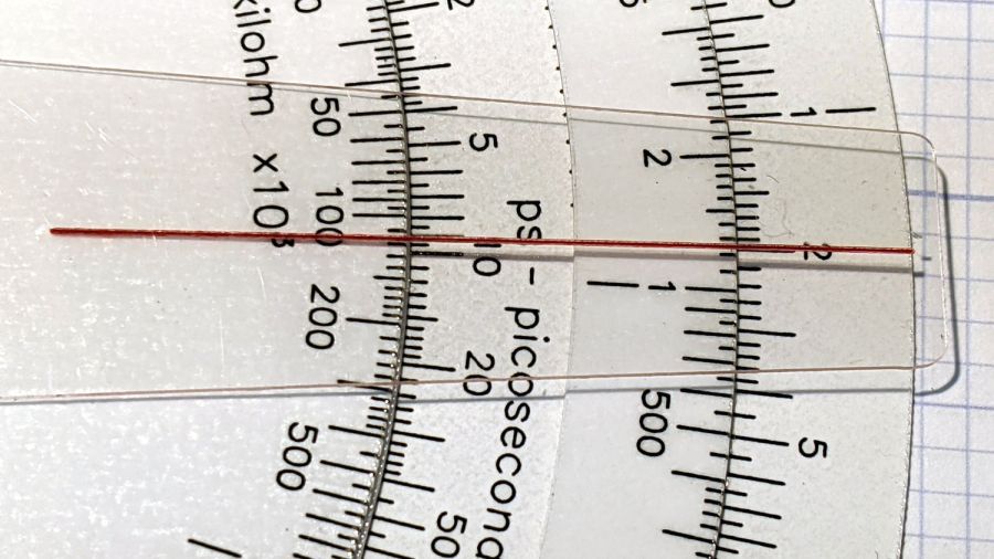
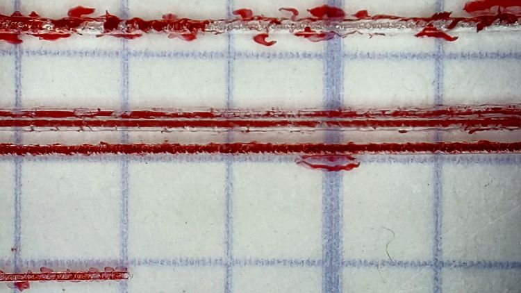
They’d be a bit stout on an old-school engraved slide rule, but look just fine laid against a laser-printed Homage Tek Circuit Computer:
Hairline V tool tests – 0.3 mm 10 kRPM 24 ipm – Tek CC
Flushed with success, here’s a fresh-cut red hairline in action:
Tek CC cursor hairline – V tool red fill
The end of the cursor sticks out 1 mm over the rim of the bottom deck, because I wanted to find out whether that would make it easier to move. It turns out the good folks at Tek knew what they were doing; a too-long cursor buckles too easily.
The trick will be touching off the V tool accurately enough on the cursor surface to get the correct depth of cut. The classic machinist’s technique involves a pack of rolling papers, which might be coming back into fashion here in NY.
Hairline V tool – 0.2 0.3 0.4 DOC 10K RPM – water cool mid
The bottom blue hairline started with a good cut and ended with the V tool skating along the surface without cutting. The raggedy red one just above it is what happens when you (well, I) try engraving a hairline through Kapton tape without coolant; just don’t do that thing.
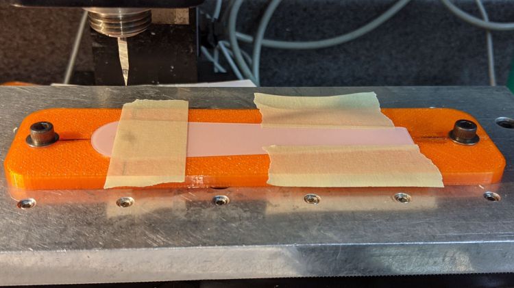
The 3D printed fixture holding the cursor came from a neurotically aligned Makergear M2 and the tooling plate has never had much attention to its alignment, so I figured the tilt probably came from crud between the tooling plate and the Sherline’s X axis table, with the printed fixture contributing zilch to the problem.
Which turned out to be the case. Scraping a few flakes from the bottom of the plate and top of the table, dissolving old crud with water + alcohol, and passing a file over both surfaces definitely made a difference. I converted a sheet of 0.1 mm laminating plastic film into a pad by punching holes for the T-nuts:
Sherline tooling plate pad
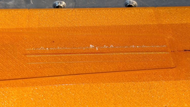
Snugging the tooling plate down produced perfect alignment along the length of three 0.3 mm deep hairlines:
That’s the fixture intended for Gyros circular saw blades, repurposed for V tool engraving. The V tool in the Sherline tool holder collet is one of the ten-pack from the CNC 3018, unused until this adventure.
The actual setup had a scrap cursor secured with a strip of Kapton tape:
Those are three passes at (nominal) depths of 0.2, 0.3, and 0.4 mm (bottom to top) with a pre-existing hairline visible just above the second pass. The spindle ran at the Sherline’s top speed of just under 10 kRPM with no coolant on the workpiece.
I touched off the 0.2 mm cut by lowering the tool 0.1 mm at a time until it just left a mark on the Kapton tape, after a coarse touch-off atop a 0.5 mm plastic card, and calling it zero.
Scribbling over the cuts with a red Industrial Sharpie looked downright gory:
The top hairline shows distinct signs of melted PET plastic along the trench, with poor color fill due to the Sharpie not sticking to / wiping off the smooth-ish trench bottom. The next one is the existing saw-cut hairline with the lead-in cut over on the left.
The 0.3 and 0.2 mm hairlines look much better, with less debris and more complete fill. Unfortunately, the right side of the Sherline’s tooling plate seems to be a few tenths of a millimeter lower than the left, causing the 0.2 mm hairline to … disappear … where the cutter skipped up onto the Kapton tape:
Now, in practical terms, this is the first time I’ve actually needed platform alignment to within a hundred microns in subtractive machining. As some folks discover to their astonishment, however, 3D printing does require that level of accuracy:
Thinwall Box – platform height
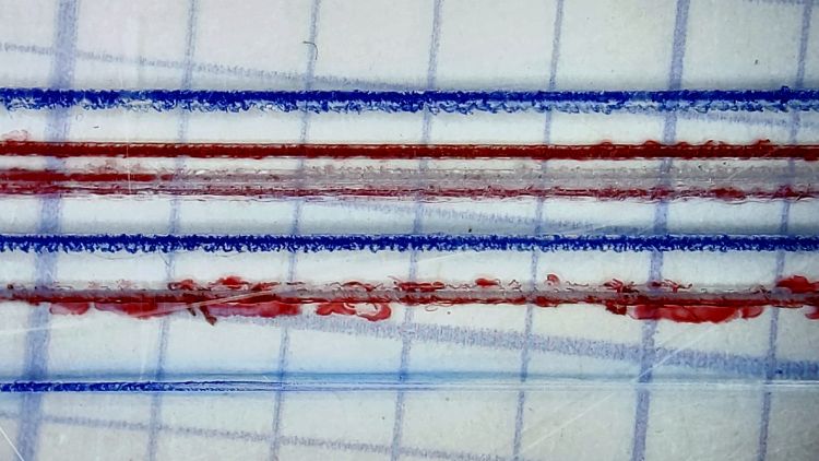
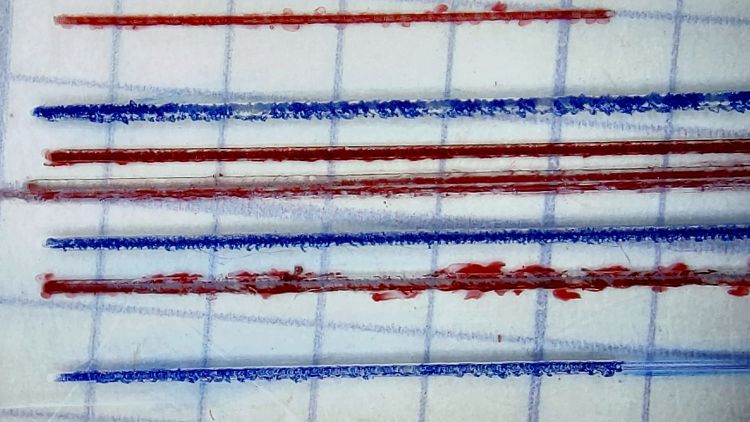
Engraving through a layer of tape isn’t the right way to do it and some coolant will definitely improve the results, so I ignored the alignment issue, remounted the same scrap cursor with the red hairlines on the bottom, pulled a strip of water + detergent along the tool path, cut the same hairlines, and colored the trenches with blue Industrial Sharpie:
Hairline V tool – 0.2 0.3 0.4 DOC 10K RPM – water cool start
The 0.2 mm hairline on the bottom becomes a line as the V bit begins sliding along the surface at 10 kRPM without cutting:
Hairline V tool – 0.2 0.3 0.4 DOC 10K RPM – water cool mid
The 0.3 mm hairline looks pretty good and the 0.4 mm hairline remains too rugged by the end of the passes. I think the actual depth of cut is at least 0.05 mm less than at the start:
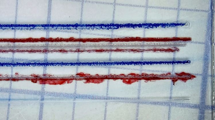
Hairline V tool – 0.2 0.3 0.4 DOC 10K RPM – water cool end
Obviously, neurotically precise touchoff carries a big reward, as will aligning the tooling plate to an absurd degree.
A real machinist simply flycuts the top of an offending part / fixture / tooling plate to align it with the machine’s spindle, but I have a sneaky suspicion the real problem is a speck (or ten) of swarf between the Sherline’s table and the tooling plate; better cleanliness and attention to detail may improve the situation.
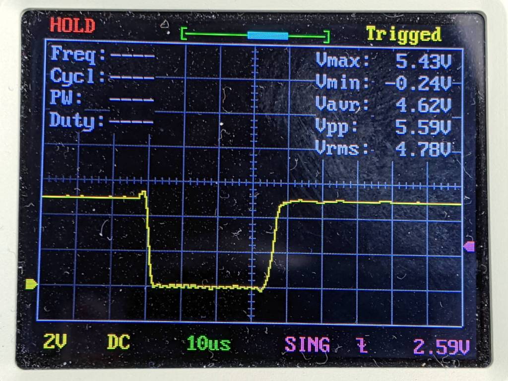
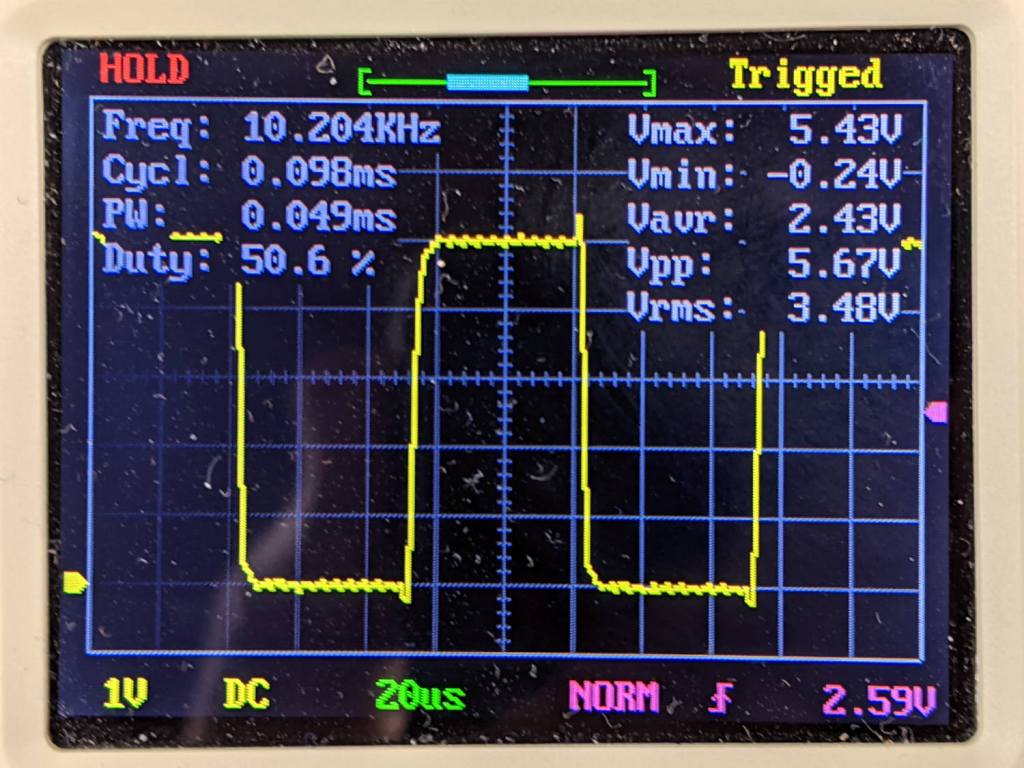
Long long ago, as part of tidying up the power distribution inside the Sherline CNC controller PCB, I wrote a cleanroom reimplementation of its PIC firmware and settled on a 25 µs Step pulse width with a minimum 50 µs period:
After thrashing through enough of the Kicad-to-HAL converter to get a HAL file sufficiently tasty to prevent LinuxCNC from spitting it out, the X and A axes moved with a gritty sound and the two other axes were pretty much inert.
After eliminating everything else, including having Tiny Scope™ confirm the pulses were exactly the right duration, I increased them by 10 µs:
After which, all the axes suddenly worked perfectly.
At some point along the way, I (re)discovered that Sherline Step pulses are active-low, although in practical terms getting the pulse upside-down just delays the active edge by its width. Given that the Sherline’s top speed is 24 inch/min = 0.4 inch/s, the minimum step period is 156 µs and even a wrong-polarity step should work fine.
For the record, here’s a perfectly good Step pulse:
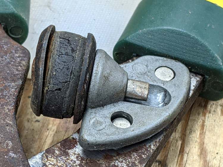
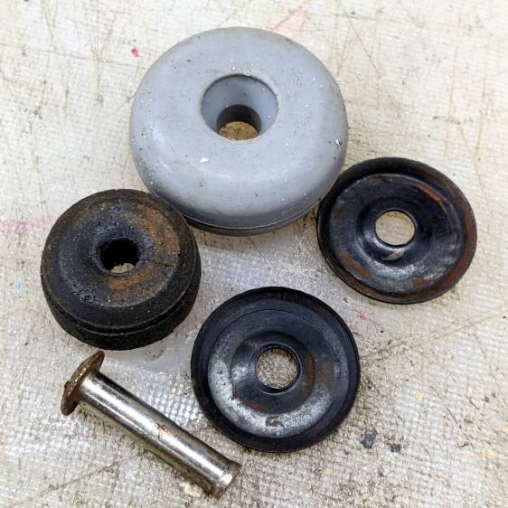
Contrary to what you might think, those rivets never had a head on this side and the bumper seems to be held in place by an interference fit with the plastic handle cover.
A bit of cutoff wheel work removed the crimped end on the 5 mm stud holding the bumper to the pot-metal dingus:
Bypass Lopper – shaft cut
Whacking it with a punch separated all the parts:
Bypass Lopper – bumper parts
The gray thing is a silicone rubber vibration isolator that’s a bit too large in all dimensions, but surely Close Enough™ for present purposes.
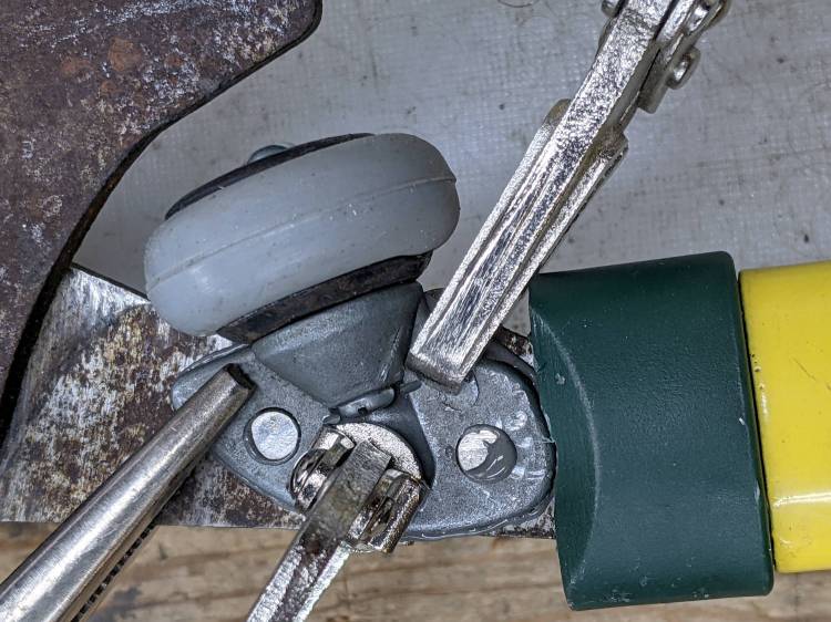
A length of 5 mm shaft became the new stud, with M3×0.5 threads tapped into both ends and a pair of random screws held in place with red Loctite:
Bypass Lopper – epoxy curing
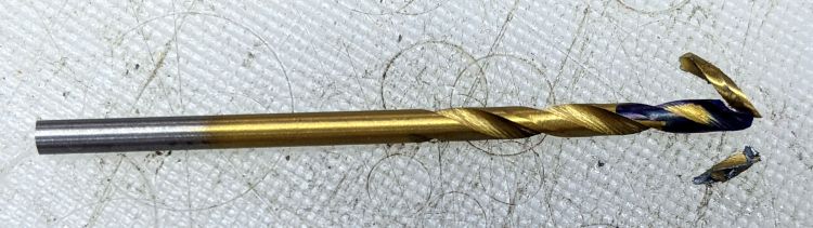
There are no pix of the drilling and threading, as it was accomplished after a shiny-new 2.7 mm “titanium” metric drill from a not-dirt-cheap set shattered in the shaft:
Shattered metric drill
The blue color on the flutes is Sharpie to remind me it’s defunct. I completed the mission using a #36 drill with no further excitement.
The dingus is now held to the lopper with JB Weld and, should that fail, I’ll drill-n-tap the rivets and be done with it.
In the unlikely event I ever give another in-person presentation about 3D printing and what it’s good for, I’ll have some interesting show-n-tell samples. Might have to soak the dirt off, though.