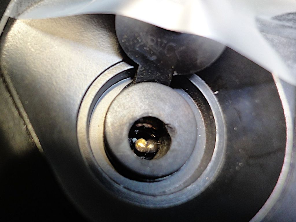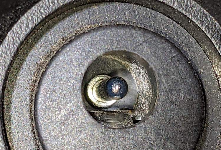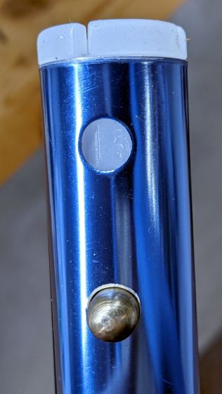
Continuing to mull the problem of removing a brass nugget fused to the center pin of the Bafang battery’s charge port without the risk of causing further damage suggested a shell drill fitting over the pin and guided by an insulating bushing:
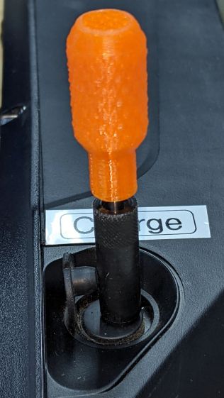
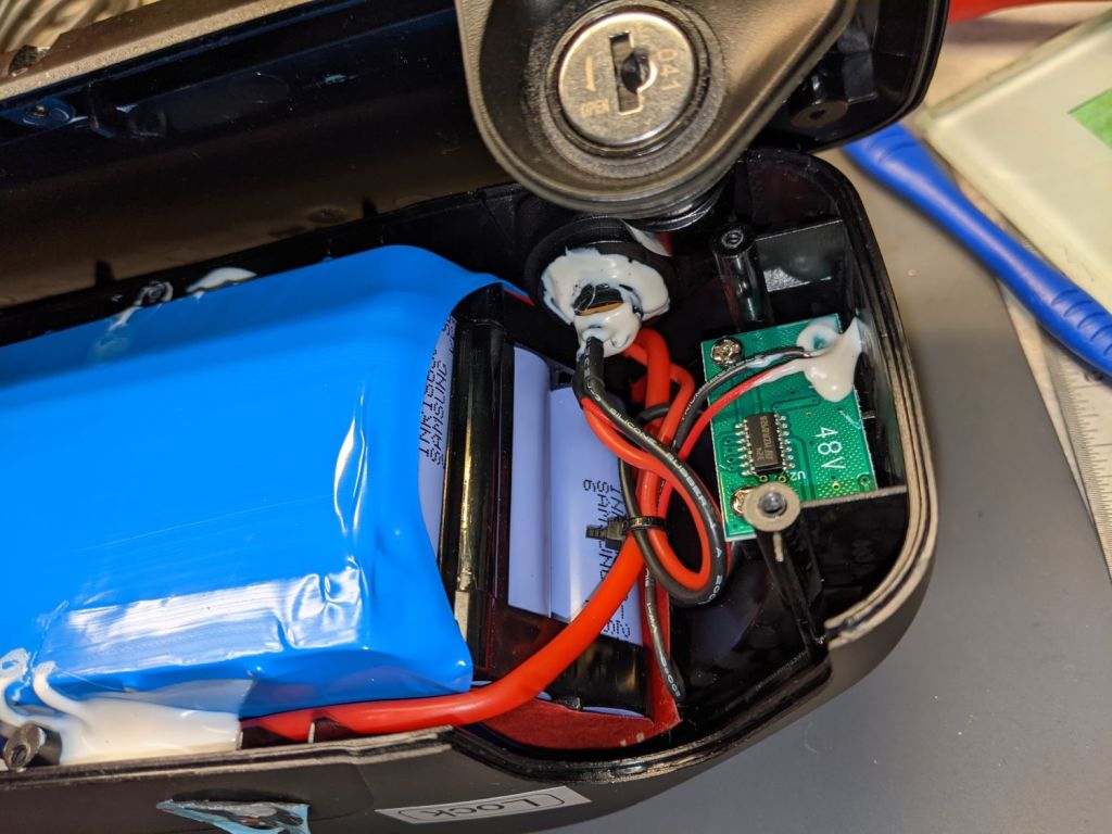
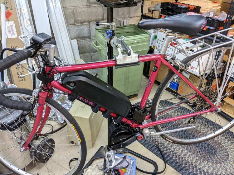
That’s our undamaged battery, now sporting labels inspired by my friend’s mishap.
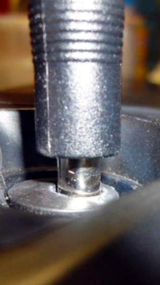
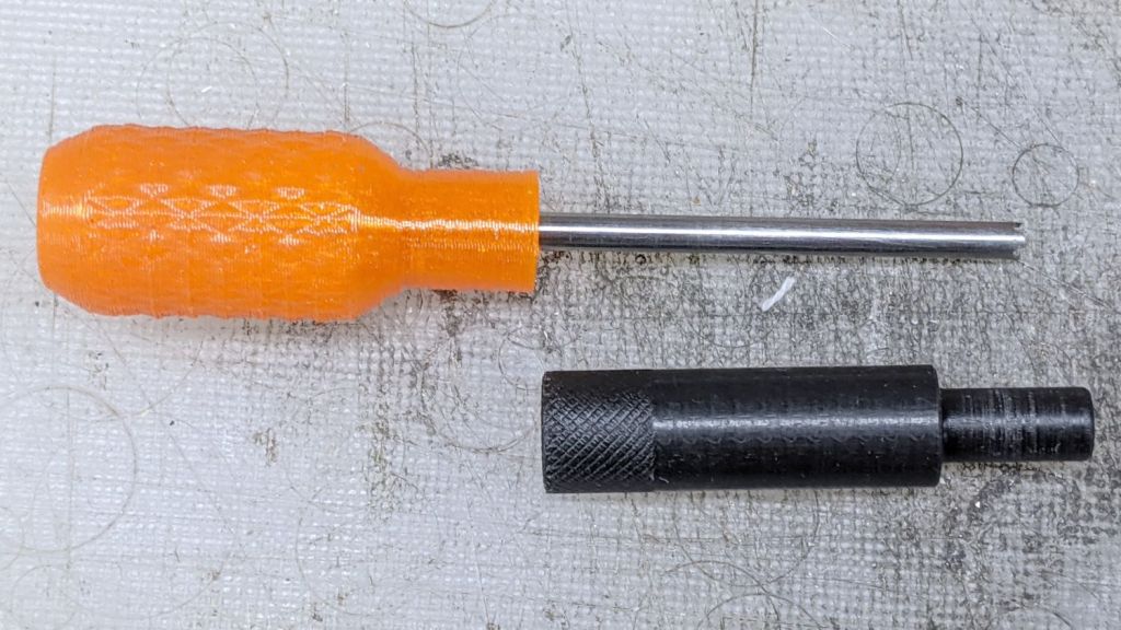
The first pass was a 3 mm (actually, 1/8 inch) brass tube rammed into a printed handle descending from the Sherline Tommy Bar handles:
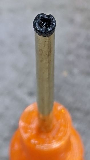
The black stuff is coarse grinding compound held on by a dot of oil, with a pair of notches filed into the tip for a little griptivity.
This worked surprisingly well, at least if you weren’t in much of a hurry, although the grinding compound also erodes the drill:
I hadn’t thought this through enough to realize there’s no good way to convince the grit to not work its way up into the acetal bushing and jam the rod. While this might be good for final polishing, it’s not going to work well against the nugget, so it’s time for a harder drill with real teeth.
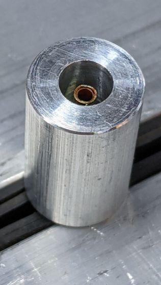
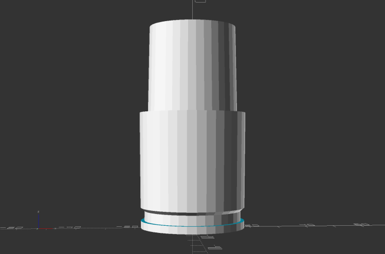
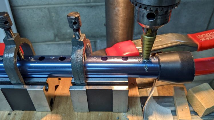
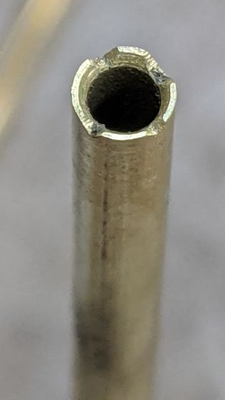
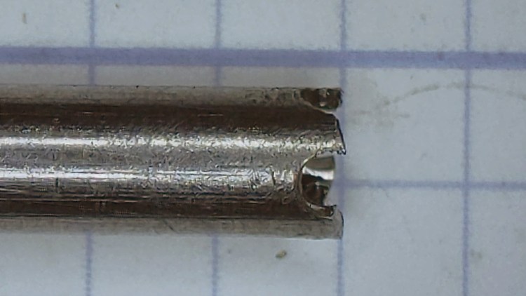
Drilling a 2.3 mm hole into the end of some non-hardened 3 mm (for real!) ground rod provided enough clearance for the charge port pin and a pair of cross-drilled holes laid the groundwork for a shell drill:
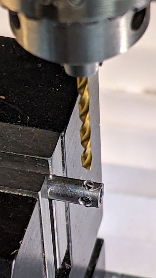
I filed the end off down to leave about 3/4 of the holes, then applied a Swiss pattern file with a safe edge to cut some relief behind the tips:
It would be better to harden the end of the rod, but this is a single-use tool.
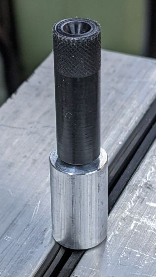
Ram the shank into another printed handle:

The new drill is long enough to reach past the wounded end of the pin and short enough to not bottom out inside the connector.
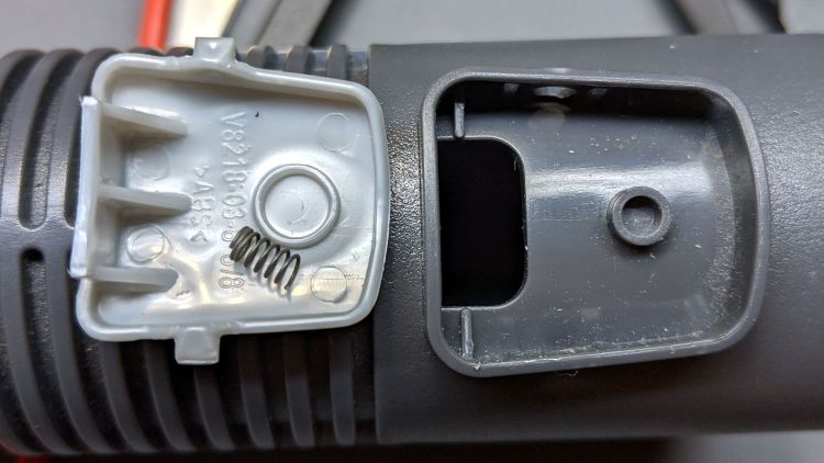
A few minutes of twirling and re-filing the tiny teeth improved the cut enough to produce a convincing result in the simulated connector:
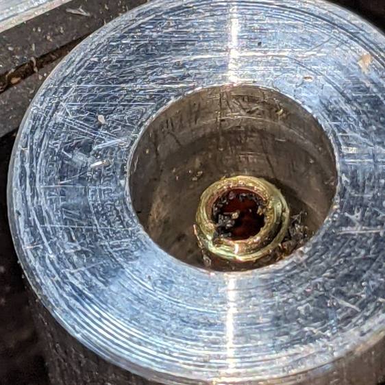
I’m reasonably sure the ID of the acetal bushing won’t fit over the nugget, but that’s easy enough to drill out while leaving an insulating shell.
The charge port’s center pin probably can’t withstand too much torque, so the drill must take small cuts.
Vacuuming out the chips while cutting will be critical, as you don’t want an accumulation of conductive chaff down in the hole!