The Smell of Molten Projects in the Morning

Ed Nisley's Blog: Shop notes, electronics, firmware, machinery, 3D printing, laser cuttery, and curiosities. Contents: 100% human thinking, 0% AI slop.

Category: Home Ec

Things around the home & hearth

  • Juki JC-001 Foot Control: Resolving Uncommanded Thread Cutting

    Juki JC-001 Foot Control: Resolving Uncommanded Thread Cutting

    Mary’s most recent quilt arranges her color choices in Judy Niemeyer’s Stellar Snowflake pattern:

    Stellar Snowflake Quilt - in progress
    Stellar Snowflake Quilt – in progress

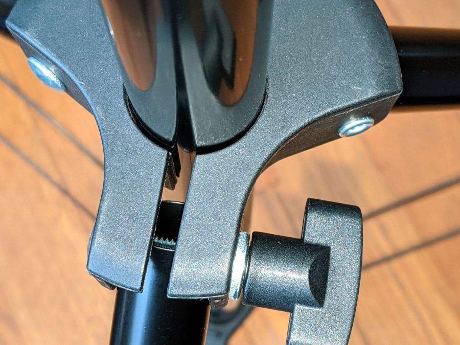
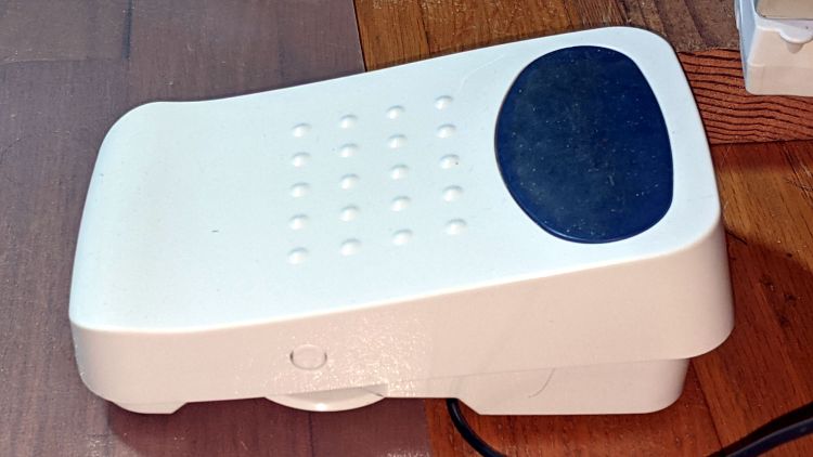
    Her Juki TL-2010Q sewing machine has a built-in thread cutter activated by pressing down on the heel end (to the left) of the foot control:

    Juki JC-001 Foot Control - overview
    Juki JC-001 Foot Control – overview

    The machine had previously performed “uncommanded” thread cuts on other projects, but the many short segments in this pattern triggered far too many cuts. I aimed a camera at her foot on the pedal and she was definitely not pressing down with her heel when the cutter fired.

    In point of fact, the thread cutter fired when she was just starting a new segment, where she was gently pressing down on the toe end (to the right) of the pedal to start at the slowest possible speed.

    For completeness, the underside of the pedal:

    Juki JC-001 Foot Control - bottom
    Juki JC-001 Foot Control – bottom

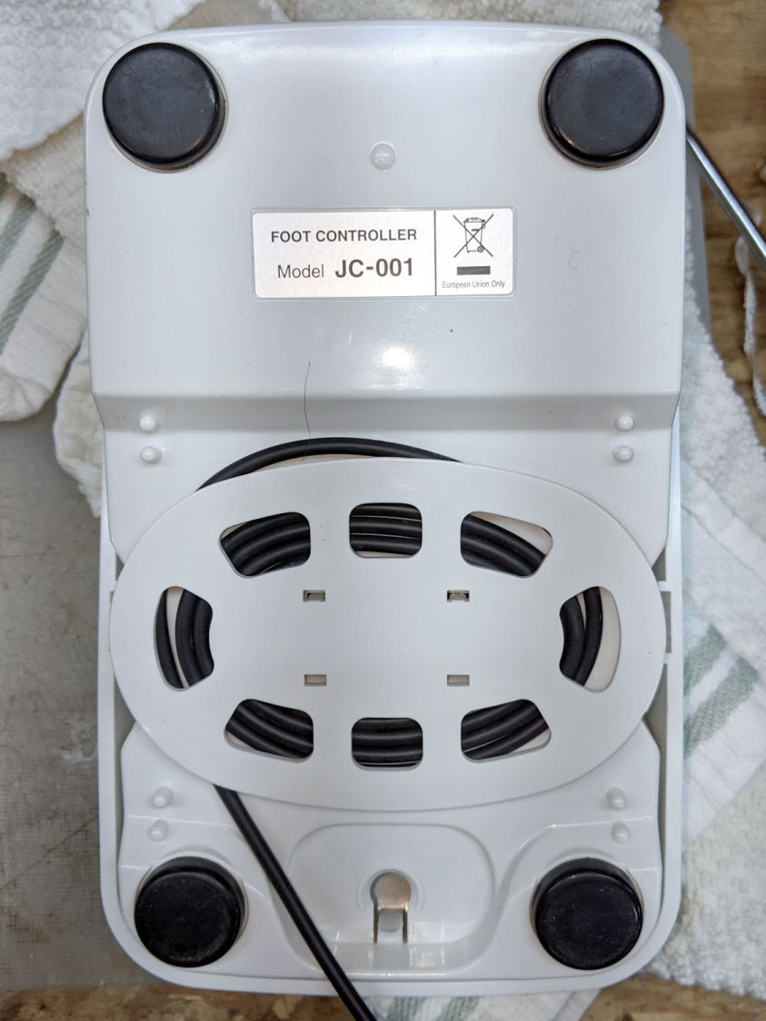
    There are no screws holding it together. The top cover pivots on a pair of plastic pegs sticking out from the base near the middle of the cable spool. Disassembly requires jamming a pair of husky Prydrivers in there and applying enough brute force to pry both sides outward farther than you (well, I) think they should bend. This will scar the bottom of the case, but nobody will ever notice.

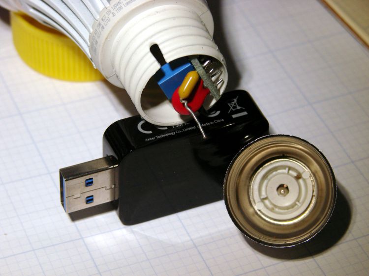
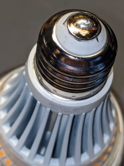
    The foot control cable plugs into the machine through what looks like an ordinary two-conductor coax plug, just like the ones on wall warts delivering power to gadgets around the house. In this day and age, the communications protocol could be anything from a simple resistor to a full-frontal 1-Wire encrypted data exchange.

    Based on the old Kenmore foot pedals, I expected a resistive control and, indeed, a simple test gave these results:

    • Idle = 140 kΩ
    • Heel pressed (cut) = 46 kΩ
    • Toe slight press (slow running) = 20 kΩ
    • Toe full press (fast running) = 0.2 kΩ

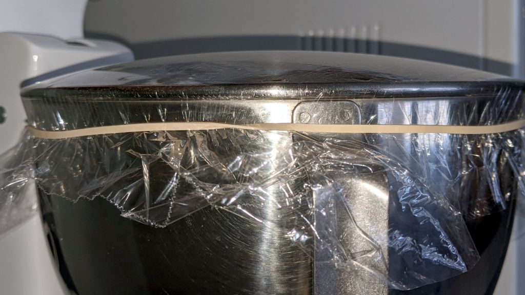
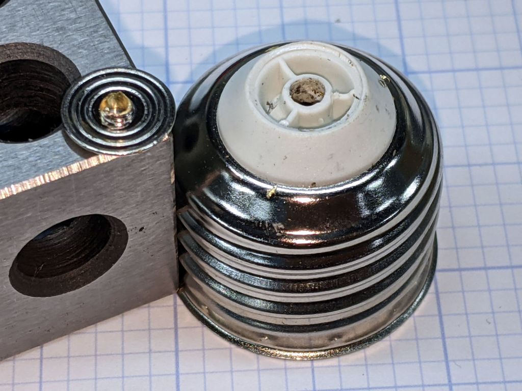
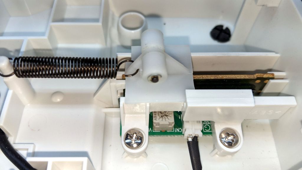
    We can all see where this is going, but just to be sure I pried the top off the control to reveal the insides:

    Juki JJC-001 Foot Control - interior
    Juki JJC-001 Foot Control – interior

    The two cylindrical features capture the ends of a pair of stiff compression springs pressing the top of the pedal upward.

    The small, slightly stretched, extension spring in the middle pulls the slider to the left (heelward), with a ramp in the top cover forcing it to the right (toeward) as the speed increases.

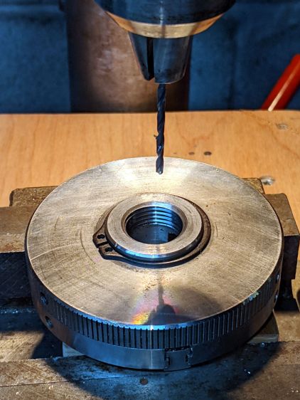
    The top cover includes a surprisingly large hunk of metal which may provide enough mass to make the pedal feel good:

    Juki JC-001 Foot Control - top underside
    Juki JC-001 Foot Control – top underside

    The ramp is plastic and the slider has a pair of nylon (-ish) rollers, so there’s not much friction involved in the speed control part of motion. Yes, this is oriented the other way, with the heel end over on the right.

    The metal insert pivots in the serrated plastic section near the middle, with the two husky extension springs visible on the left holding it against the plastic cover. The two rectangular features on the left rest under the plastic flanges on the right of the base to prevent the metal insert from moving upward, so pressing the heel end down pulls the cover away from the insert to let the slider rollers move toward the right end of the ramp, into roughly the position shown in the interior view.

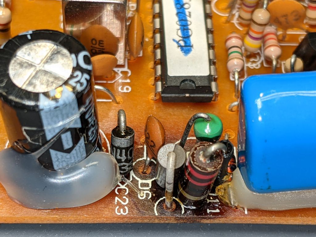
    A closeup look at the slider shows the rollers and the PCB holding all of the active ingredients:

    Juki JC-001 Foot Control - Resistor Slider
    Juki JC-001 Foot Control – Resistor Slider

    I think the trimpot adjusts the starting resistance for the slider’s speed control travel. It is, comfortingly, roughly in the middle of its range.

    A top view shows the fixed 140 kΩ resistor (brown yellow black orange, reading from the right) setting the idle resistance:

    Juki JC-001 Foot Control - PCB top view
    Juki JC-001 Foot Control – PCB top view

    Measuring the resistance while gently teasing the slider showed that it’s possible to produce a resistance higher than 20 kΩ and lower than 140 kΩ, although it requires an exceedingly finicky touch and is completely unstable.

    Before looking inside the pedal, we thought the cutter was triggered by an actual switch closure with the heel end most of the way downward against those stiff springs, which meant the failure came from a switch glitch. Now, we think the earlier and infrequent uncommanded thread cuts trained Mary to start very carefully to be very sure she wasn’t glitching the cutter’s hypothetical switch. Of course, her gradually increasing toe pressure moved the slider very slowly through its idle-to-running transition: she was optimizing her behavior to produce exactly the resistance required to trigger the cutter.

    She now sets the machine’s speed control midway between Turtle and Hare to limit its top speed, presses the pedal with more confidence to minimize the time spent passing through the danger zone, and has had far few uncommanded thread cuts. We think it’s now a matter of retraining her foot to stomp with conviction; there’s no hardware or software fix.

    I’m sure Juki had a good reason to select the resistances they did, but I would have gone for a non-zero minimum resistance at the fast end of travel and a zero-resistance switch to trigger the cutter.

  • Ed’s Low-Effort High Traction Bread

    Ed’s Low-Effort High Traction Bread

    Being that type of guy, perhaps I snug the plastic film over the top of the mixing bowl a bit too securely:

    Yeast at work
    Yeast at work

    The dough descends from my High-Traction Bread, prepared with my low-effort version of the NY Times no-knead recipe.

    The current dramatis personae:

    • 2 cups whole wheat flour (coarse grind OK)
    • 1 cup bread flour
    • ½ cup rye flour
    • ½ cup whey protein (dry milk powder OK)
    • 1 tsp yeast
    • 1 tsp salt
    • 1-½ cup warmish water

    Let the mixer work on the dry ingredients for a while, then slowly pour the water into the bowl. The dough will (probably) become a thick batter, which is perfectly OK. Cover with plastic wrap as above, let it sit from afternoon until the next morning, plop the dough / batter on a floured silicone sheet, chivvy it into a lump, cover with the wrap, let it sit for a couple more hours.

    Fire the oven to 450 °F, get the pot crazy hot, plop the lump inside, cook 25 minutes covered and 10 more uncovered, dump on a rack, slice off a QC sample, slather with butter, enjoy.

    Makes a 700 gram = 24 ounce loaf lump: 1600 kcal, 320 g carb, 90 g protein. A serving might be a scant two ounces: 135 kcal, 26 g carb, 7 g protein.

    Not keto-oid, but it’ll keep you warm in the Basement Laboratory.

    You may safely ignore all recommendations concerning exact times, temperatures, and suchlike; this ain’t no damn fainting-flower souffle.

    You could get used to it …

  • X10 RR501 Transceiver: Heat Death

    X10 RR501 Transceiver: Heat Death

    Must be something in the air:

    X10 RR501 Transceiver - overheated Zener
    X10 RR501 Transceiver – overheated Zener

    Another overheated Zener in another shunt power supply!

    This BZY97C is still a diode, although I didn’t test its 68 V breakdown spec. I have no idea what they’re doing with that much juice inside an X10 RF box and have nowhere near enough interest to find out.

    It still doesn’t work after a Laying On of Hands: out it goes.

  • Fuvaly Bucked Lithium AA Cells

    Behold lithium battery technology, a USB charger, and a buck voltage converter mashed into an AA alkaline package:

    Fuvaly Bucked Lithium AA - label
    Fuvaly Bucked Lithium AA – label

    Those are two of a quartet bought from a randomly named Amazon seller to appease my ancient venerable classic Sony DSC-H5’s need for more voltage than new and freshly charged NiMH AA cells can provide for more than a few tens of minutes.

    The label claims 1500 mA·h, not the 1120 mA·h I measured:

    Fuvaly Bucked Li AA - mAh - 2021-02
    Fuvaly Bucked Li AA – mAh – 2021-02

    My numbers would be higher with a load less than 500 mA. I doubt the 2.5 A maximum current rating.

    The claim of 2.25 W·h is rather optimistic:

    Fuvaly Bucked Li AA - 2021-02
    Fuvaly Bucked Li AA – 2021-02

    Back of the envelope: 2.25 W·h at 1.5 V equals 1.5 A·h, all right. If you squint carefully, though, the output voltages run around 1.4 V, some of which is surely IR drop in my battery holder & test wiring, but it still knocks nearly 10% off the wattage and doesn’t seem to add to the runtime.

    The camera’s battery charge indicator will obviously show Full right up until it shuts off, but I’ve always carried a spare pair of cells in my pocket anyway.

    Recharging them with a USB meter in series required 425 to 600 mA·h at about 4.8 V, so about 2.5 W·h.

    Enlarging the instructions from the back of the box, should they become useful:

    Fuvaly Bucked Lithium AA - Instructions
    Fuvaly Bucked Lithium AA – Instructions

    Nowhere does the package mention the “brand name”, manufacturer, specifications, or much of anything substantial. I suppose anybody selling white-label products appreciates this level of detail.

  • LED Bulb: Mechanical FAIL

    LED Bulb: Mechanical FAIL

    Replacing the second torchiere lamp shade required unscrewing its 100 W equivalent LED bulb, which required far too many turns and eventually felt sufficiently wrong to reveal the problem:

    LED Bulb - unscrewed base
    LED Bulb – unscrewed base

    The entire metal base shell unscrewed from the plastic housing and twisted off the lead from what looks like a PTC fuse in series with the center contact; the cute little pigtail effect suggests I’ve wrecked the epoxy-to-wire seal.

    It had a five year warranty which, alas, expired three years ago. This style of bulb has fallen out of favor, so I may as well get some Quality Shop Time out of it.

    I don’t know how the factory machinery attached the lead to the contact button, but I’m going to go primal on it with some solder. The trick will be soldering it after assembly, so the first step is to drill through the middle of the button.

    Grab it nose-down in the Sherline’s three-jaw chuck, flip it over, grab the chuck in the drill press vise, line it up, center-drill the button, then drill right through that sucker:

    LED Bulb - base drilling setup
    LED Bulb – base drilling setup

    Of course, the contact came loose from the base, because I pretty much drilled right through the rivet flange holding it in place:

    LED Bulb - removed center contact
    LED Bulb – removed center contact

    Nothing a dab of epoxy can’t fix, though. I scuffed up the outside of the contact to remove the nickel (?) plating and expose the underlying brass to improve its solderability.

    After the epoxy cured, align wire with hole, screw the base onto the lamp shell, and it’s ready for soldering:

    LED Bulb - base ready for solder
    LED Bulb – base ready for solder

    The hole is way too large for the wire, but I wasn’t about to wreck a tiny drill on what might have been a weld nugget. In any event, the bigger the blob, the better the job:

    LED Bulb - soldered base
    LED Bulb – soldered base

    Just like light bulb bases used to look, back in the day.

    With a bit of luck, it’ll sit in that socket for another seven years.

    It could happen, ya never know.

  • Torchiere Lamp Shade 2

    Torchiere Lamp Shade 2

    Three and a half years later, the shade on the living room’s other torchiere lamp crumbled at a touch:

    Torchiere Lamp Shade 2 - crumbled
    Torchiere Lamp Shade 2 – crumbled

    Because I live in the future and had solved this problem in the past, eight hours of print time produced a second shade:

    Torchiere Lamp Shade 2 - on platform
    Torchiere Lamp Shade 2 – on platform

    I sliced the same STL file with PrusaSlicer to get G-Code incorporating whatever configuration changes I’ve made to the M2 over the years and include any slicing algorithm improvements; the OpenSCAD code remains unchanged.

    The as-printed shade had pretty much the same crystalline aspect as the first one:

    Torchiere Lamp Shade 2 - no epoxy
    Torchiere Lamp Shade 2 – no epoxy

    Smoothing a layer of white-tinted epoxy over the interior while spinning it slowly in the mini-lathe calmed it down enough for our simple needs, although the picture I tried to take didn’t show much difference.

    That was easy …

  • Photo Backdrop: Wingnut Upgrade

    Photo Backdrop: Wingnut Upgrade

    You’re supposed to secure the photo backdrop’s top crossbar to the uprights by fiddling with a wingnut, which you must do while reaching over your head. Emart apparently realized this operation was fraught with peril, because the package contains four wingnuts. After setting it up once, I replaced the wingnuts with finger-friendly knobs containing acorn nuts:

    Photo Backdrop - thumbscrew vs printed knob
    Photo Backdrop – thumbscrew vs printed knob

    The upright pole ends in an M10×1.5 stud, which fits the biggest acorn nuts in the Warehouse Wing.

    The knobs come from Thingiverse, although the OpenSCAD program required a bit of rework to make it compatible with the current version. Fiddling around with the Customizer parameters produced a Good Enough knob:

    M10x1.5 Acorn Nut knob - solid model
    M10x1.5 Acorn Nut knob – solid model

    I pulled the acorn nut into the knob using the upright pole hardware to keep it aligned. Spin the wingnut on the stud “backwards”, add the washer, push the nut slightly into the knob to get it started, then thread it onto the stud:

    Photo Backdrop - knob nut seating - 1
    Photo Backdrop – knob nut seating – 1

    Turn the knob to pull the nut inward until the stud hits the inside of the nut:

    Photo Backdrop - knob nut seating - 2
    Photo Backdrop – knob nut seating – 2

    Unthread the nut a bit, run the wingnut out to meet the bottom of the knob, and repeat the operation until the nut bottoms out inside the knob:

    Photo Backdrop - knob nut seated
    Photo Backdrop – knob nut seated

    Toss the wingnuts into the Warehouse Wing against later use.

    Bonus project: on the other end of the upright, you’ll find it impossible to actually lock the leg carrier against the pole:

    Photo Backdrop - tripod leg lock
    Photo Backdrop – tripod leg lock

    The plastic fitting is … generously … sized around the 25 mm OD upright pole and requires more compression than I could produce with my puny fingers. It turns out the 18 mm OD leg tube exactly fills the space available inside the fitting, so you (well, I) must squash the steel tube in order to close the fitting on the pole.

    Remove the wingnut + screw to free the end of the leg, stick an inch of the leg into the bench vise’s soft jaws, and mash gently to about 16 mm across the holes; it’ll expand slightly in the other direction. Reassemble in reverse order and discover the thumbscrew now squeezes the fitting exactly as it should.

    There might be more finishing to do when we actually hang a quilt from the stand, but at least it’s now usable.

    Sheesh and similar remarks.