We recently installed a Dripworks drip irrigation system for Mary’s garden and, of course, pre-assembled the emitter / dripline tubing, fittings, and supply / filter / plumbing for each of the beds in the Basement Shop. A few days after burying the main lines, plumbing the filter + pressure regulator, and plugging in half a dozen bed assemblies, Mary noticed some emitter tubes weren’t delivering any water and other beds seemed too dry.
N.B.: We bought everything directly from Dripworks. This is not counterfeit crap from a sketchy Amazon seller.
I cut the dripline just downstream of the Micro-Flow valve on a completely dry bed, whereupon no water emerged. Cutting the supply tube just upstream of the valve produced a jet squirting halfway along the bed. I tried and failed to blow air through the valve: it was completely blocked despite being in the “open” position. I installed another valve and the emitter tube started working properly.
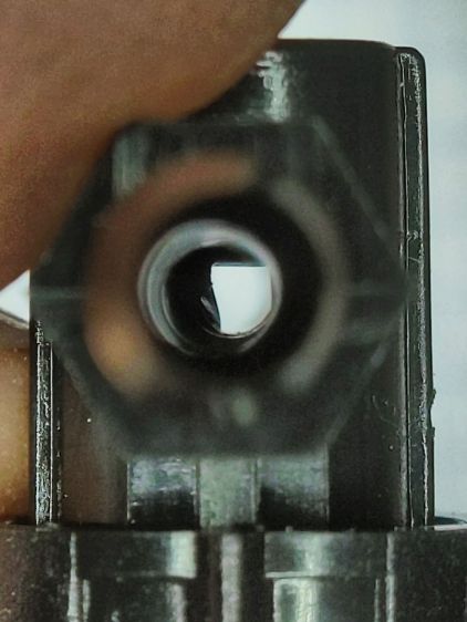
I sat down at the kitchen table with a bag of unused valves and peered through them (the pix are through the microscope):

That’s one of the better-looking valves, with only a little mold flash in the lumen.
Partially occluded lumens were more typical:
Quite a few were almost completely obstructed:

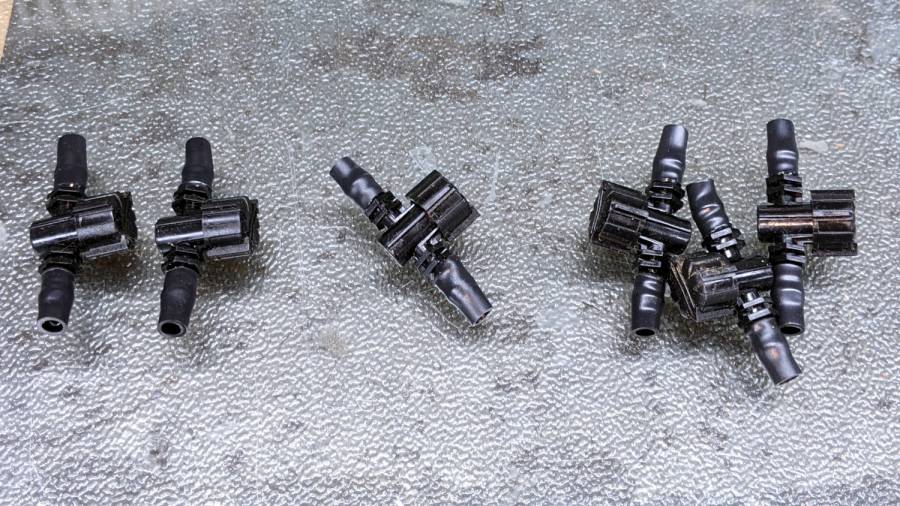
For lack of better instrumentation, I blew through the valves and sorted them by effort:

Two of the valves in the group on the left are completely blocked, with the others mostly blocked.
The middle group has enough mold flash to produce noticeable resistance to the air flow. I think water would have more trouble getting through, but the emitters would at least look like they’re delivering water.
The group on the right has mostly unblocked valves, with visible mold flash but little restriction.
I have no way to measure the actual water flow, so it’s entirely possible the QC spec allows considerable blockage while still delivering enough water to the emitters. More likely, the spec assumes a clear lumen and the mold flash is a total QC faceplant; it’s obviously not a controlled quantity.
Well, I can fix that:

That’s a 2.3 mm drill going straight through the valve body. I drilled the valves from both ends and blew out the swarf:

That produced twenty valves with clear lumens. Of course, the drill leaves a slightly rough interior surface, but it’s now much easier to blow air through them.
We hadn’t installed the driplines in two beds with three emitter tubes per bed. I cut out those six unused valves and sorted them by resistance:
Both of the valves on the left are blocked, the three on the right are mostly OK, and the one in the middle is partially blocked.
With two dozen repaired valves in hand, we returned to the garden, I cut 22 valves out of the installed driplines and replaced them under field conditions. Returning to the Basement Laboratory, I blew the water out (*), sorted them by resistance, and produced a similar distribution, albeit with no pictorial evidence. Although we have no immediate need for the used valves, they’re drilled out and ready for use.
In very round numbers, you should expect:
- A third of Dripworks valves will pass (close to) the expected flow
- A third will have a minor flow restriction
- A quarter will have a severe flow restriction
- One valve in ten will be completely blocked
Plan to drill out all the Micro-Flow valves before you assemble your driplines.
AFAICT, none of the other ¼ inch fittings we used have any interior flash, so it’s only a problem with the valves.
We are, as the saying goes, not amused.
(*) If you will eat a peck of dirt before you die, I’m well on my way.