The Smell of Molten Projects in the Morning

Ed Nisley's Blog: Shop notes, electronics, firmware, machinery, 3D printing, laser cuttery, and curiosities. Contents: 100% human thinking, 0% AI slop.

Category: Home Ec

Things around the home & hearth

  • Whirlpool Refrigerator Drawer Strut Tab Replacement

    The tab supporting the strut with the center slides for the lower drawers in our Whirlpool refrigerator broke of its own accord. This is a problem of long standing, somewhat exacerbated by the fact that lifting the strut will break the tab without much effort at all, but this time the drawers pulled the strut downward hard enough to not only break the tab, but also tear the small tabs that align the bracket right out of the frame.

    While pondering the problem, I glued the broken chunk back into the frame:

    Refrigerator Drawer Strut - clamping front plate
    Refrigerator Drawer Strut – clamping front plate

    We agreed that, after nigh onto two decades, it would be OK to swap the position of the two drawers, so as to let the strut use the undamaged part of the frame seen below. Presumably, we’ll eventually get used to having the apples on the right and the veggies on the left.

    But it was obvious Something Serious Had To Be Done about the tab.

    The tab should align like this inside the frame:

    Refrigerator Drawer Strut Tab - alignment
    Refrigerator Drawer Strut Tab – alignment

    The rightmost part of the tab rests atop a U-shaped metal bar that also supports and stiffens the entire front of the frame, but cantilevering the weight of both drawers on that extended tab overpowered my last attempt at making a glue joint. Soooo, I decided to build a (wait for it …) 3D printed part that screws firmly to the front of the strut.

    The first step involved introducing the strut to Mr Belt Sander to strip the wreckage of the OEM tab from the front end (visible through the opening) and smooth things out, then measuring the remainder. The locating flange inside the frame almost defeated me, but eventually I found a tool that fit inside the strut opening and around the flange:

    Refrigerator Drawer - measuring flange
    Refrigerator Drawer – measuring flange

    Which produced a sketch of the key dimensions:

    Refrigerator Drawer Strut - Dimension Doodles
    Refrigerator Drawer Strut – Dimension Doodles

    Which became an extruded polygon with a few holes punched in the side:

    Refrigerator Shelf Strut Tab - solid model
    Refrigerator Shelf Strut Tab – solid model

    Building it standing up wraps the plastic threads around the entire tab and stacks the layers along the length of the tab. Doing it lying down in the obvious hump-up orientation would put the layers parallel to the bottom surface, where they can pull apart under load.

    The key innovation here involves being willing to assemble the tab to the strut in situ, without insisting it fit through the frame opening and be more-or-less easily removable. That let me bulk up the tab to match the end of the strut, fill the entire frame opening with plastic, and get enough bulk for a pair of 4-40 screws that, being loaded in shear, should withstand the weight of all those fruits & veggies in the drawers.

    The screws simply thread into the holes in the tab, without benefit of tapping. The OpenSCAD code now includes a pair of nut traps, but I’m hoping they won’t be needed.

    The new tab really does fill the space available:

    Refrigerator Drawer Strut - new tab in place
    Refrigerator Drawer Strut – new tab in place

    The OpenSCAD code now moves the notch half a millimeter further away from the strut to center it over the ridge. What’s not obvious is how the frame slants toward the tab over the U-bar: the tab just barely clears and probably should have a tapered nose. You may add that if you like.

    The U-shaped bar constrains the tab pretty firmly and supports the end, which should now be plump enough to withstand the forces involved. The screws sit horizontally with the frame installed and can’t pull out, which is why I think they can get along without nut traps.

    It’s built in cyan PETG with three perimeter threads and 40% 3D Honeycomb fill, making it essentially a solid block of plastic; it’ll be interesting to see what fails next.

    The OpenSCAD source code, which I hammered out in a white-hot fury:

    // Refrigerator Shelf Strut Tab
    // Ed Nisley KE4ZNU December 2015
    
    //- Extrusion parameters must match reality!
    
    ThreadThick = 0.25;
    ThreadWidth = 0.40;
    
    HoleWindage = 0.2;
    
    Protrusion = 0.1;			// make holes end cleanly
    
    inch = 25.4;
    
    function IntegerMultiple(Size,Unit) = Unit * ceil(Size / Unit);
    
    //----------------------
    // Dimensions
    
    TabSize = [20.0,12.0,35.0];							// length from bracket, height, width along front
    
    SlotSize = [3.0,7.0];
    SlotX = 7.0;
    
    TabProfile = [
    	[0,0],
    	[12,0],	[12,7.0],
    	[TabSize[0],7.0], [TabSize[0],TabSize[1]],
    	[SlotX + SlotSize[0]/2,TabSize[1]],
    	[SlotX + SlotSize[0]/2,5.0], [SlotX - SlotSize[0]/2,5.0],
    	[SlotX - SlotSize[0]/2,TabSize[1]],
    	[0,TabSize[1]]
    ];
    
    ScrewY = 7.0;
    ScrewOC = 25.0;
    ScrewOD = 2.5;
    
    NutOD = 6.6;					// across flats
    NutThick = 2.5;
    
    //----------------------
    // Useful routines
    
    module PolyCyl(Dia,Height,ForceSides=0) {			// based on nophead's polyholes
    
      Sides = (ForceSides != 0) ? ForceSides : (ceil(Dia) + 2);
    
      FixDia = Dia / cos(180/Sides);
    
      cylinder(r=(FixDia + HoleWindage)/2,
    		h=Height,
    	$fn=Sides);
    }
    
    //----------------------
    // Build it
    
    difference() {
    	linear_extrude(height=TabSize[2],convexity=4)
    		polygon(points=TabProfile);
    	
    	for (i=[-1,1]) {
    		translate([-Protrusion,ScrewY,i*ScrewOC/2 + TabSize[2]/2])
    			rotate([0,90,0])
    				rotate(180/6)
    					PolyCyl(ScrewOD,SlotX,6);
    		translate([SlotX - SlotSize[0]/2 - NutThick - Protrusion,ScrewY,i*ScrewOC/2 + TabSize[2]/2])
    			rotate([0,90,0])
    				rotate(180/6)
    					PolyCyl(NutOD,NutThick + SlotSize[0],6);
    	}
    }
    

    Maybe that’ll last until we finally scrap out the refrigerator…

  • Would You Pull the Tab?

    So this device showed up in an envelope with a letter telling us we’d won a contest if, of course, the number on the device matched the number in the letter:

    CodeKase device
    CodeKase device

    I wonder if anybody else had second thoughts about pulling what’s obviously an insulating sheet holding two contacts apart? In this day and age, getting the victim to blow his own fingers off probably counts as a win.

    Maybe it comes from having read The White Plague at an impressionable age. Who could resist getting a Nice Thing in the mail?

    The number matched, of course, but the letter’s finer print said the prize would be one of:

    • A new car of some sort
    • A flat screen TV
    • A cheap electronic trinket
    • A three-day / two night vacation

    In order to claim your prize, you had to call an 800 number. The much finer print revealed the odds of winning the first three of those prizes was somewhere around 300,000:1. “Winning” the vacation was essentially a slam-dunk proposition, of course, and probably tells you everything you need to know about the course of the phone call.

    It’s apparently economical to send out this much hardware to reel in new “customers”:

    CodeKase device - parts
    CodeKase device – parts

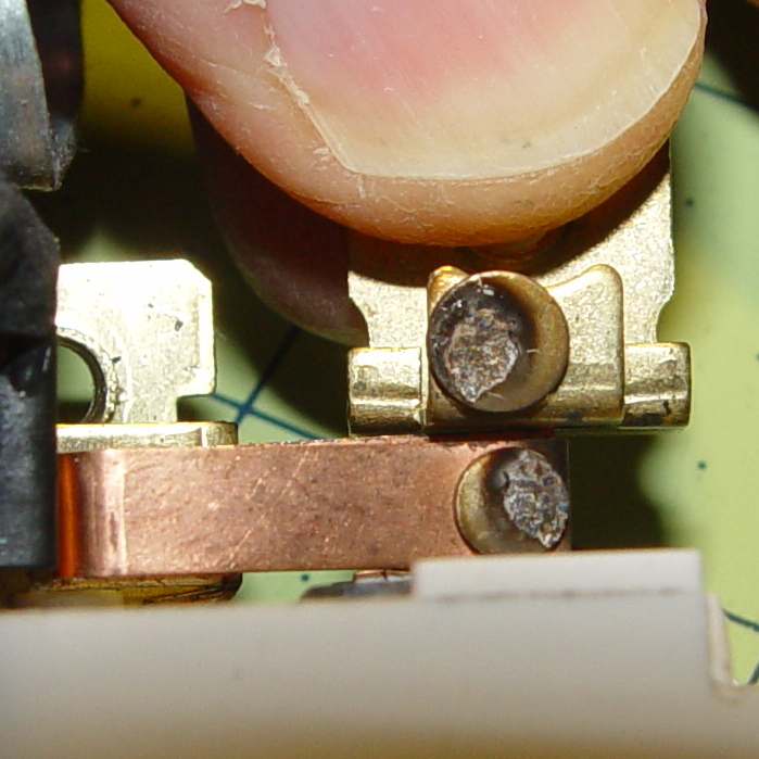
    Using the metal disk from a membrane switch as a spring to push the coin cell against the contact wires is a nice touch. This is apparently the optimized version that uses a single lithium cell in place of two alkaline buttons; the cell “socket” on the other end consists of vestigial lumps.

    I harvested the lithium cell and the blue LED, of course…

    More about CodeKase, direct from the source. I like “Step Five: Recycle Your CodeKase”…

  • Kenmore Vacuum Cleaner Tool Adapters

    After donating the neversufficiently-to-be-damned Samsung vacuum cleaner (and all its remaining bags & doodads) to a nonprofit’s tag sale, we picked up a Sears Kenmore Progressive vacuum cleaner that seemed to be the least awful of the current offerings. Unlike all previous vacuum cleaners, its tools & doodads have complex plastic fittings with latches and keyways and all manner of gimcrackery. The designers seem to have hands and legs of far-above-average size, but that’s another rant.

    All this came to a head when I attempted to vacuum the fuzz out of the refrigerator’s evaporator coils, because the long snout that reaches the back of the refrigerator doesn’t fit the aperture in the giant handle.

    Well, at least I can fix that

    The first step involved modeling the plastic fitting that snaps into the handle:

    Kenmore Male Fitting - Solid model
    Kenmore Male Fitting – Solid model

    The latch on the handle snaps into an opening that took some tinkering to reproduce. Stand back, I’m going to use trigonometry:

                translate([0,-11.5/2,23.0 - 5.0])                                    // latch opening
                    cube(Latch);
                    
                translate([OEMTube[ID1]/2 + EntryHeight/tan(90-EntryAngle),0,0])    // latch ramp
                    translate([(Latch[1]/cos(180/EntrySides))*cos(EntryAngle)/2,0,(Latch[1]/cos(180/EntrySides))*sin(EntryAngle)/2])
                        rotate([0,-EntryAngle,0])
                            intersection() {
                                rotate(180/EntrySides)
                                    PolyCyl(Latch[1],Latch[0],EntrySides);
                                translate([-(2*Latch[0])/2,0,-Protrusion])
                                    cube(2*Latch[0],center=true);
                            }
    

    Which spits out two suitable shapes with the proper positions and alignments:

    Kenmore Male Fitting - Latch detail - Solid model
    Kenmore Male Fitting – Latch detail – Solid model

    The magic wand for the refrigerator originally slid into the Samsung’s metal pipe, so I put a slightly tapered cylinder inside a somewhat more tapered exterior (which seems chunky enough to withstand my flailing around under the refrigerator), then topped it off with the male fitting:

    Refrigerator Coil Wand Adapter
    Refrigerator Coil Wand Adapter

    The Kenmore crevice tool snaps under the gargantuan plastic handle, which limits it to being 6.5 inches long, totally unable to reach into any of the nontrivial crevices around here, and in the way when it’s not being used. Some rummaging turned up a longer crevice tool from the Electrolux That Came With The House™, an old-school tool that slipped over its pipe. Modeling a straight cylinder inside a tapered cylinder that fits the tool didn’t take long:

    Crevice Tool Adapter
    Crevice Tool Adapter

    Flushed with success, I found a smaller floor brush than the new Kenmore, with dimensions similar to the Electrolux snout, so another module appeared:

    Floor Brush Adapter
    Floor Brush Adapter

    All of them build with the latch end upward to avoid needing support structure, with a 5 mm brim for good platform adhesion:

    Floor Brush Adapter - Slic3r preview
    Floor Brush Adapter – Slic3r preview

    I printed them during the PDS Mini Maker Faire as examples of Useful Things You Can Do With a 3D Printer:

    Kenmore Vacuum Cleaner - Tool Adapters
    Kenmore Vacuum Cleaner – Tool Adapters

    As I pointed out to nearly everybody, the Big Lie about 3D printing is that you’ll just download somebody else’s model to solve your problem. In general, that won’t work, because nobody else has your problem; if you can’t do solid modeling, there’s no point in you having a 3D printer. There’s also no point in going to Kinko’s to get a standardized 3D printed doodad, because you can just order a better-looking injection-molded part directly from Sears (or an aftermarket source) and be done with it.

    I loves me some good OpenSCAD action on my Makergear M2, though…

    The OpenSCAD source code:

    // Kenmore vacuum cleaner nozzle adapters
    // Ed Nisley KE4ZNU November 2015
    
    // Layout options
    
    Layout = "CreviceTool";        // MaleFitting CoilWand FloorBrush CreviceTool
    
    //- Extrusion parameters must match reality!
    //  Print with +1 shells and 3 solid layers
    
    ThreadThick = 0.25;
    ThreadWidth = 0.40;
    
    HoleWindage = 0.2;
    
    function IntegerMultiple(Size,Unit) = Unit * ceil(Size / Unit);
    
    Protrusion = 0.1;           // make holes end cleanly
    
    //----------------------
    // Dimensions
    
    ID1 = 0;                                                // for tapered tubes
    ID2 = 1;
    OD1 = 2;
    OD2 = 3;
    LENGTH = 4;
    
    OEMTube = [35.0,35.0,41.7,40.5,30.0];                    // main fitting tube
    EndStop = [OEMTube[ID1],OEMTube[ID2],47.5,47.5,6.5];    // flange at end of main tube
    
    FittingOAL = OEMTube[LENGTH] + EndStop[LENGTH];
    
    $fn = 12*4;
    
    //----------------------
    // Useful routines
    
    module PolyCyl(Dia,Height,ForceSides=0) {           // based on nophead's polyholes
    
    Sides = (ForceSides != 0) ? ForceSides : (ceil(Dia) + 2);
    
    FixDia = Dia / cos(180/Sides);
    
    cylinder(r=(FixDia + HoleWindage)/2,
             h=Height,
             $fn=Sides);
    }
    
    
    //-------------------
    // Male fitting on end of Kenmore tools
    // This slides into the end of the handle or wand and latches firmly in place
    
    module MaleFitting() {
        
    Latch = [40,11.5,5.0];                    // rectangle latch opening
    EntryAngle = 45;                        // latch entry ramp
    EntrySides = 16;
    EntryHeight = 15.0;                        // lower edge on *inside* of fitting
    
    KeyRadius = 1.0;
            
        translate([0,0,6.5])
            difference() {
                union() {
                    cylinder(d1=OEMTube[OD1],d2=OEMTube[OD2],h=OEMTube[LENGTH]);            // main tube
                    
                    hull()                                                                    // insertion guide
                        for (i=[-(6.0/2 - KeyRadius),(6.0/2 - KeyRadius)], 
                            j=[-(28.0/2 - KeyRadius),(28.0/2 - KeyRadius)], 
                            k=[-(26.0/2 - KeyRadius),(26.0/2 - KeyRadius)])
                            translate([(i - (OEMTube[ID1]/2 + OEMTube[OD1]/2)/2 + 6.0/2),j,(k + 26.0/2 - 1.0)])
                                sphere(r=KeyRadius,$fn=8);
                    
                    translate([0,0,-EndStop[LENGTH]])                                // wand tube butts against this
                        cylinder(d=EndStop[OD1],h=EndStop[LENGTH] + Protrusion);
                }
                
                translate([0,0,-OEMTube[LENGTH]])                                    // main bore
                    cylinder(d=OEMTube[ID1],h=2*OEMTube[LENGTH] + 2*Protrusion);
                    
                translate([0,-11.5/2,23.0 - 5.0])                                    // latch opening
                    cube(Latch);
                    
                translate([OEMTube[ID1]/2 + EntryHeight/tan(90-EntryAngle),0,0])    // latch ramp
                    translate([(Latch[1]/cos(180/EntrySides))*cos(EntryAngle)/2,0,(Latch[1]/cos(180/EntrySides))*sin(EntryAngle)/2])
                        rotate([0,-EntryAngle,0])
                            intersection() {
                                rotate(180/EntrySides)
                                    PolyCyl(Latch[1],Latch[0],EntrySides);
                                translate([-(2*Latch[0])/2,0,-Protrusion])
                                    cube(2*Latch[0],center=true);
                            }
            }
    }
    
    //-------------------
    // Refrigerator evaporator coil wand
    
    module CoilWand() {
        
        union() {
            translate([0,0,50.0])
                rotate([180,0,0])
                    difference() {
                        cylinder(d1=EndStop[OD1],d2=42.0,h=50.0);
                        translate([0,0,-Protrusion])
                            cylinder(d1=35.0,d2=35.8,h=100);
                    }
            translate([0,0,50.0 - Protrusion])
                MaleFitting();
        }
    }
    
    
    //-------------------
    // Refrigerator evaporator coil wand
    
    module FloorBrush() {
        
        union() {
            translate([0,0,60.0])
                rotate([180,0,0])
                    difference() {
                        union() {
                            cylinder(d1=EndStop[OD1],d2=32.4,h=10.0);
                            translate([0,0,10.0 - Protrusion])
                                cylinder(d1=32.4,d2=30.7,h=50.0 + Protrusion);
                        }
                        translate([0,0,-Protrusion])
                            cylinder(d1=28.0,d2=24.0,h=100);
                    }
            translate([0,0,60.0 - Protrusion])
                MaleFitting();
        }
    }
    
    
    //-------------------
    // Crevice tool
    
    module CreviceTool() {
        
        union() {
            translate([0,0,60.0])
                rotate([180,0,0])
                    difference() {
                        union() {
                            cylinder(d1=EndStop[OD1],d2=32.0,h=10.0);
                            translate([0,0,10.0 - Protrusion])
                                cylinder(d1=32.0,d2=30.4,h=50.0 + Protrusion);
                        }
                        translate([0,0,-Protrusion])
                            cylinder(d1=28.0,d2=24.0,h=100);
                    }
            translate([0,0,60.0 - Protrusion])
                MaleFitting();
        }
    }


    //----------------------
    // Build it!
    
    if (Layout == "MaleFitting")
        MaleFitting();
    
    if (Layout == "CoilWand")
        CoilWand();
    
    if (Layout == "FloorBrush")
        FloorBrush();
    
    if (Layout == "CreviceTool")
        CreviceTool();
    
    
  • Ed’s Fireball Hot Cocoa Recipe

    The hot chocolate recipe on the back of the cocoa container tastes like bland liquid candy.

    This tastes the way hot cocoa should:

    Ingredients

    • 1 generous cup milk (full-fat is where it’s at)
    • 1 tbsp white sugar (just do it)
    • 3 tbsp cocoa powder (not chocolate drink mix)
    • 1/4 tsp Vietnamese cinnamon
    • 1 tbsp milk for mixing
    • few drops peppermint extract
    • 1/4 tsp vanilla extract
    • 20 oz Starbucks City Mug (got ’em cheap at a tag sale)

    Preparation

    • Microwave the generous cup o’ milk for 1 minute
    • Mix dry ingredients in the giant mug
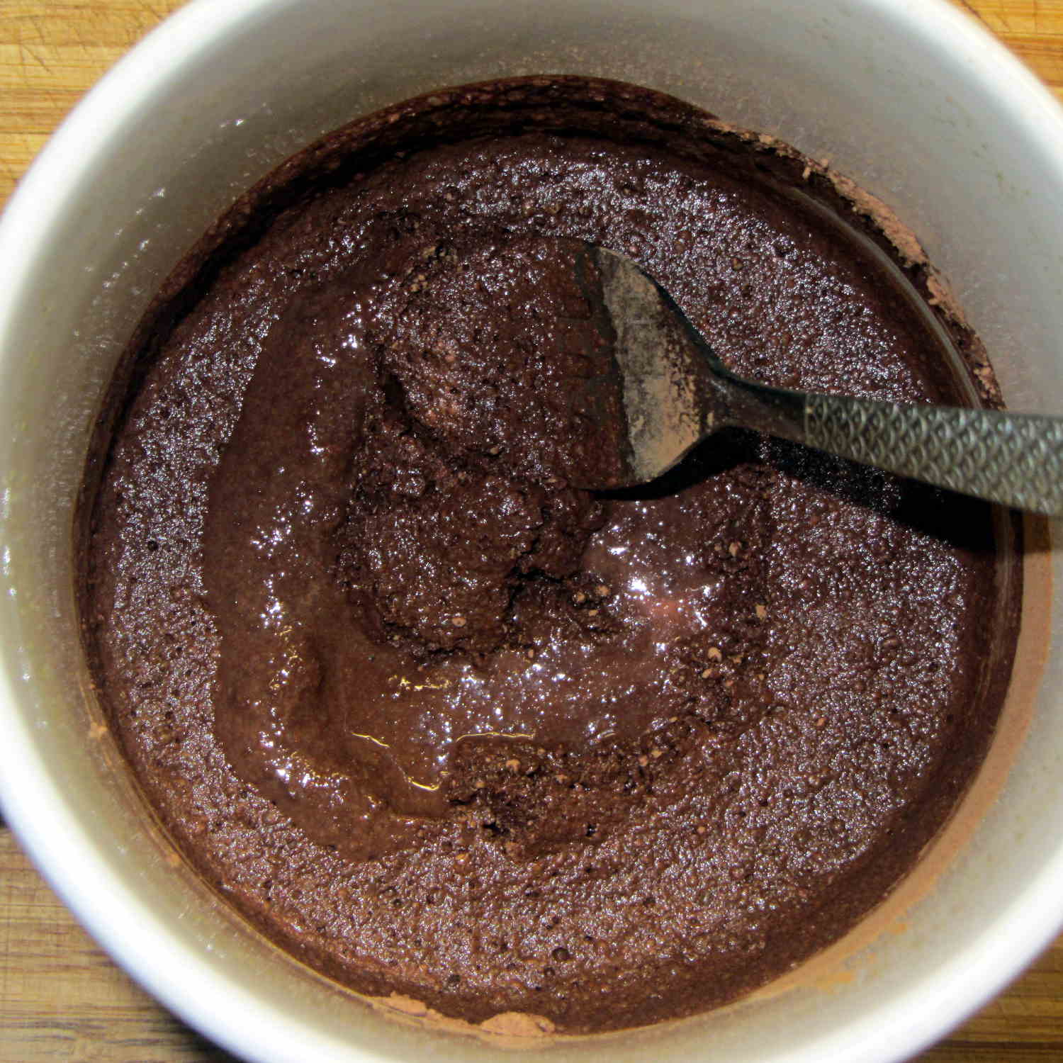
    • Stir in just enough cold milk to make a thick mud (*)
    • Add peppermint drops using 1/4 tsp measure
    • Rinse 1/4 tsp measure with vanilla
    • Blend the extracts into the mud (*)
    • Stir in warm milk, scraping mud off the mug
    • Microwave for another 45 s or so
    • Stir to blend

    What’s going on:

    • More cocoa = more flavor, pure & simple
    • Less sugar = more cocoa bite
    • Vietnamese cinnamon adds the aroma & zip of those old Atomic Fireballs
    • Vanilla smooths the taste
    • Peppermint reminds you it’s winter

    Sipping a cup in the afternoon banishes the urge to power-nosh anything else until suppertime…

    * Update: non-alkalized / non-Dutch-process cocoa doesn’t blend well. Mix up the mud, let it set for 15 minutes, blend again, pause for 5 minutes, then proceed. Wonderfully smooth with no powder bombs.

  • Painting By Numbers

    The south- and snowplow-facing numbers on the mailbox weren’t up to the challenge:

    Mailbox - faded numbers
    Mailbox – faded numbers

    I wiped the crud off the reflective labels with denatured alcohol before painting, but that was the extent of the surface preparation.

    I’m not getting graded on my ability to paint within the lines using a foam brush and that’s a Good Thing:

    Mailbox - repainted numbers
    Mailbox – repainted numbers

    That’s Rustoleum Rusty Metal Primer, chosen entirely because it was oil-based, outdoor-rated, and near the front of the shelf. I’m not going to topcoat it; that stuff is on its own. The slight color variations show still-wet primer here & there.

    The north-facing numbers were in better shape, so a few dabs covered the obvious problems.

    Hey, I wiped that peeling paint off the top of the box, too…

  • Garage Door Torsion Spring Break

    The really good thing about having torsion springs on the garage door is that when one breaks, not much happens:

    Garage door torsion spring - broken end
    Garage door torsion spring – broken end

    We decided to spray money on the problem and make it go away; the Dutchess Overhead Doors tech was here the morning after I called: quicker than Amazon Prime and he works much faster than I can.

    As nearly as I can tell from the checkbook (remember checkbooks?), an original (to us, anyway) spring broke shortly after we moved in. If so, that spring lasted nearly 17 years; at two open-shut cycles per day, let’s call it 12,000 cycles.

    For the record, the springs are:

    • 29 inches long
    • 1-3/4 inch ID
    • 0.250 wire
    • 7 foot tall door

    He cranked in seven full turns, corresponding to the “one turn per foot of door height” rule, although the door doesn’t quite balance on its own. I’d have done one more quarter-turn to match the chalk above the door (a good example of write it where you use it), plus maybe another for good measure, but I’m reluctant to mess with success:

    dsc08582 - Garage door torsion spring - installedPerhaps the 1955 springs were 32 inches long, but the tech replaced what he found both times. It’s a brute of a door, two generous cars wide, with plywood panels in heavy wood framing, plus a few pounds of filler I applied to the rather crazed surface before painting it some years ago.

    I’m mildly surprised none of the dimensions changed in the last 60 years: the springs, end caps, pulleys, and hardware directly interchanged.

  • Sears Sewing Table: Shortened Legs With Levelers

    Mary picked up a sewing table at a tag sale:

    Sears Sewing Table - installed
    Sears Sewing Table – installed

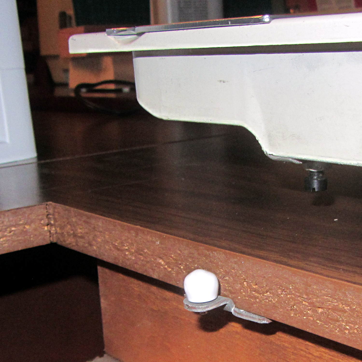
    It has a number of shortcomings (notice the padding taped to the corner of the useless drawers), but the most pressing problem was that it didn’t quite line up with the table top in the Basement Sewing Room. After some pondering, we decided to shorten the legs and install leveling screws.

    The first problem was figuring out how to dismantle the thing. It turns out the legs have completely hidden joint hardware:

    Sears Sewing Table - leg joint hardware
    Sears Sewing Table – leg joint hardware

    They’re obviously intended as assemble-only fittings, but prying from the inside of the corners will put the tool marks where they can’t be seen:

    Sears Sewing Table - leg removal
    Sears Sewing Table – leg removal

    The legs taper below the fittings and require shims to prevent horrible saw accidents:

    Sears Sewing Table - leg shortening
    Sears Sewing Table – leg shortening

    Another in my continuing series of Why You Can Never Have Too Many Clamps shows the square section of the leg aligned with the saw fence:

    Sears Sewing Table - leg clamps
    Sears Sewing Table – leg clamps

    And when the cuttin’ were done, it turned out that the table had two different types of legs with (at least) two different lengths:

    Sears Sewing Table - leg cutoffs
    Sears Sewing Table – leg cutoffs

    I have a bunch of 5/16 inch feet from some random industrial hardware, so I drilled a 5/16 inch hole into the legs, using a doweling jig and more shims:

    Sears Sewing Table - leg drilling setup - overview
    Sears Sewing Table – leg drilling setup – overview

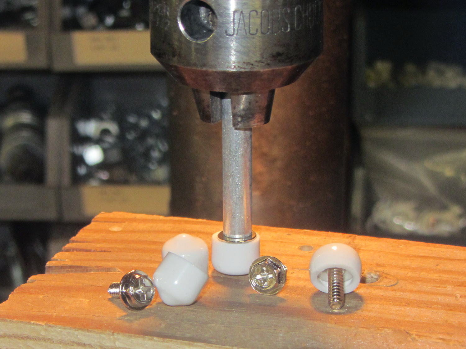
    Normally, you’d bang a T-nut into each leg, but I thought those spikes would split the minimal wood remaining around the hole, so I turned the corners off a quartet of ordinary hex nuts and laid a coarse groove along their length:

    Sears Sewing Table - preparing nut inserts
    Sears Sewing Table – preparing nut inserts

    The modified nuts are 1/2 inch OD and you should drill that hole before the longer 5/16 inch clearance hole. I’ll eventually dab some epoxy in the holes, seat the nuts, and that’ll be a permanent installation with no risk of cracking the legs.

    The snippet of tape on the doweling jig remembers the drill guide position, but the legs were sufficiently different that each one required different shims and some hand-tuning:

    Sears Sewing Table - leg drilling setup - detail
    Sears Sewing Table – leg drilling setup – detail

    I dry-assembled the table in anticipation of more modifications. Basically, you wiggle-jiggle the leg studs into their latches, then whack the end of the leg with a rubber mallet to seat it against the underside of the tabletop.

    Slicing another half inch off the legs seems like a Good Idea that should better match the upstairs table. Mary also wants to round off the drawers and remove a bit of the front panel, which will require dismantling the entire table, but that can wait for a pause in the quilting.