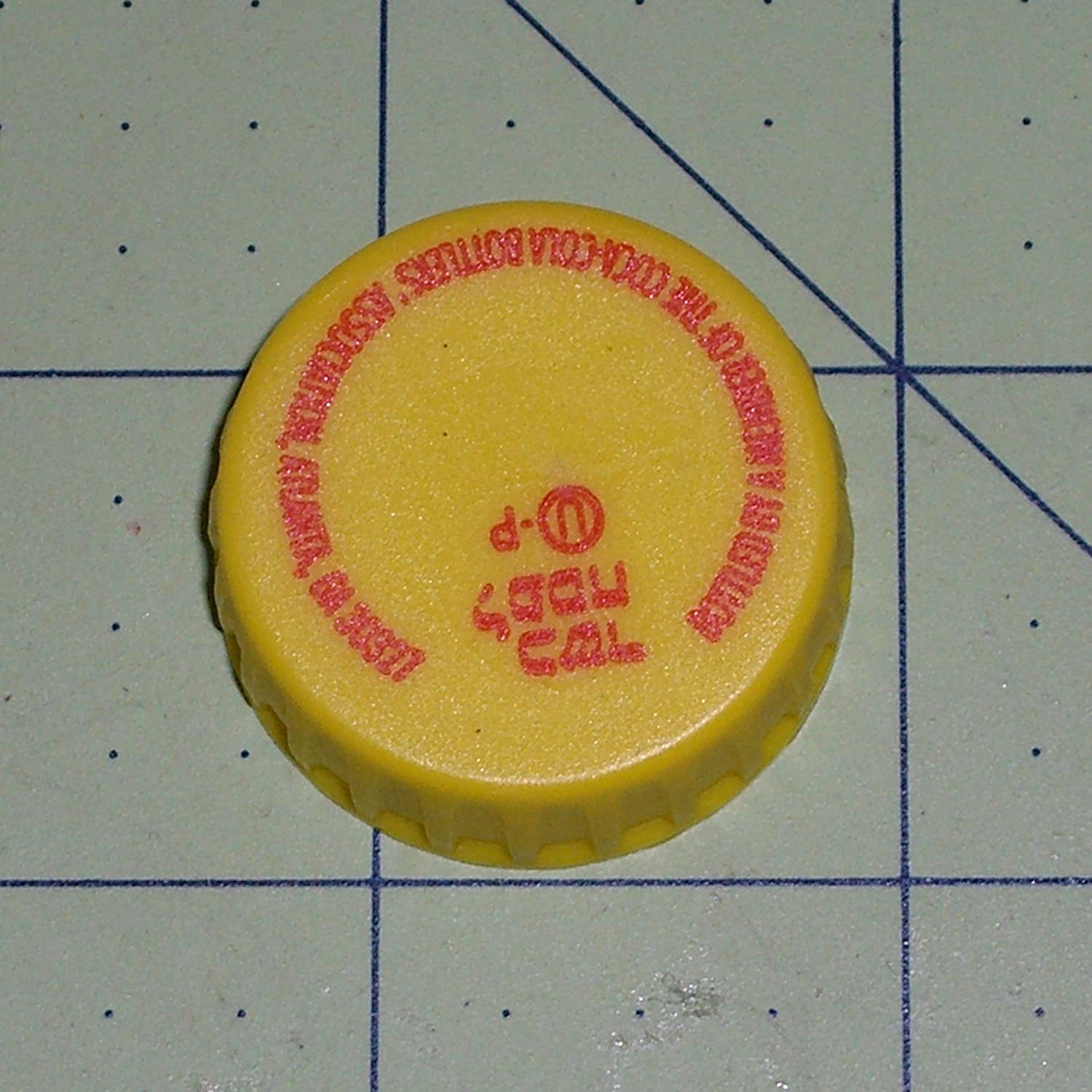
After about 1 TB of data spread over three months and maybe 100 bike rides, the second Sony SR-64UY 64 GB MicroSDXC card I bought last summer has failed… barely two weeks inside the one year warranty.
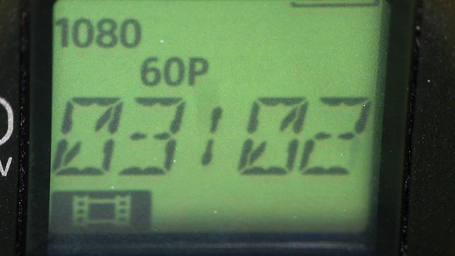
As with the first card, this one works fine except for the speed: it cannot record at 1920x1080p @ 60 fps. The only indication comes from aiming another camera at the display to capture the failure as it happens.
Just before the failure:
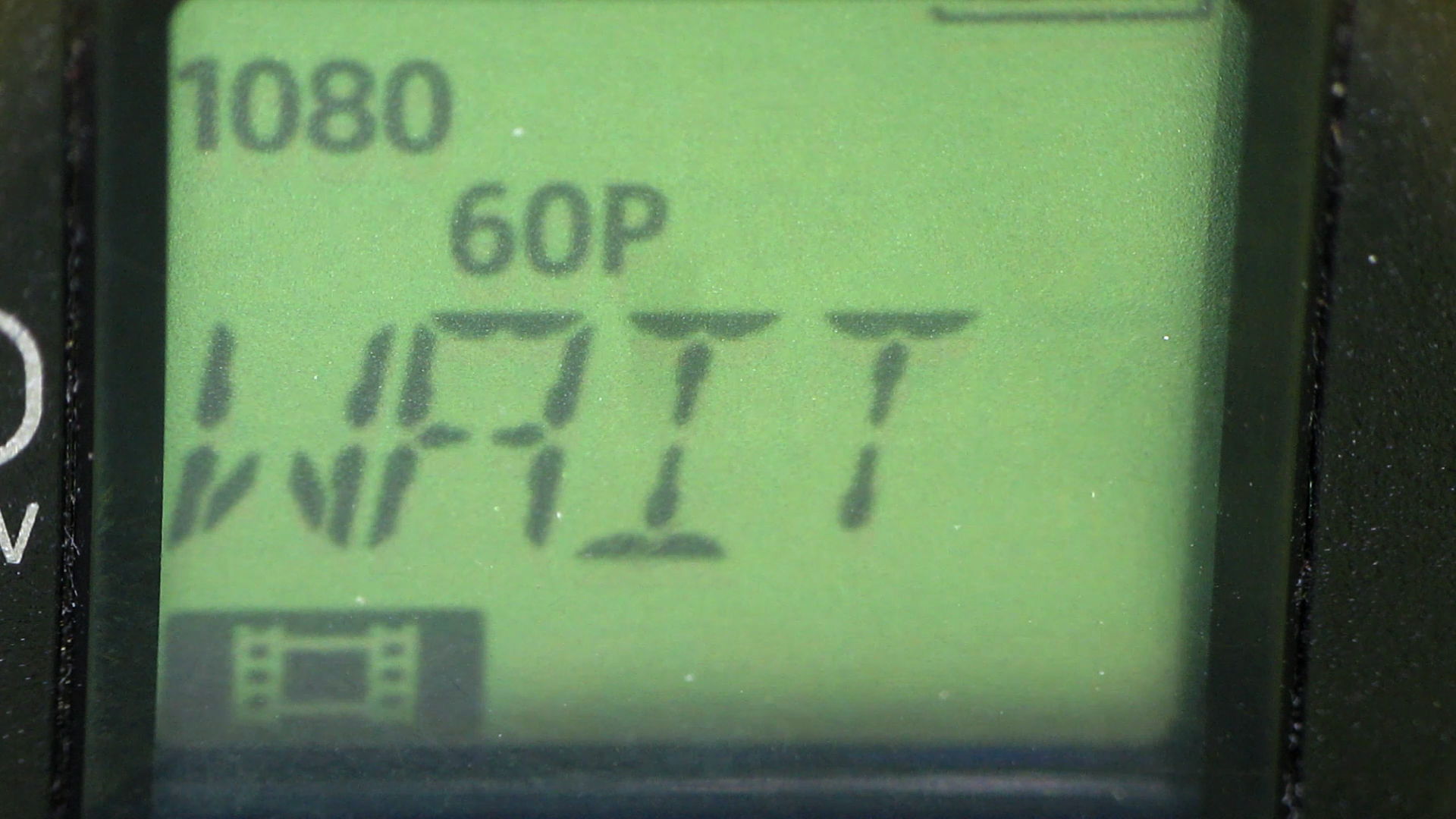
It’s taking stock of the situation:
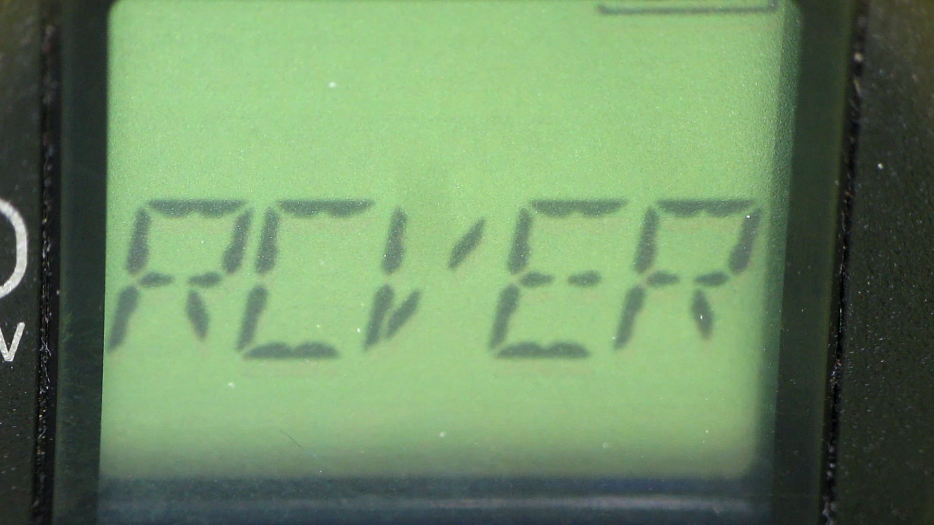
Presumably, it’s patching up the abruptly terminated file:
Another box is on its way to Sony Media Services…
Over the last year, the price of an almost certainly genuine Sony SR-64UY Class 10 UHS-1 MicroSDXC card has dropped by 2.2 dB: $40 to $24. Now, however, the SR-64UY is the “old model”, so you can pay $30 (-1.3 dB) for an SR-64UY2 rated at 70 MB/s transfer speed (up from 40 MB/s), albeit with no change in the card’s speed class.
Huh.
Both cards failed after writing 1 TB of data (give or take maybe 20%) in 4 GB chunks over the course of 100 recording sessions. The cards still work, in the sense that they can store and accurately retrieve data, just not at the Class 4 (not Class 10) speed rating required by the HDR-AS30V at 1920x1080p @ 60 fps.
The table in the Wikipedia Secure Digital article says Class 4 = 4 MB/s, which is slightly faster than the camera produces 4 GB files in 22:43 min:sec = 3 MB/s. A Class 10 card should write at a sustained 10 MB/s, so the SR-64UY write speed has dropped by at least a factor of 3 from the spec. I’d expect the root problem to be the error correction / block remapping / spare pool handling time has grown as the number of failed blocks eats into the card’s overcapacity, but I have no inside information.
When the replacements slow down, I’ll see how they work as Raspberry Pi memory…